TINY - Oven EDILKAMIN - Free user manual and instructions
Find the device manual for free TINY EDILKAMIN in PDF.


| Product type | Pellet stove |
| Brand | Edilkamin |
| Model | TINY |
| Fuel | Wood pellets (diameter 6 mm) |
| Nominal power | 9 kW |
| Reduced power | 2.8 kW |
| Nominal efficiency | 94.1% |
| Reduced efficiency | 96.2% |
| Hopper capacity | 20 kg |
| Autonomy | 9 to 28 hours |
| Fuel consumption | 0.6 to 2 kg/h |
| Minimum draft | 12 / 5 Pa |
| Flue pipe diameter | 80 mm |
| External air intake diameter | 40 mm |
| Power supply | 230 V ~ 50 Hz |
| Average absorbed power | 100 W |
| Ignition absorbed power | 400 W |
| Weight (with packaging) | 217 kg |
| Heating volume | 235 m³ |
| Control system | LEONARDO® (automatic combustion adjustment) |
| Safety devices | Thermocouple, flow sensor, safety thermostat |
| Recommended maintenance | Daily cleaning of the crucible, weekly of the hearth, yearly by a professional |
| Main functions | Remote control, weekly programmable timer, hot air ducting |
| Supplied accessories | Remote control, glove, spatula, dehumidifying salts, connection sleeves |
Frequently Asked Questions - TINY EDILKAMIN
User questions about TINY EDILKAMIN
0 question about this device. Answer the ones you know or ask your own.
Ask a new question about this device
Download the instructions for your Oven in PDF format for free! Find your manual TINY - EDILKAMIN and take your electronic device back in hand. On this page are published all the documents necessary for the use of your device. TINY by EDILKAMIN.
USER MANUAL TINY EDILKAMIN
natural_image
Exterior view of a modern fire extinguisher cabinet with visible flame display (no text or symbols)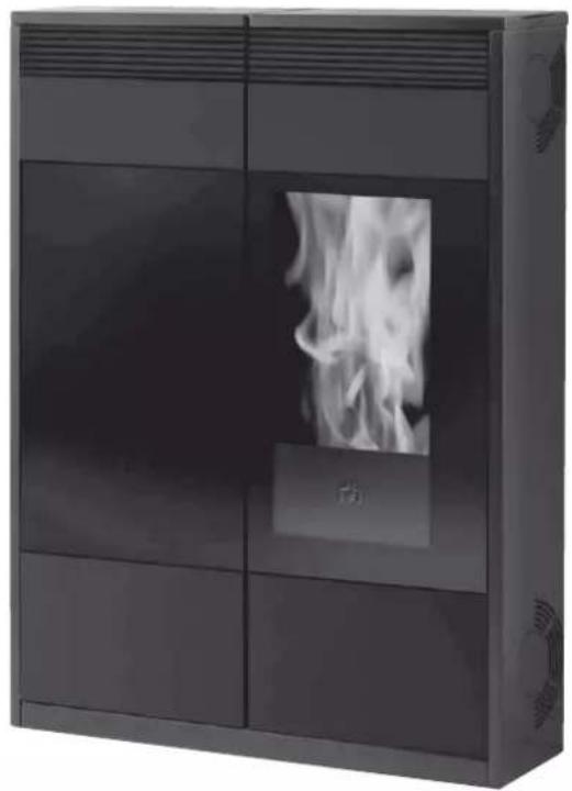
natural_image
Exterior view of a modern black industrial stove unit with visible flame display (no text or symbols)UK Installation, use and maintenance p. 30
F Installation, usage et maintenance p. 58
STUFE A PELLET, a marchio commerciale EDILKAMIN, denominate TINY - KELLY
natural_image
Close-up of a white plastic coiled cable attached to a dark surface, possibly a vehicle or industrial component (no text or symbols visible)CARATTERISTICHE
natural_image
Technical line drawing of a rectangular industrial or storage unit with ventilation grilles and mounting feet (no text or symbols)Fig. 3
Fig. 2
natural_image
Technical line drawings of a mechanical component with two views (top and side), labeled H, showing internal grid structures (no text or symbols beyond labels)Fig. 5
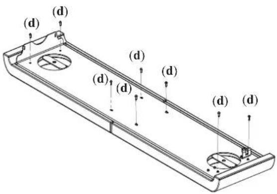
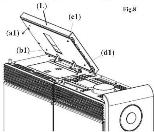
Fig. 6
COLLEGAMENTO USCITA ARIA CALDA DAL TOP
INSTALLAZIONE
USCITA FUMI
COLLEGAMENTO USCITA FUMI DAL TOP
natural_image
Close-up of a mechanical device with labeled component G, no visible text or symbols beyond label (Fig. 6)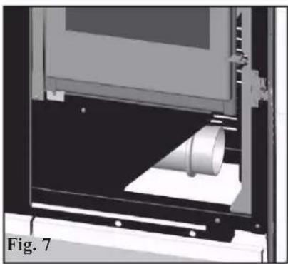
natural_image
3D rendering of a mechanical device with a cylindrical component inserted, labeled 'Fig. 7' (no text or symbols on the diagram itself)PRESA D'ARIA
natural_image
Diagram of a device with two vertical pipes and a labeled 'dal top' at the bottom (no other text or symbols)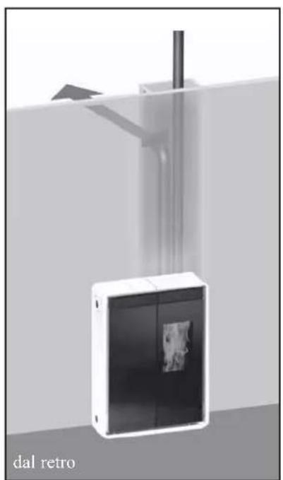
natural_image
Diagram of a device labeled 'dal retro' with a vertical pipe and arrow, no readable text or symbols beyond the label.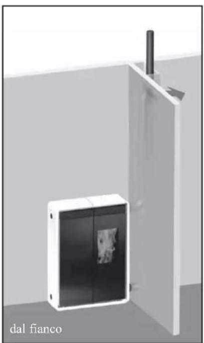
natural_image
3D rendering of a white cabinet with black panels and a vertical pipe inserted into a wall, labeled 'dal fianco' at the bottom (no other text or symbols)ISTRUZIONI D' USO
Prima di accendere.
natural_image
3D diagram of an open device showing internal components and a flower symbol on the cover (no text or labels)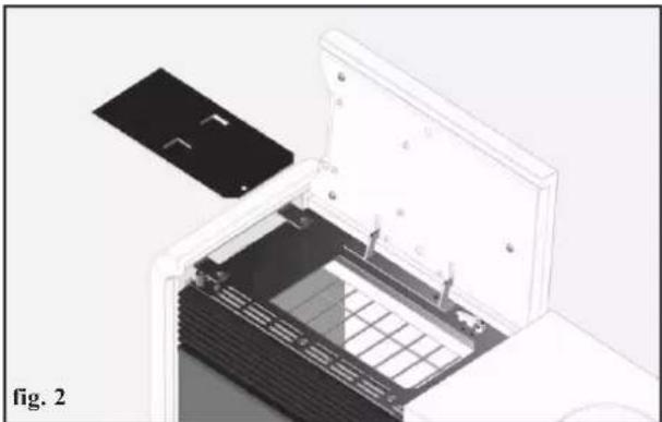
natural_image
Diagram of an open electronic device with a black panel inserted, showing internal components and a grid pattern (no text or symbols)natural_image
Close-up of a gray handheld electronic device with a display showing three buttons (A, M, O) and a 25s mark on the screen.
natural_image
Black handheld electronic device with a digital display and control buttons (no visible text or symbols)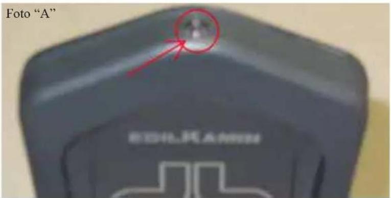
CARATTERISTICHE TECNICHE
natural_image
Exterior view of a desktop computer tower with ventilation grilles and ventilation ducts (no visible text or labels)natural_image
Interior view of a cabinet or storage unit with a labeled component '1' on the door (no text or symbols beyond the label)fig. A
natural_image
Interior view of a double door with open door and shelf, showing no visible text or symbolsfig. B
natural_image
Interior view of a double door with open door, showing internal compartments and a numbered label '3' (no text or symbols on the main structure)fig. C
natural_image
Exterior view of a modern building corner with structural beams and a triangular support (no signage or text)fig. D
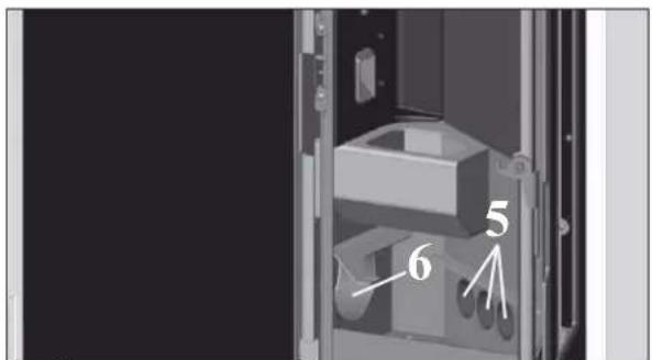
fig. E
MANUTENZIONE
natural_image
Bottle of spray cleaning with a spray can (no visible text or symbols)GlassKamin (cod. 155240)
natural_image
Black and white photo of a vacuum cleaner with attached tubing (no visible text or symbols)Bidone aspiracenere
Congratulations and thank you for choosing our product.
Please read this document carefully before you use this product in order to obtain the best performance in complete safety.
For further details or assistance, please contact the DEALER where you purchased the product or visit the TECHINICAL ASSISTANCE CENTRES page on our website www.edilkamin.com.
NOTE
- After you remove the packaging, please inspect the unit for any damage or missing parts (cladding, remote control only Tiny, connecting sleeves, warranty booklet, glove, technical data sheet, spatula, desiccant).
In case of anomalies please contact the dealer where you purchased the product immediately.
You will need to present a copy of the warranty booklet and valid proof of purchase.
- Commissioning/ testing
Commissioning and testing must be performed by an authorized Edilkamin Technical Assistance Centre. Failure to do so will void the warranty. Commissioning, as specified in standard UNI 10683 consists in a series inspections to be performed with the insert installed in order to ascertain the correct operation of the system and its compliance to applicable regulations.
To locate the Technical Assistance Centre closest to you, please ask your local dealer, call our toll-free number, or visit our website www.edilkamin.com.
- Incorrect installation, incorrect maintenance, or improper use of the product, shall relieve the manufacturer from any damage resulting from the use of this product.
- the proof of purchase tag, necessary for identifying the insert, is located:
-on the top of the package
- in the warranty booklet found inside the firebox
- on the ID plate affixed to the back side of the unit;
This documentation must be saved for identification together with the valid proof of purchase receipt. The data contained therein must be reported when requesting information and made available should servicing be required;
- All images are for illustration purposes only; actual products may vary.
The undersigned EDILKAMIN S.p.a. with head office headquarters at Via Vincenzo Monti 47 - 20123 Milan - Italy - VAT IT00192220192
Declares under its own responsibility as follows:
The pellet stove illustrated below conforms to Regulation EU 305/2011 (CPR) and to the harmonised European Standard EN 14785:2006
WOOD PELLET STOVES, trademark EDILKAMIN, called TINY - KELLY
Year of manufacture: Ref. Data nameplate Declaration of performance (DoP - EK 053): Ref. data tag plate
the wood pellet stove TINY - KELLY is in compliance with the requirements of the European directives:
2006/95/EEC - Low voltage directive
2004/108/EEC - Electromagnetic compatibility directive
EDILKAMIN S.p.a. will decline all responsibility of malfunctioning or damage to the equipment in case of unauthorized substitution, assembly or modifications of any sort on the said equipment on the part of non-EDILKAMIN personnel.
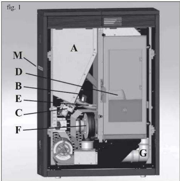
TINY - KELLY stoves heat the air using wood pellets as fuel, with electronically controlled combustion. Hereunder is the explanation of its functions (the letters refer to figure 1).
The fuel (pellets) is provided by the storage hopper (A) and, to the combustion chamber (D) by means of a feed screw (B), which is driven by a gear motor (C).
The pellets are ignited by the air that is heated by an electrical resistance (E) and drawn into the combustion chamber by a smoke extractor (F).
The fumes produced during the combustion process are extracted from the hearth by the same centrifugal fan (F), and expelled through the outlet (G) located on the lower part of the stove.
The stoves are designed to allow warm air to be channelled, to heat an adjacent room.
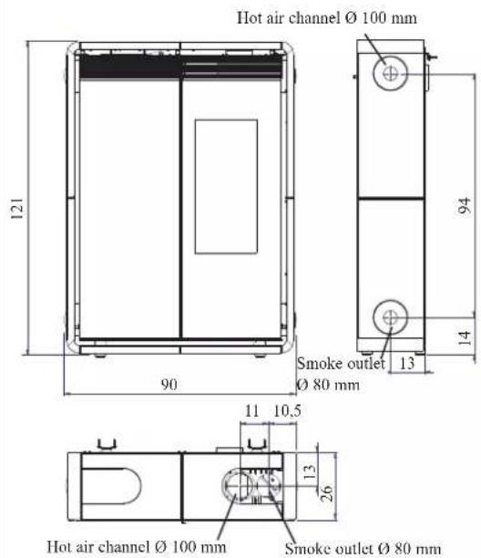
Three outlets are set up to channel warm air (on the rear, side and top). Use the most suitable one (hence the caps will have to be used to close off the other outlets) connecting it with the specifically-designed optional KIT 8.
The hearth is lined with cast iron, closed in the front by two overlapping doors.
- a ceramic glass external door (use the special thermal glove to open the stove).
- an inner door made from ceramic glass which is in direct contact with the fire. The amount of fuel, smoke extraction, and air - fuel supply are all controlled by the software-equipped circuit board, with the aim of obtaining highly efficient fuel consumption and low emissions.
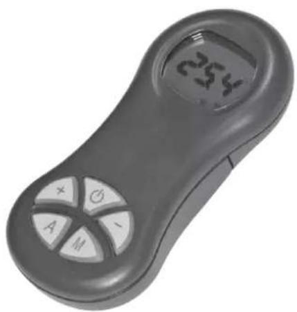
All phases of operation can be managed via radio remote control (provided with the Tiny model).
Whereas the Kelly model has a synoptic panel (M) installed on the lefthand side, which allows you to control and view all phases of operation.
An optional remote control to manage the main functions is available for the Kelly model.
The stove is equipped with a serial port to connect an optional cable (TINY cod. 621240 - KELLY cod. 620550) to be connected to devices that allow remote ignition (e.g. remote telephone, local thermostat).
SAFETY INFORMATION
The TINY - KELLY stoves are designed to provide heating, by automatically burning pellets in the hearth, in the room where they are installed, as well as radiate heat and circulate air coming out of the front grille, and in the adjacent room by circulating channelled air from the rear, right side or top outlet.
- The only risks that may derive from using the stove pertain to non-compliance with installation instructions, direct contact with live electrical parts (internal), contact with the fire or hot parts (glass, pipes, hot air output), or foreign substances being put in the stove.
- Only use wood pellets with 6 mm diameter as fuel.
- Should components fail, the stoves are equipped with safety devices that guarantee automatic shutdown. These are activated without any intervention required.
- In order to function correctly, the stove must be installed in accordance with the instructions given herein and the door must not be opened during operation: combustion is fully automatic and requires no intervention.
- Under no circumstances should any foreign substances be entered into the hearth or hopper.
- Do not use flammable products to clean the smoke channel (the flue section connecting the stove smoke outlet to the chimney flue).
- Hearth and hopper components must only be cleaned with a vacuum cleaner.
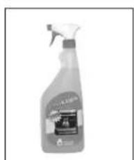
- The glass can be cleaned when COLD with a suitable product (e.g. GlassKamin Edilkamin) and a cloth.
- Do not clean when hot.
- Ensure that the stoves are installed and ignited by a qualified Edilkamin DEALER, in accordance with the instructions given herein.
- When the stove is in operation, the exhaust pipes and door become very hot (do not touch without wearing the thermal glove).
- Do not place anything, which is not heat resistant near the stove.
- NEVER use liquid fuel to ignite the stove or rekindle the embers.
- Do not obstruct the ventilation apertures in the room where the stove is installed, nor the air inlets of the stove itself.
- Do not wet the stove and do not go near electrical parts with wet hands.
- Do not use reducers on the smoke exhaust pipes.
- The stove must be installed in a room that is suitable for fire prevention and equipped with all that is required (power and air supply and outlets) for the stove to function correctly and safely.
- Should ignition fail, DO NOT re-ignite until you have emptied the combustion chamber.
•ATTENTION: THE PELLET EMPTIED FROM THE COMBUSTION CHAMBER MUST NOT BE DEPOSITED INSIDE THE HOPPER.
DIMENSIONS AND FINISHINGS
TINY
- opaque white ceramic cladding
- red ceramic cladding
- black ceramic cladding
KELLY
- burgundy-painted steel cladding
- pearl grey-painted steel cladding
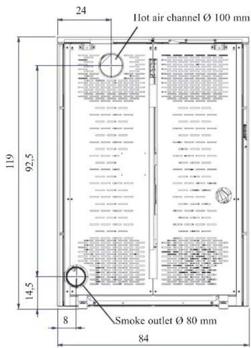
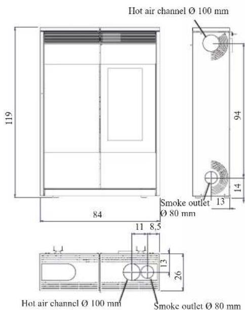
FEATURES
The TINY pellet stove is equipped with SISTEMA LEONARDO ^® .
LEONARDO ^® is a combustion safety and control system which allows optimal performance in all conditions.

This is a safety system that allows optimum operation in all conditions.
LEONARDO® ensures excellent operation thanks to two sensors measuring the pressure level in the combustion chamber and smoke temperature. The detection of and subsequent optimisation of these two parameters is continuous in order to correct operation anomalies in real time.
The LEONARDO® system offers constant combustion, automatically regulating the draft based on the characteristics of the chimney fluc (bends, length, shape, diameter, etc.) and environmental conditions (wind, humidity, atmospheric pressure, installations at high altitude, etc.). The standards for installation must be respected.
LEONARDO ^® system is also able to recognise the type of pellets and automatically adjust the flow moment by moment to ensure the required level of combustion.
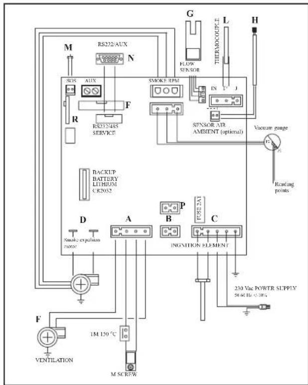
ELECTRONIC CIRCUIT BOARD TINY
wiring diagram
flowchart
graph TD
    M["RS232/AUX"] --> N["AUX"]
    N --> R["R"]
    R --> SOS["SOS"]
    SOS --> AUX["AUX"]
    AUX --> F["F"]
    F --> RS232485["RS232/485 SERVICE"]
    RS232485 --> D["D"]
    D --> A["A"]
    A --> B["B"]
    B --> C["C"]
    C --> F
    F --> M["SMOKE RPM"]
    M --> G["FLOW SENSOR"]
    G --> L["THERAOCOUPLE"]
    L --> H["H"]
    H --> V["Vacuum gauge"]
    V --> Reading["Reading points"]
    V --> Vacuum["Vacuum gauge"]
    V --> In["IN"]
    V --> FJ["J"]
    FJ --> Sensor["SENSOR AIR AMBIENT (optional)"]
    Sensor --> D
    D --> Smoke_expalian["motor"]
    Smoke_expalian --> D
    D --> INGNIITION["INGNITION ELEMENT"]
    INGNIITION --> C
    C --> 230Vac["230 Vac POWER SLPPIV 50.60 Hz-0.10V"]
    V --> 230Vac
    V --> 230Vac
    V --> 230Vac
    V --> 230Vac
    V --> 230Vac
    V --> 230Vac
    V --> 230Vac
    V --> 230Vac
    V --> 230Vac
    V --> 230Vac
    V --> 230Vac
    V --> 230Vac
</details>
ELECTRONIC CIRCUIT BOARD KELLY
wiring diagram

<details>
<summary>flowchart</summary>
```mermaid
graph TD
A["FLOW SENSOR"] --> B["SMOKE THERMOCOUPLE"]
B --> C["R5232"]
C --> D["SMOKE RPM"]
D --> E["INT-I"]
E --> F["SENSOR AIR AMBIENT"]
F --> G["FO CONSOLLE"]
G --> H["BACKUP BATTERY LITHIUM CR2012"]
H --> I["CONSOILIT"]
I --> J["FDSF-2.4T"]
J --> K["230 Vac power supply 50 Hz ~+10%"]
K --> L["IGNITION ELEMENT"]
L --> M["INGNITION Element"]
M --> N["TM"]
N --> O["SMOKE THERMOCOUPLE"]
O --> P["SMOKE RPM"]
P --> Q["R5232"]
Q --> R["SMOKE RPM"]
R --> S["INT-I"]
S --> T["Flow Sensor"]
SERIAL PORT
The Dealer can install an optional on the AUX outlet for controlling the process of switching on and off (e.g. telephone remote, local thermostat), located at the rear oh the stove.
Can be connected via special optional trestle (TINY code 621240 - KELLY code 620550).
The serial port is located inside the stove on the lefthand side.
BACKUP BATTERY
A backup battery is found on the control board (3-Volt CR 2032 battery).
Its failure (not considered a product defect, but normal wear and tear) is indicated with the words "Battery check" for the TINY model and "Batt. 1 - Batt. 2" for the KELLY model.
For more detailed information, please contact the DEALER who has performed the first 1st ignition.
ROOM TEMPERATURE SENSOR
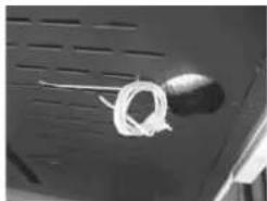
An outlet for the 1 metre-long room temperature cable is provided on the back of the stove.
The sensor, which will be attached to the wall using the bracket provided, is wired onto the end of the cable.
natural_image
Close-up of a white rope tied with a string against a dark surface (no text or symbols visible)FEATURES
| THERMOTECHNICAL CHARACTERISTICS | ||
| Nominal power | 9 | kW |
| Efficiency nominal power | 94,1 | % |
| Emissions CO (13% O_2 ) nominal power | 149 | ppm |
| Smoke mass nominal power | 5,8 | g/s |
| Reduced power | 2,8 | kW |
| Efficiency reduced power | 96,2 | % |
| Emissions CO (13% O_2 ) reduced power | 206 | ppm |
| Smoke mass reduced power | 2,1 | g/s |
| Maximum overheated smoke | 111 | °C |
| Minimum draught | 12 / 5 | Pa |
| Autonomy (min/max) | 9 / 28 | hours |
| Fuel consumption (min/max) | 0,6/2 | kg/h |
| Hopper capacity | 20 | kg |
| Heatable volume * | 235 | m^3 |
| Weight including packaging (Tiny/Kelly) | 217/189 | kg |
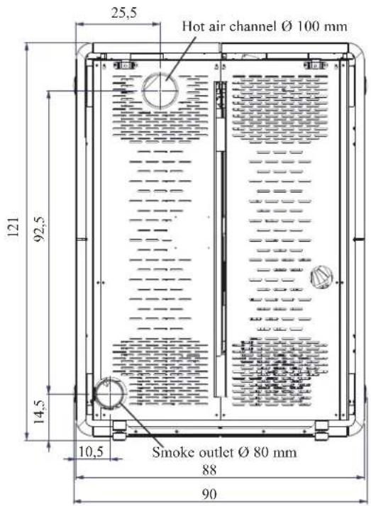
| Smoke outlet pipe diameter (male) | 80 | mm |
| Air intake pipe diameter (male) | 40 | mm |
* The heatable room dimensions are calculated on the basis of pellets with an lhv of at least 4300 kcal/kg and home insulation in compliance with Italian law 10/91, and subsequent changes together with an expected heat output of 33 Kcal/m³ per hour.
* It is also important to consider the position of the stove in the room to be heated.
The data shown above is purely indicative.
EDILKAMIN s.p.a. reserves the right to make changes to these products to improve their performance with no prior warning.
ELECTRICAL CHARACTERISTICS
| Power supply 230Vac +/- 10% 50 Hz | ||
| Average power consumption 100 W | ||
| Power consumption during ignition 400 W | ||
| Remote control frequency (optional) Infrared | ||
| Remote control frequency (as standard) Radio waves 2.4 GHz | ||
| Protection on electronic circuit board 2AT, 250 Vac, 5x20 Fuse | ||
SAFETY DEVICES
| THERMOCOUPLE:placed at the smoke outlet to detect the temperature.Turns the stove on and off and controls its operation based on defined parameters. |
| AIR FLOW SENSOR:placed in the air inlet channel.This intervenes if an anomaly is detected in the combustion air flow and causes insufficient circulation in the smoke ducts. |
| SAFETY THERMOSTAT:trips when the temperature inside the stove is too high. It stops pellet loading, causing the stove to go out. |
COVERING ASSEMBLY
TINY (the KELLY model comes pre-assembled)
natural_image
Technical line drawing of a rectangular industrial or laboratory device with ventilation grilles and mounting feet (no text or symbols)Fig. 3
Fig. 2
natural_image
Technical line drawings of a mechanical component with two views (top and side), labeled H, showing internal grid patterns (no text or symbols beyond labels)Fig. 5
no. 4 Threaded rod M8
no. 4 Ceramic cap fixing stud
no. 28 M4 x 8 Screws
no. 4 Adjustment pin
no. 2 Brackets for attachment to wall with pins and screws
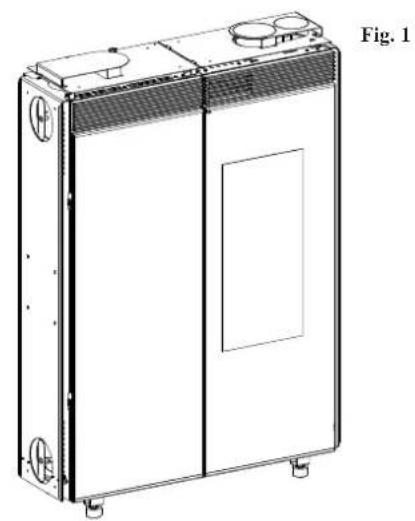
Fig. 1
This figure represents the stove after it has been unpacked.
Note:
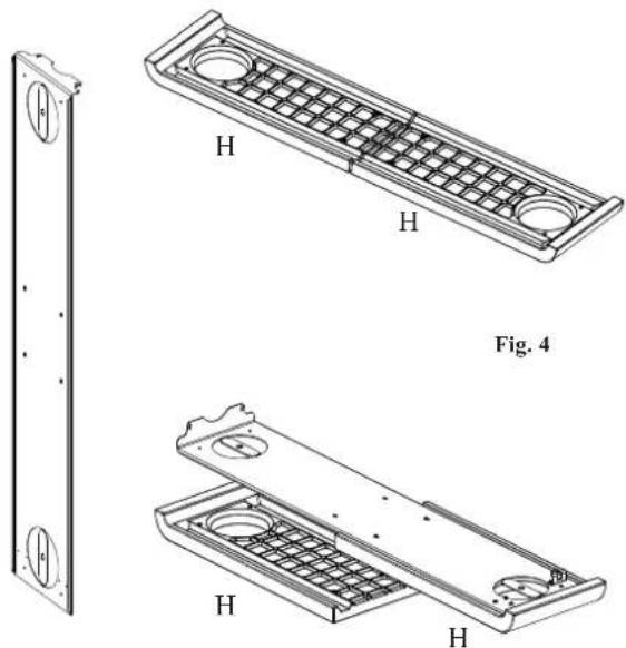
The stove is delivered with the metal part of the side plate coverings already assembled (fig. 2).
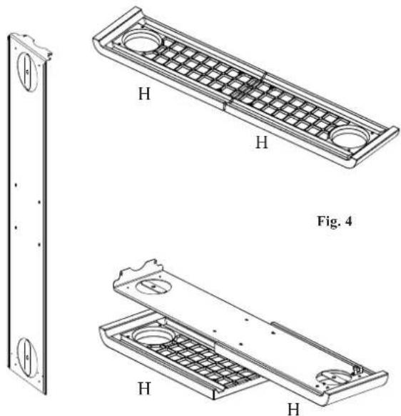
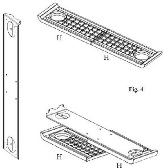
The two panels of the ceramic covering (H- fig. 6) must be assembled as follows:
SIDE COVERING ASSEMBLY: CERAMIC COMPONENTS
Fig. 3/4
Place a pair of the ceramic components (H -fig. 3) on large enough surface and place a cloth or similar item under them to prevent scratching.
Place the metal side (fig. 4) on top after having removed it from the body of the stove.
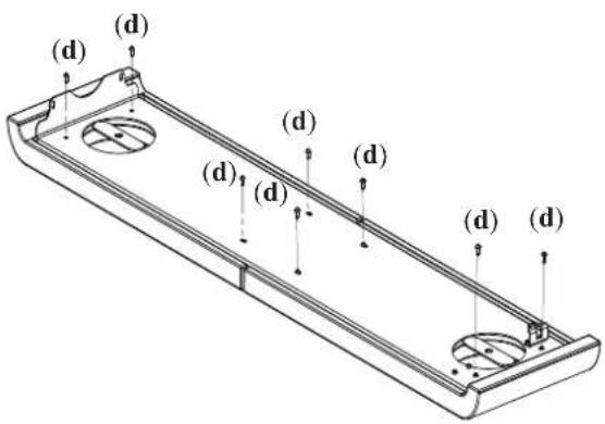
Fig. 5
Screw the 8 M4 x 8 (d) screws provided into the relative bushings on the ceramic components and verify their correct alignment.
ATTENTION!!! Do not screw using force; work in an extremely delicate manner otherwise the threaded inserts may come out of the ceramic side.
Repeat the same step for the second pair of ceramic components H.
COVERING ASSEMBLY
TINY
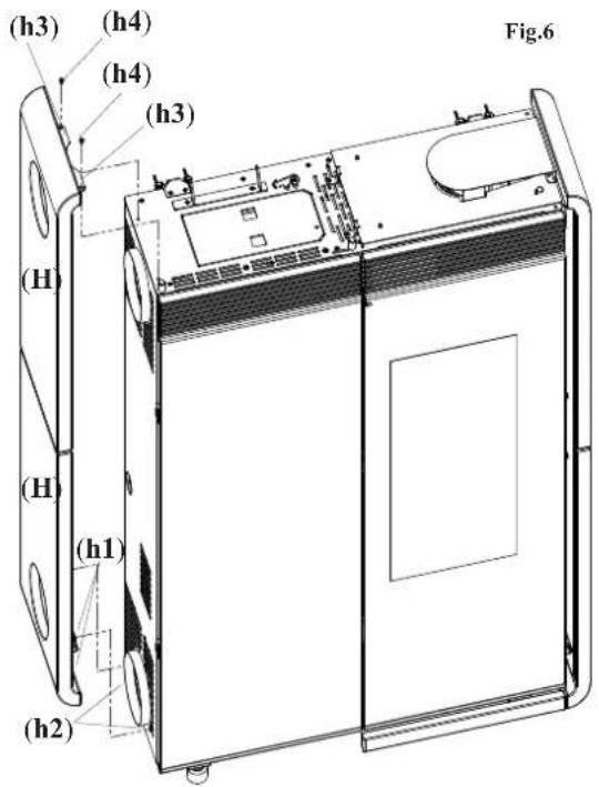
Fig. 7
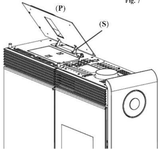
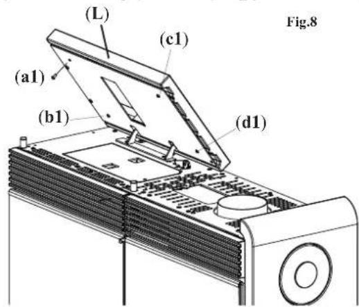
Fig. 6
Attach the sheet metal sides (H) (complete with the ceramic components) using the self-tapping screws removed earlier, proceeding as follows:
- fit the metallic brackets (h1) (present at the base of the internal side) in the pins (h2) that stick out from the stove's structure;
- make the side adhere to the structure in such a way that the brackets (h3) adhere to the top;
- secure the side to the top using the screws (h4) through the holes of the brackets (h3).
LEFT TOP ASSEMBLY
Fig. 7
The left top consists of a painted metal support (P) and a ceramic component (L-fig.8).
The support (P) is supplied already assembled to the stove bracket (S).
Fig. 8
Then assemble the ceramic lid cover (L) using the M6 X 8 screws (a1, b1, c1,d1).
ATTENTION!!! Make sure that the ceramic lid (L) does not rub up against the top during turning and that, when opened to load pellets that it does not close by itself, falling.
TINY
RIGHT TOP ASSEMBLY
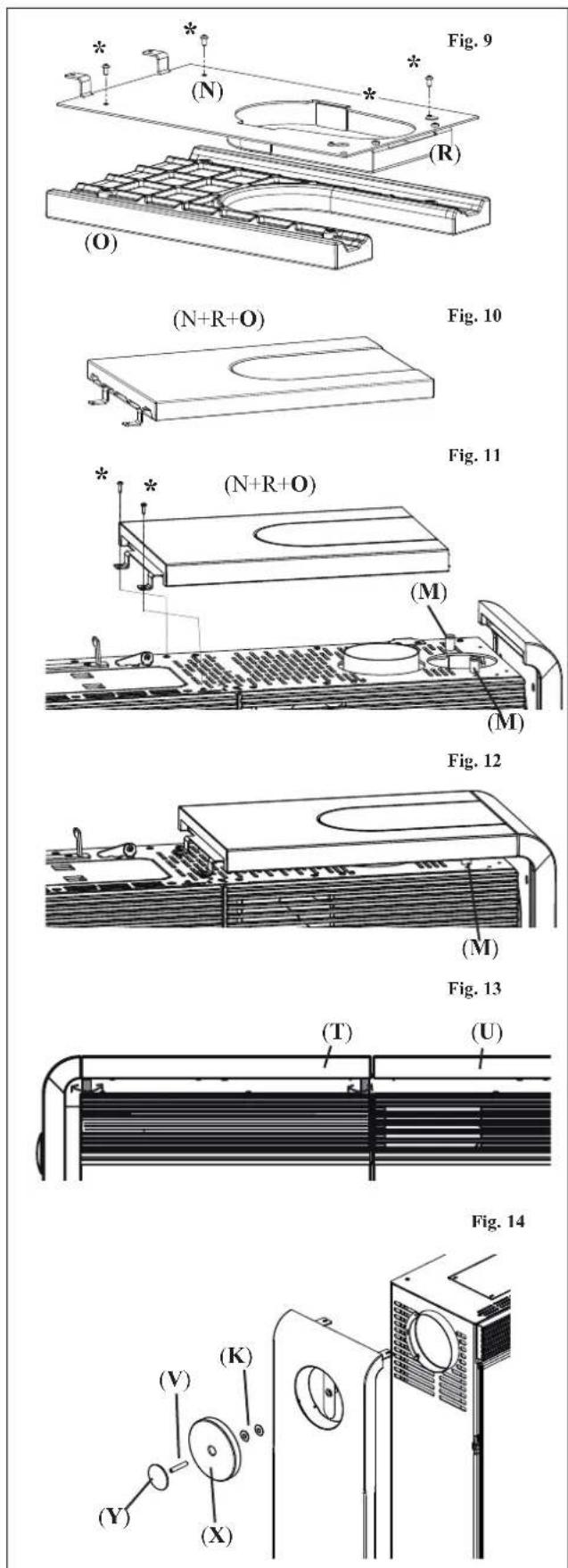
Fig. 9
The right top is composed of painted metal support (N), and a painted closed lid (R) which are already assembled together and also assembled to the stove, and to a ceramic component (O).
(if the smoke outlet or the hot air duct are used with a top outlet, the closed lid (R) should be replaced with the open lid included in the accessories bag).
ATTENTION!!! Place the ceramic component (O) on large enough surface and place a cloth or similar item under it to prevent scratching.
Remove the metal support (N) complete with lid (R) from the stove and secure it with the 4 M4 x8 screws (*) to the ceramic component (O).
Fig. 10
Turn over the ceramic and support assembly (components N, R, O) as shown in the figure.
Fig. 11
Secure the three components (N, R, O) to the stove (in the same starting position) using the two self-tapping screws (*) removed earlier.
Fig. 12/13
Use the 4 pins (M) under the LT and RT tops to align the two ceramic components, right semi-top (U) and left semi-top (T).
Fig. 14
Screw the metallic boss (Y) to the threaded bracket (V). Insert all of it in the ceramic cover (X); Place everything into the ceramic lid (X); complete by inserting two spacers (K) ∅ 40 with hole ∅ 8.
Screw the unit to the side of the stove.
COVERING ASSEMBLY
TINY
LOWER INSERT ASSEMBLY
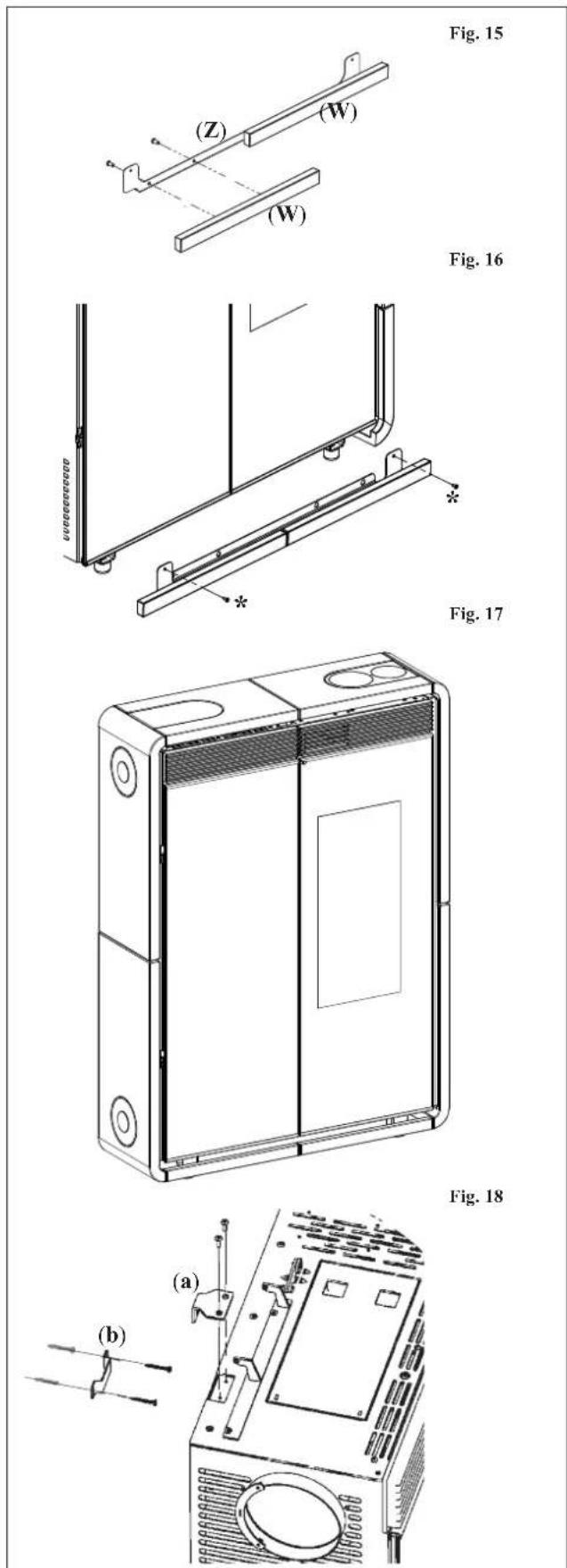
Fig. 15
Fasten the two ceramic inserts (W) to the sheet metal support plate (Z) using the M4x8 screws.
Fig. 16
Fix the sheet metal support complete with the ceramic inserts on the base of the stove using the self-tapping screws supplied; the holes are accessible by opening the two glass doors.
Fig. 17
The figure shows the completely assembled stove.
POSITIONING
Fig. 18
Secure the stove to the wall using the supplied brackets (A and B) or, if necessary, an alternative system that will ensure the stove's stability.
For proper operation, the stove must be level.
Check the load bearing capacity of the floor.
INSTALLATION
Refer to local regulations in the country of use for anything that is not specifically covered in this manual. In Italy, refer to standard UNI 10683 in addition to any Regional or Local Health Authority regulations. If the stove is to be installed in a block of apartments, consult the block administration before installing.
VERIFY COMPATIBILITY WITH OTHER DEVICES
The stove must NOT be installed in the same room as extractors, type B heating appliances and other appliances that may affect its operation. See regulation UNI 10683.
VERIFY THE POWER SUPPLY CONNECTION (the plug must be accessible)
The stove is supplied with a power cable that is to be connected to a 230V 50 Hz socket, preferably fitted with a magnetothermic switch. In the event that the power outlet is not easily accessible, provide a device to cut off the power supply (a switch) upstream of the stove (must be provided by the customer). Voltage variations exceeding 10% can damage the stove (unless already installed, an appropriate differential switch must be fitted). The electrical system must comply with the law; particularly verify the efficiency of the earthing system. The power line must have a suitable cross-section for the stove's power. An inadequate earthing system can cause anomalies for which Edilkamin cannot be held liable.
FIRE PREVENTION SAFETY DISTANCES
The stove can be attached directly to brick and/or plasterboard walls. In the case of combustible walls (wood, for example), you must install adequate insulation in a non combustible material. You are required to adequately insulate the smoke exhaust pipe and the warm air channelling pipe, as they reach high temperatures. All elements made from combustible and/or heat-sensitive material located adjacent to the stove must be arranged at a distance of no less than 20 cm or otherwise be adequately insulated with non combustible insulating material, and in any case materials can not be placed at less than 80 cm in front of the stove as they are directly exposed to the heat radiating from the hearth. Leave a suitable amount of space between the element directly adjacent and the stove in order to comfortably use the synoptic panel located on the left side of the Kelly stove.
AIR INTAKE
There must be an air inlet behind the stove with a minimum diameter of 80 cm^2 . This must be connected to the outside in order to guarantee sufficient air supply to the stove for combustion.
SMOKE OUTLET
The stove must have its own smoke outlet (the smoke cannot be discharged into a smoke flue used by other devices).
The smoke exhaust is expelled through the 8 cm-diameter outlet located on the back, right side or top. The smoke outlet must be connected to outside by means of suitable steel pipes and must be free from obstructions. The stove smoke discharge must be connected with outside by means of steel or black pipes EN 1856 certified. The pipe line must be hermetically sealed. The pipes must be sealed and insulated using materials that are resistant to high temperatures(high temperature silicone or mastic). The only horizontal section allowed may be up to 2 m long. It is possible to use up to two curves with a maximum angle of 90° (with respect to the vertical axis). If the outlet is not fitted into a chimney flue, a vertical section and a wind guard are required (reference UNI 10683). The vertical duct can be internal or external. If the smoke channel is outside, it must be appropriately insulated. If the smoke channel is fitted inside a chimney flue, the latter must be suitable for solid fuel. If it is wider than 150 mm in diameter it must be improved by entering a pipe that has a suitable cross-section and is made of suitable material (e.g. 80 mm diameter steel). All sections of the smoke duct must be accessible for inspection. The chimney pots and smoke ducts connected to the solid fuel appliances must be cleaned once a year (verify whether a specific legislation exists in your country). Failure to regularly inspect and clean the stove increases the probability of a fire occurring in the chimney pot. In that case, proceed as follows: Do not use water to extinguish the fire; Empty the pellet hopper; Contact specialist personnel before reigniting the stove.
TYPICAL EXAMPLES
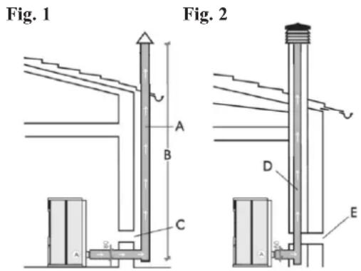
A: insulated steel flue
B: minimum height of 1.5 m and in any case above the height of the roof gutter
C-E: air intake from inside room (minimum internal section: 80 cm²)
D: steel flue, inside existing brick-built chimney.
CHIMNEY POT
The main characteristics are:
- an internal cross-section at the base, which is the same as that of the chimney flue
- an outlet cross-section which is no smaller than twice that of the chimney flue
- its position must be high enough to catch the wind and avoid downdraft areas in turbulent wind, it must be high enough to catch the wind and avoid downdraft areas in turbulent wind.
INSTALLATION
HOT AIR CIRCULATION
The supply of warm air in the room where the stove is installed is provided by a grille installed on the top right of the stove front.
Tiny and Kelly are also supplied with a channelling system that allows warm air to be channelled to heat adjacent rooms.
It is possible to set the stove up so that the air channelling pipe comes out from the top, the back or the right side (the B - H connecting sleeves are provided separately in the package).
CONNECTING THE WARM AIR OUTLET ON THE TOP
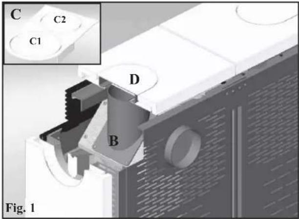
In order to connect the outlet you must use the pre-cut lid provided separately (C) by removing the diaphragm C1, instead of the uncut lid (D - fig.1).
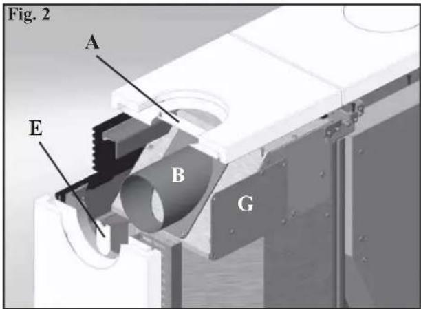
Remove the pre-cut diaphragm (A - fig. 2) from the metal plate of the right ceramic support and attach the connecting sleeve (B - fig. 1).
Slide and fit the channelling pipe onto the sleeve (B) through the hole obtained on the lid C.
CONNECTING THE WARM AIR OUTLET ON THE RIGHT SIDE
To connect the channelling pipe all you need to do is remove the pre-cut diaphragm (E - fig. 2) from the metal plate of the right ceramic support and attach the connecting sleeve (B - fig. 2). Fit the tube over the connecting sleeve (B) by sliding it through the hole in the ceramic (in this case, the ceramic cap is not used).
CONNECTING THE WARM AIR OUTLET ON THE BACK
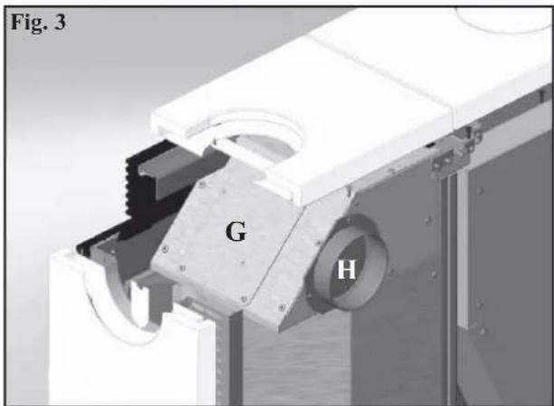
It is also possible to set the stove up with the channelling pipe outlet on the back (fig. 3). In this case you must remove the lid from the rear outlet (G-fig.2) and attach it in position G - fig. 3.
Install the required connecting sleeve (H-fig.3) and fit it onto the channelling pipe.
WARM AIR DISTRIBUTION CONTROL
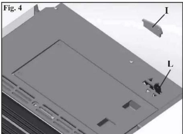
The distribution of warm air can be adjusted manually using lever L which is accessible by lifting the top left ceramic lid (steel for Kelly) (fig. 4).
N.B. inorder to operate the control lever you must remove the security plate (I-fig.4).
It is possible to channel all of the warm air into the room where the stove is installed (lever fully to the right), all of the air into the adjacent room (lever fully to the left) or partially to both rooms (lever in the central position).
An optional KIT 8 is available in order to channel the warm air (see page 42).
It is essential to remember the importance of proper insulation on the pipe where the hot air passes to avoid dispersion. Avoid curves in the pipe as much as possible.
N.B.: IT IS ADVISABLE TO USE CHANNELLING PIPES OF A MAXIMUM LENGTH OF 3 M WITH 2 CURVES.
INSTALLATION
SMOKE EXHAUST
Tiny and Kelly are designed to have the smoke exhaust pipe connected to the top, the back or the right side. The stove is supplied already set up for a top-connecting smoke exhaust pipe.
CONNECTING THE SMOKE EXHAUST PIPE ON THE TOP
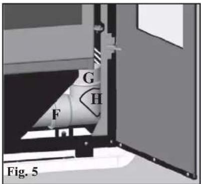
In order to connect the pipe (not supplied) simply fit it onto the elbow joint (G-fig.5) which is already mounted on the stove and accessible by opening the righthand glass door (fig. 5). An inspection lid for cleaning (H) is located on the elbow joint (G). When using the top outlet you must use the pre-cut lid (C - fig. 1 on page 39) by removing the diaphragm C2, in place of the uncut lid (D - fig. 1 on page 39).
CONNECTING THE SMOKE EXHAUST PIPE ON THE BACK
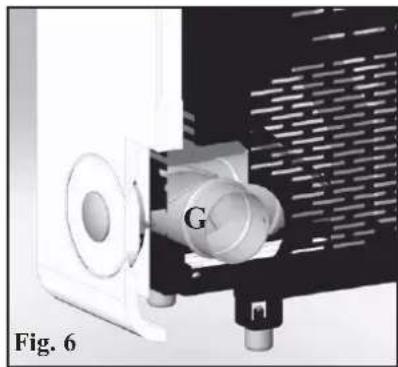
To set up the stove with the smoke exhaust on the back simply loosen the locking clamp (F-fig.5/6) of the elbow joint and rotate it by 90 degrees. By doing so you can connect the pipe to the back by passing it through the hole located at the bottom of the sheet metal back.
CONNECTING THE SMOKE EXHAUST PIPE ON THE SIDE
By removing the elbow (G-fig.6) you can connect the smoke exhaust pipe to the side (fig. 7) through the hole located on the ceramic side. To do this, simply remove the pre-cut diaphragm from the righthand sheet metal side of the side ceramic support to allow the pipe to pass through (in this case, the ceramic cap is not used).
The elbow (G) can be used externally to collect condensation.
natural_image
Close-up of a mechanical device with labeled component G, shown in technical view (no readable text or symbols)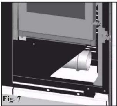
natural_image
3D rendering of a mechanical device with a cylindrical component inserted, labeled 'Fig. 7' (no text or symbols on the diagram itself)AIR INTAKE
There must be an air inlet behind the stove with a minimum diameter of 80 cm ^2 .
This must be connected to the outside in order to guarantee sufficient air supply to the stove for combustion.
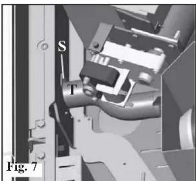
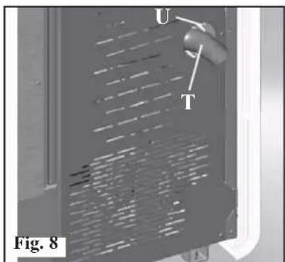
There is a hole (U - fig. 8) on the back of the stove designed to set up an air inlet connected directly to the outside.
By opening the front left-hand side door (fig. 7) it is possible to detach the flexible pipe (T) from its support (S) and push it through the hole (U) on the back of the stove.
This pipe (T) will then have to be connected to the outside.
In this case, there may be condensation problems and it is necessary to protect the air intake with a grille, which must have a free section of at least 12 cm ^2 .
In the case of wall-mounted stoves, an air intake connected with the outside is required.
The pipe must be less than 1 metre long and have no bends.
It must end with a section at 90^ facing downwards or be fitted with a wind guard.
INSTALLATION
KIT 8 (code 297360)
Note: THE FIRST PART OF THE FLEXIBLE PIPE MUST BE COMPLETELY "RELAXED" IN SUCH A WAY TO ELIMINATE CORRUGATION. IN THIS WAY, THE INTERNAL DIAMETER WILL BE SLIGHTLY ENLARGED TO FAVOUR ENTRANCE.
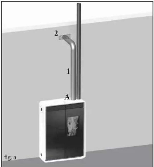
- Define the position of the stove with respect to the walling (fig. a).
- Enable the hot air channelling control lever (see page 39).
- Place the stove in its final position and fasten it to the wall using the supplied brackets (A and B) or, if necessary, an alternative system that will ensure the stove's stability (see page 40).
- Extend the aluminium pipe (2) for hot air channelling, without connecting the stove outlet.
- Fit the aluminium pipe to the hot air outlet (A).
- Install the terminal outlet (3) and its aluminium pipe (2).
It is essential to remember the importance of proper insulation on the pipe where the hot air passes to avoid dispersion. Avoid curves in the pipe as much as possible.
| KIT 8 | n° code | ||
| - | Pipe blocking clamp | 2 461 | 60 |
| 1 | ∅ 10 pipe | 1 162 | 520 |
| 2 | Smoke outletend-piece | 1 293 | 430 |
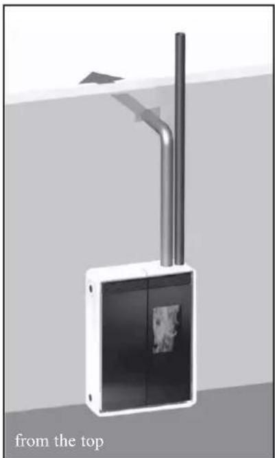
EXAMPLES OF WARM AIR CHANNELLING AND SMOKE EXHAUSTS
natural_image
Diagram of a device with two vertical tubes and a central panel, labeled 'from the top' (no text or symbols on the diagram itself)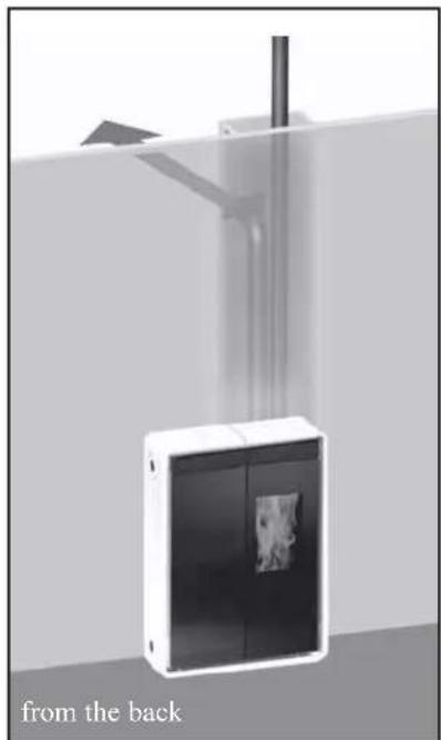
natural_image
Exterior view of a modern office building (no signage)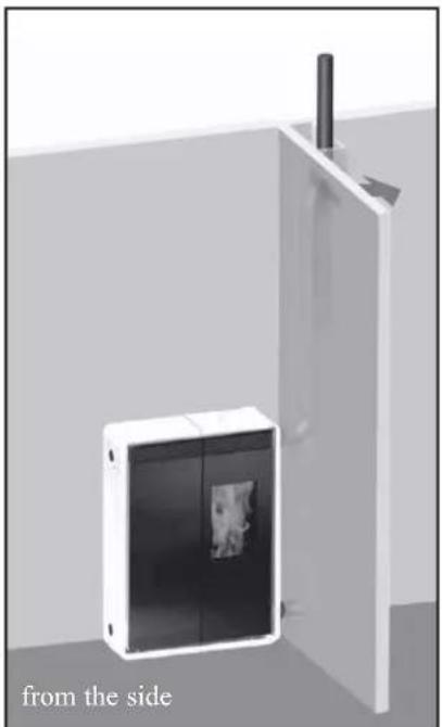
natural_image
Exterior view of a modern office building (no signage)INSTRUCTIONS FOR USE
Before igniting.
You must consult the Edilkamin DEALER in your area when igniting the stove for the first time, in order for the stove to be calibrated according to the type of pellets and installation conditions, thereby validating the warranty.
There may be a slight smell of paint the first few times it is ignited, however, this will disappear quickly.
Before igniting you must check:
=> that installation is correct
=> the power supply
=> that the door closes properly to a perfect seal (inner righthand door).
=> that the combustion chamber is clean
=> that the display is on standby (the date, power or temperature flashes).
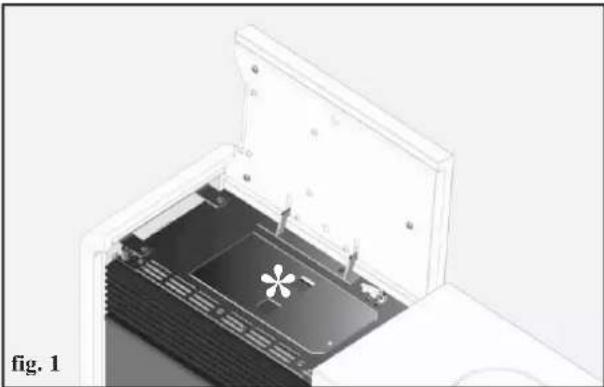
Filling the pellet hopper
To access the hopper open the left ceramic/steel top * (fig. 1-2).
THE CERAMIC TOP IS VERY FRAGILE. HANDLE IT WITH CARE WHEN OPENING AND CLOSING IT.
ATTENTION:
use the glove supplied when filling the stove whilst it is running and therefore is hot.
natural_image
3D diagram of an open device showing internal components and a star-shaped feature, labeled 'fig. 1' (no text or symbols on the diagram itself)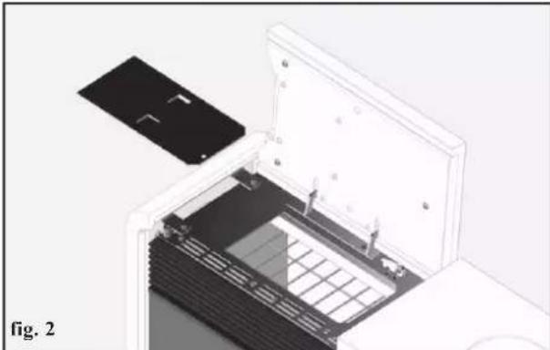
natural_image
Diagram of an open electronic device with internal components, showing a black panel and grid structure (no text or symbols)NOTE regarding the fuel.
TINY - KELLY is designed and programmed to burn wood pellets with 6 mm diameter.
Pellets are a type of fuel in the form of little cylinders, made from
compacted sawdust, compressed under high pressure with no adhesives or foreign materials. They are sold in bags of 15 kg.
For the stove to function properly, you MUST NOT burn anything else in it. Using other materials (including wood) will render the warranty null and void. Such use is detected by laboratory analyses.
Edilkamin has designed, tested and programmed their stoves to guarantee the best performance when pellets with the following characteristics are used:
diameter: 6 millimetres - maximum length: 40 mm - maximum moisture content: 8% - calorific value: at least 4300 kcal/kg.
If pellets with different characteristics are used, the stoves must be recalibrated – a similar procedure to that carried out by the DEALER when the stove is ignited the first time.
Using unsuitable pellets may: decrease efficiency; cause malfunctions; stop the stove from functioning due to clogging, dirt on the glass, unburnt fuel, etc.
A simple, visual analysis of the pellets may be carried out:
Good quality: smooth, uniform length, not very dusty.
Poor quality: with longitudinal and transverse cracks, very dusty, various lengths and mixed with foreign matter.
INSTRUCTIONS FOR USE
TINY MODEL SERIES RADIO REMOTE CONTROL
This controls all the functions.
Key to buttons and display:
: to turn off and on (to go from remote control on stand-by to remote control on)
+/- : to increase/decrease the various regulations
A : to select Automatic function
M : to select Manual function and access the control and programming menus
natural_image
Close-up of a gray handheld electronic device with control buttons and a display screen (no visible text or symbols)
- icon flashing: remote control searching for network
- icon fixed: remote control with connection enabled

flat battery
(press "A" and "M" in parallel for a few seconds to lock or unlock the keypad)

programming enabled
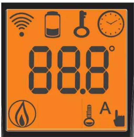
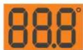
alphanumeric display consisting of 16 figures arranged in two lines of 8 figures

- icon flashing: Stove turning on - icon fixed: Stove working

manual adjustment function (display shows working power)
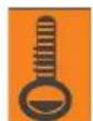
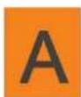
automatic function (display shows temperature)
The display also shows other useful information in addition to the icons described above.
- Stand-by position:
shows room temperature (20°C), kg of pellets (15 kg) remaining in tank and current time (15.33)
- Manual work phase:
shows power set (Power 1), room temperature (20°C), kg of pellets and autonomy remaining (15 kg 21 hrs)
- Automatic work phase:
shows temperature set (Set 22°C), room temperature (20°C), kg of pellets and autonomy remaining (15 kg 21 hrs).
DO NOT PRESS THE BUTTON MORE THAN ONCE

Note: If the radio control is not used for a few seconds, the display will go dark as it has moved into the power saving function. The display can be reactivated by pressing any button.
INSTRUCTIONS FOR USE
CONTINUED: TINY model series radio remote control
Filling the cochlea.
The first time you use the product, or should the tank be completely emptied of pellets, to fill the cochlea press both keys “+” and “-” on the remote control at the same time, holding for a few seconds. As you release the keys, the display should show the wording “LOAD”.
This should be carried out before ignition if the stove has stopped due to having run out of pellets, at the end of operation to empty the combustion pot before turning.
It is quite normal for some pellets to remain, that the cochlea cannot suction.
Automatic igniting.
With the insert on stand-by, press and hold the key, the remote control for 2 seconds. This will start-up the ignition procedure, showing the wording "START". At the same time, a countdown in seconds begins (from 1020 to 0). Ignition is not at a preset time, however: its duration is automatically shortened if the board reports that certain tests have been passed. The flame appears after about 5 minutes.
Manual igniting.
Temperatures of below 3^ C will not allow the electrical resistance to heat sufficiently. In this case, or should the resistance be temporarily out of action, Diavolina ^ type fire-starters can be used.
Insert a piece of lit Diavolina® into the combustion chamber, close the door and press in remote control.
POWER REGULATION
- Remote control manual operation
With the stove working, press the key "M" on the remote control once. The display will show the word "POWER P". (specifying the power at which the insert is working). Press the keys "+" or "-" to increase or decrease the insert's working power (from "POWER P1" to "POWER P5").
- Remote control automatic operation
Press key "A" to switch to automatic operation, adjusting the temperature desired for the room (use the "+" and "-" keys to set the temperature from 5°C to 35°C, and the insert will regulate working power required to reach the temperature set.
If a temperature below that of the room is set, the insert will stay on "POWER P1".
Turning off
With the stove running, press and hold the key in the remote control for 2 seconds. The turn-off procedure will begin, showing a countdown on the display from 9 to 0 (for a total of 10 minutes).
The turn-off phase involves:
- Interruption of pellet supply
• Maximum ventilation. - Smoke expulsion motor.
Never pull the plug out whilst the device is still in the process of turning off.
INSTRUCTIONS FOR USE
CONTINUED: TINY model series radio remote control
OPERATIONS THAT CAN ONLY BE CARRIED OUT BY REMOTE CONTROL
Clock regulation
Press and hold the key "M" for 2 seconds to access the "CLOCK" menu. This allows you to set the internal electronic board clock.
By then pressing the key "M", the following data appears in sequence and can be regulated:
day, month, year, hour, minutes, day of the week.
The wording “SAVE???” will appear for confirmation with "M". This will allow you to check that the operations performed are correct, prior to completion (the wording “SAVE” will then be shown on the display).
Weekly timer
Press and hold the "M" key on the remote control for 2 seconds. This turns on the clock regulation and by pressing the '+' key, the weekly timer function is accessed, with the display showing the description "PROGRAMM ON/OFF".
This function allows you to set a number of times the insert turns on and off per day (up to a maximum of three), each day of the week.
As you confirm the display with the key "M", one of the following options will appear:
NO PROG. (no programme set)
DAILY PROGRAM (single programme for every day of the week)
WEEKLY PROGRAM. (specific programme for each day individually)
Use the “+” and “-” keys to switch between programmes.
Use key "M" to confirm the option "DAILY PROGRAM" to choose the number of programmes (turn on/off) to be carried out per day.
Use the “DAILY PROGRAM” to set identical programme/s for every day of the week.
By then pressing the “+” key, the following can be seen:
- Prog. no.
- 1st prog. (one turn on and one turn off per day), 2nd prog. (identical), 3rd prog. (identical)
Use the “-” key to show in reverse order.
If the 1st programme is selected, the turn on time is shown.
The display shows: 1 "ON" at 10 Use the "+" and "-" key to change the hour. Confirm with the "M" key.
The display shows: 1 "ON" at 30 Use the "+" and "-" key to change the minutes. Confirm with the "M" key.
The same applies for the turn-off time to be set and for subsequent turning on and off.
Confirm by pressing "M" and the wording "SAVE??" will appear on the display.y.
When confirming "WEEKLY PROGRAM", you will need to choose the day to which the programming is to apply:
1 Mon ; 2 Tues; 3 Wed; 4 Thurs; 5 Fri; 6 Sa; 7 Sat
Once you have chosen the day, use the “+” and “-” key and confirm with the "M" key, to programme in the same way as for the “DAILY PROGRAM”, choosing whether or not to enable a programme for each day of the week, and if so choosing number of interventions and at what times.
Should you make an error during programming, you can leave the programme without saving. As you press a key, the display will show the word "NO SAVE".
Changing pellet loading
Press the "M" button for two seconds from the radio control and scroll the display instructions with the "+" and "-" buttons. You will come across the message "User menu" and when you confirm, the message "ADJ-PELLET and ADJ-DRAUGHT" will appear.
If we set "Auto-adjust. ON", the system will automatically adjust pellet dropping. Alternatively, if we set "Auto-adjust.
OFF," we can manually correct pellet dropping, varying the range in terms of percentages (+/- 30 %).
By confirming this function with the menu key, you can access the function to adjust pellet loading. By decreasing the value set, pellet loading is decreased. By increasing the value set, pellet loading increases. This function is useful if changing the pellet type for which the insert has been calibrated and loading therefore needs correcting.
Should this correction not suffice, contact the Edilkamin-authorised Dealer, to establish the new operating axis.
Notes on flame variability
Flame status may vary depending on the type of pellet used, in addition to normal solid fuel flame variability and regular combustion chamber cleaning carried out automatically by the boiler.
(N.B.: which does NOT replace necessary cold suction by the user prior to ignition).
INSTRUCTIONS FOR USE
CONTINUED: TINY model series radio remote control RESERVE WARNING
The stove is fitted with an electronic function that detects the residual quantity of pellets in the tank.
The detection system is integrated into the electronic board, allowing you to see how many hours and kg are left until pellet exhaustion, at all times. For correct system function, it is important that the following procedure is followed during the first ignition (by the Dealer).
1 ^st ignition/test by the Edilkamin authorised Dealer
Start-up must be carried out as prescribed by point 3.21 of standard UNI 10683.
This standard indicates the control operations to be carried out in situ, aimed at ascertaining correct system function.
Pellet reserve system
Before enabling the system, you need to load a sack of pellets into the tank and use the stove until the loaded fuel has run out. This allows for a short system road test.
After this, the tank can be filled completely and the stove started up.
When running, at the time at which a whole 15 kg sack of pellets can be loaded, the display will show the word "RESERVE" flashing.
At this point, after having poured in a sack of pellets, you need to 'inform' the memory that you have loaded 15 kg. To do so, proceed as follows:
- press the "M" key (for approximately 3-4 seconds) until the word "CLOCK" appears.
- press the "+" key until the word "RESERVE" appears.
- press the "M" key until the following screen appears,
Kg remaining in tank
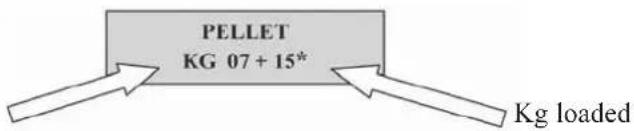
then use the “+” key to take the figure (*) to the value equal to the Kg of pellets loaded (15 kg in the above example).
- press the "M" key to confirm
- press the key to exit.
After having completed the above procedure, after having consumed the 15 kg, the wording "RESERVE" will appear flashing at intervals. After which the operation must be repeated, from point 1 to point 5.
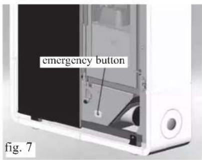
EMERGENCY BUTTON
If the radio remote control fails you can access the basic functions using a red emergency button located under the outer door, to the right (see fig 7).
Press the button once or several times to enable the desired function:
- A STOVE OFF
by pressing the red button for 2 seconds this turns on.
- A STOVE 54 ON
by pressing the red button for 2 seconds this turns off.
- A STOVE 54 ON
manual mode, by pressing the red button, you go from P1 to P5.
- A STOVE 54 ON
automatic mode, by pressing the red button, you go from 5°C to 30°C.
RADIO ANTENNA
The radio signal is received from the radio remote control via a small antenna built into the circuit board.
INSTRUCTIONS FOR USE
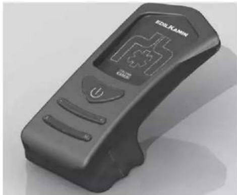
OPTIONAL REMOTE CONTROL code 633280 FOR KELLY MODEL

: ignition / shutdown button
- : button to increase the power/operating temperature (when inside a menu, it increases the displayed variable)
- : button to increase the power/operating temperature (when inside a menu, it decreases the displayed variable)
A : button to toggle from manual and automatic mode
M : button to toggle from automatic to manual mode
An infrared remote control is easily identified through radio transmission as it has its transmission LED at the tip. Refer to photo "A" below.
natural_image
Black handheld electronic device with a display screen and control buttons (no visible text or symbols)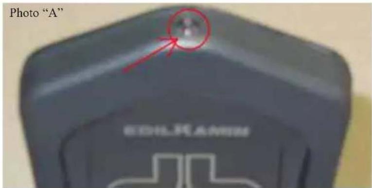
TECHNICAL CHARACTERISTICS
When a button is pressed, the backlight goes on, which indicates that the remote control is transmitting the signal. The "beep" emitted by the stove confirms its reception.
CAPACITY
- the remote control transmits by means of an infrared signal within a range of 4-5 metres. The LED transmission signal must be in line with the receiving LED of the stove for the signal to be transmitted correctly. This must also be in a free-field environment, therefore, free of obstacles, is possible to cover a distance of 4-5 meters.
BATTERY LIFE
the remote control works with 3 alkaline 1.5V AAA batteries. Their duration depends upon usage, however, the average duration is that of an entire season.
- The operating temperature is: 0-40°C
- The correct storage temperature is : -10/+50°C
- Operating humidity is: 20-90% R.H with no condensation
- Degree of protection is: IP 40
- Weight of remote control with batteries: 160gr
INSTRUCTIONS FOR USE
Synoptic panel for the Kelly model
Panel 0/1 button
To turn the stove on or off and quit time programming (prog).
Panel MENU key
This switches the stove from Manual to Automatic mode and vice versa and allows you to programme the timer (prog) and switch from adjusting the power to adjusting the temperature
"+" and "-" panel keys
These allow you to move within the programming mode of the timer (prog) and adjust the set temperature or power.

Remote control receiver
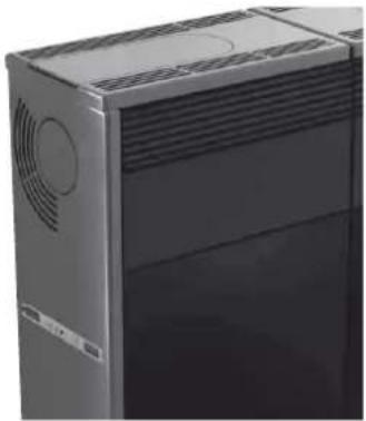
natural_image
Close-up of a desktop computer tower case with ventilation grilles and ventilation ducts (no visible text or labels)Display unit messages
Ac: ignition stage (flame appearance)
Ar: second ignition stage (flame stabilizing) before the operating stage
Of: shutdown stage (10 minutes)
P1 or P2 or P3: power level set
8-29: temperature set for automatic operation
H1..H7: stoppage problem identification number (see p. 55)
Pu: automatic combustion chamber cleaning under way
: motor stopping; wait a few tens of seconds before entering other commands.
When the stove is on standby, this flashes to show the mode it will restart in and when.
SCREW FEEDER LOADING
If the pellet hopper empties completely, press the + and - keys together to fill the screw feeder.
This must be done before igniting the stove again if it has shut down due to running out of pellets.
It is normal for a few pellets to be left in the hopper, which the screw feeder is not able to pick up.
Automatic ignition
Hold the 0/1 key down for two seconds with the stove on standby to start the ignition procedure. Ac appears on the display for a few minutes (the ignition procedure does not actually take a preset time: it is automatically shortened if the electronics detect that certain tests are passed). The flame appears after about five minutes. It is normal for a little smoke to be seen in the combustion chamber before the flame appears. "Ar" appears on the display until the flame stabilizes.
Manual ignition
At temperatures of less than 3^ C (too low for the heating element to glow) or if the heating element is temporarily out of order, a firelighter may be used for ignition. Put a piece of well lit firelighter in the combustion chamber, close the door and press 0/1.
ADJUSTING THE POWER (when the stove is working, press the MENU key to switch between modes)
- Manual mode
adjust the working power (from P1 to P3) and the ventilation.
INSTRUCTIONS FOR USE
CONTINUED: Synoptic panel for the Kelly model
- Automatic mode
Set the temperature which the room is to reach; the stove automatically adjusts the working power to reach it (P3) or maintain it (P1).
If you set a lower temperature than current room temperature, the stove operates at P1 and consumes the corresponding quantity of pellets.
Note on flame variability
Any variations in the state of the flame depend on the type of pellet used, the normal variability associated with solid fuels and the periodic automatic combustion chamber cleaning (which does NOT replace the essential cold vacuum-cleaning by the user before ignition).
Switching off
Hold the 0/1 key down for two seconds while the stove is operating. The shutdown procedure starts and the word "Off" appears on the display (for a total of 10 minutes).
During shutdown:
- Pellet loading ceases.
- Ventilation turns up to maximum.
• The smoke expulsion motor turns up to maximum.
Never unplug the stove while it is shutting down.
WEEKLY TIME PROGRAMMER BUILT INTO PANEL
The concept of the weekly time programmer built into the central panel
It is possible to set 3 ignition programmes:
Pr 01 with settable on and off times;
Pr 02 with settable on and off times;
Pr 03 with settable on and off times.
It is possible to enable one or more of the three settings on each day of the week (day1 = Monday, day2 = Tuesday...day7 = Sunday).
When on standby, the display alternates between showing the ignition mode (P1, P2, P3 or a temperature) and the clock.
Setting the clock
Hold the MENU key down for about two seconds until tS appears. Press the MENU key three times until Prog appears. Press the "-" key until SEt appears. Press the MENU key until the clock appears. It may be changed with the "-" key, which decreases the time by one minute each time it is pressed, and with the "+" key, which increases it by 15 minutes each time it is pressed. Once the time is set, confirm with the MENU key. The day number appears (day1=Monday, day2=Tuesday... day7=Sunday), which can be changed with the "-" and "+" keys. Confirm with the MENU key. Prog appears. Press the 0/1 key to quit clock setting.
Enabling programmes
Hold the MENU key down for about two seconds until tS appears. Press the MENU key three times until Prog appears. Press the "+" key until Pr OF appears. Press the MENU key until OFF appears. Press the "+" or "-" key until ON appears. Confirm with the MENU key. Prog appears. Press the O/1 key to return to standby. When the stove is in Pr mode, it responds to programmed on and off times.
Setting a programme (e.g. Pr01)
Hold the MENU key down for about two seconds until tS appears. Press the MENU key three times until Prog appears. Press the "+" key twice until Pr1 appears. Press the MENU key until On P1 appears together with the "on time". It may be changed with the "+" and "-" keys in ten-minute intervals. Press the MENU key to confirm. OfP1 appears together with the off time. This may be changed with the "+" and "-" keys in ten-minute intervals. Press MENU to confirm. "Of d1" appears (which means program 1 is not enabled on day 1, Monday). This may be changed into Ond1 (which means program 1 is enabled on day 1, Monday) using the "+" and "-" keys.
Press MENU to move on to the second day, and so on until day 7.
Press the MENU key again and Prog appears. To quit programming press the 0/1 key.
On and off times may be set for Pr 2 and Pr 3 in a similar way, and it can be decided which days they are enabled on.
MAINTENANCE
Before performing any maintenance, disconnect the appliance from the mains.
Regular maintenance is required for the stove to function correctly.
FAILURE TO KEEP UP REGULAR MAINTENANCE DOES NOT allow the stove to function properly.
Any problems resulting from lack of maintenance will immediately void the warranty.
TO ACCESS ALL ELECTRICAL AND MECHANICAL PARTS EASILY SIMPLY OPEN THE LEFTHAND DOOR OF THE STOVE. THE DOOR IS HELD FIRMLY SHUT WITH A SCREW, WHICH MUST ONLY BE REMOVED FOR INSPECTION PERFORMED BY THE TECHNICAL ASSITANCE CENTRE.
DAILY MAINTENANCE
Operations must be performed when the stove is off, cold and unplugged from the power supply
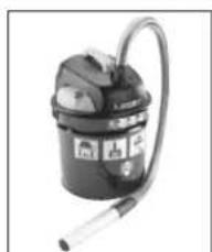
- Must be performed using a vacuum cleaner (see optional extras page 57).
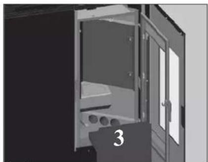
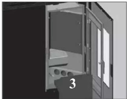
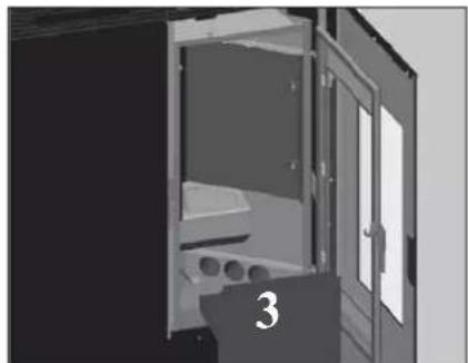
• The whole procedure takes up a few minutes every day. - Open the righthand door, remove the combustion chamber (1 - fig. A) and empty the residue out into the ash pan (3 - fig. C).
• DO NOT EMPTY THE RESIDUE OUT INTO THE PELLET HOPPER.
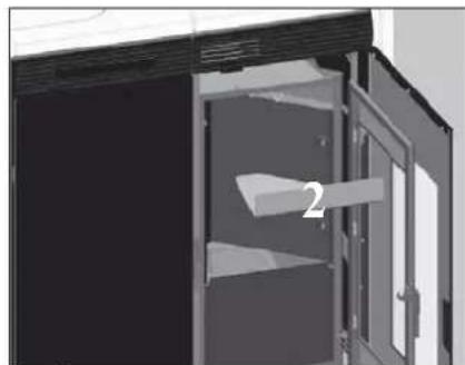
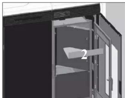
• Take out the ceiling (2 - fig. B) and empty the residue out into the ash pan (3 - fig. C).
• Take out and empty the ash pan (3 - fig. C) into a fireproof container (the ash may still contain hot parts and/or embers). - Remove the combustion chamber or use the spatula to scrape it and clean out any blocked holes on all sides
- Remove the combustion chamber (1 - fig. A) and scrape with a spatula. Clean any obstructions in the apertures.
• Vacuum the combustion chamber holder, clean the edges where the combustion chamber is lodged into its seat. - Clean the glass, if necessary (when cold).
Never vacuum hot ash, it can make the vacuum cleaner breakdown and puts the household rooms at risk of fire
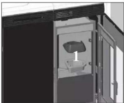
natural_image
Exterior view of a modern office building (no signage)fig. A
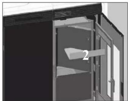
natural_image
Interior view of a cabinet or storage unit with open door and labeled component '2' (no text or symbols beyond label)fig. B
natural_image
Interior view of a room with a door, shelves, and numbered label '3' (no text or symbols on main subject)fig. C
- Involves cleaning the hearth (with a swab) once the ash pan has been removed (3 - fig. C).
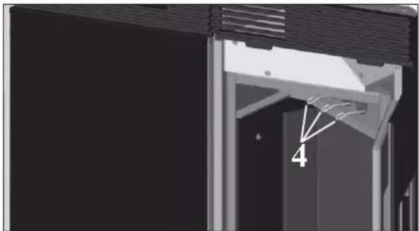
• empty the pellet hopper and clean the base with the vacuum cleaner. - Clean with the swabs (4 - fig. D), vacuum out the 3 pipes below (5 - fig. E)
- Clean out the combustion chamber and smoke extractor (6 - fig. E).
natural_image
Exterior view of a modern building corner with structural beams and a numbered detail (no text or symbols)fig. D
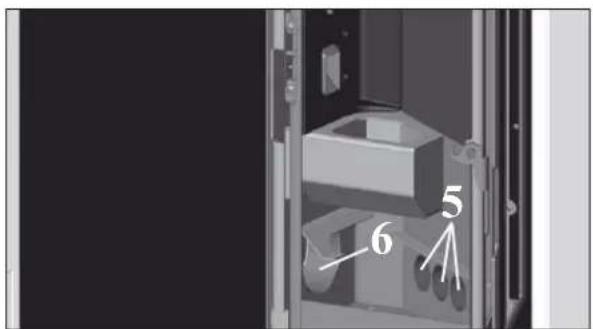
fig. E
MAINTENANCE
SEASONAL MAINTENANCE (implemented by the DEALER)
Consists in:
- Clean the stove internally and externally
- Carefully clean the heat exchange tubes
- Carefully clean and remove dirt from the combustion chamber and the relative compartment
- Clean fans, verify mechanical and clamp loosening
- Clean smoke channel (replace seals on smoke exhaust pipe)
- Clean smoke duct (see weekly cleaning)
- Clean smoke extraction fan compartment, flow sensor and check thermocouple.
- Clean, inspect and scrape any residue from the ignition resistance compartment and if necessary, replace it
- Clean/check the Synoptic Panel
- Visually inspect the electrical wires, connections and power cable
- Clean the pellet hopper and check loosening of the feed screw - gear motor assembly
- Replace the door seal
- Functionality test: load the feed screw, ignite, let it run for 10 minutes and shutdown
If the stove is used very often, it is recommended to clean the smoke channel every 3 months.
ATTENTION !!!
After implementing a normal cleaning procedure, INCORRECT coupling of the upper (A) (figura 1) and lower (B) (figura 1) combustion chambers can compromise the stove's performance.
Therefore, before igniting the stove, ensure that the combustion chambers are correctly coupled as shown in (figura 2).
We remind you that using the stove without cleaning the melting pot, may cause a sudden ignition gas inside the combustion chamber with the consequent breaking of the glass
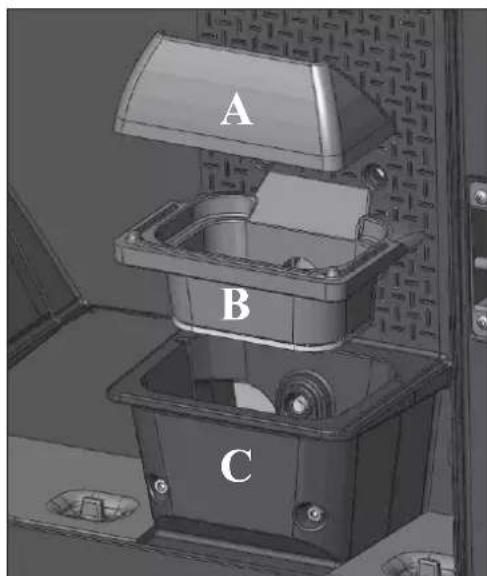
fig. 1
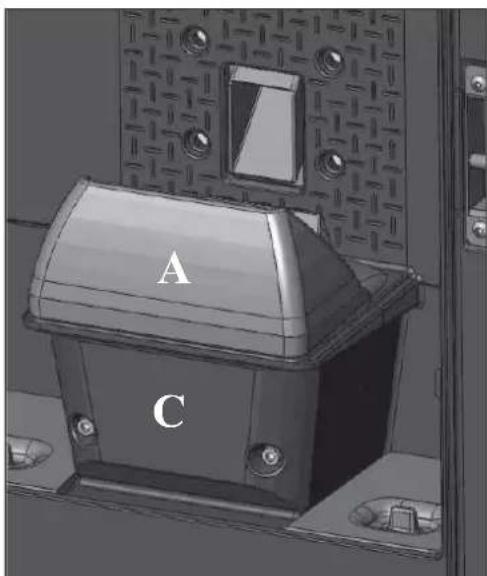
fig. 2
TROUBLESHOOTING TIPS FOR TINY
In the event of problems the stove stops automatically and runs the shutdown process and the display shows text regarding the motivation of the shutdown (see the various alarms below).
Never pull the plug during shutdown on account of malfunction.
Should it block, to restart the stove you will need to allow the turn-off procedure to take place (600 seconds with audible signal), and then press the button 🤊
Do not turn the stove on again before checking the cause of the malfunction and CLEANING/ EMPTYING the crucible.
INDICATION OF POSSIBLE CAUSES OF MALFUNCTION AND INDICATIONS AND REMEDIES:
1) Verific./air flow: (intervenes if the flow sensor detects insufficient combustion air flow).
Turns off for lack of depression
Air flow may be insufficient because the door is open, the door does not close properly (e.g. bad seal), there is an air intake or smoke extraction problem, or the combustion chamber is clogged.
Check:
- door closure;
- combustion air intake duct (clean, paying attention to the flow sensor components);
- clean the flow sensor with dry air (like that used for PC keyboards);
- stove location: it must not be installed against a wall;
- combustion chamber position and cleanliness (clean regularly according to the type of pellet);
- smoke duct (clean);
- installation (if it does not comply with regulations or the smoke outlet has more than 2-3 bends);
If you suspect the sensor is malfunctioning, carry out cold tests. If the conditions are changed (for example by opening the door) and the value does not change, there is a sensor problem.
The no depression alarm may also occur during ignition, since the flow sensor starts monitoring 90 seconds after the ignition cycle begins.
2) Verific./extract.: (intervenes if the smoke extractor revolutions sensor detects an anomaly)
Turns off due to smoke expulsion motor
- Check smoke extractor function (devolution sensor connection) and board.
- Check smoke channel for dirt
- Verify the electrical system and earthing system.
- Check electronic circuit board
3) Stop/Flame: (intervenes if the thermo coupling reports a smoke temperature below a value set, thereby interpreting it as a lack of flame). Turns off due to drop in smoke temperature
Flame may fail for any of the following reasons:
- lack of pellets
- too many pellets have suffocated the flame
- the maximum thermostat has intervened (rare, this only intervenes in the event of excessive smoke temperature)
4) Block_FI/NO Start: (intervenes if a flame fails to appear within a maximum of 15 minutes, or if ignition temperature is not reached). Turns off due to incorrect smoke temperature during ignition
Distinguish either of the following cases:
| The flame has NOT appeared | The flame has appeared but after the wording Ignition, the wording Block_FI/NO Start has appeared. |
| Check:- correct positioning and cleanliness of combustion chamber- resistance function-room temperature (if less than 3°C) and moisture content.- Try to ignite with Diavolina® | Check :- thermo coupling function- ignition temperature set in the parameters |
TROUBLESHOOTING TIPS FOR TINY
5) Black Out: (not a defect of the stove).
Turns off due to lack of electricity
Check electricity connection and drops in voltage.
6) Fault/RC: (intervences if the thermo coupling has failed or is disconnected).
Turns off due to thermo coupling failed or disconnected
Check connection of thermo coupling to board: check function in cold test.
7) smoke °C/high: turns off due to exceeding maximum smoke temperature.
Excessive smoke temperature may depend on: pellet type, anomaly in smoke extraction, smoke channel blocked, incorrect installation, gear motor ‘drift’
Remote control inefficient:
• closer to the receiver of the stove
- check the battery and if necessary, replace it
Output air not hot:
- clean the hearth exchanger.
During ignition, the differential switch trips (DEALER):
- check moisture content of ignition resistance
Does not ignite:
- clean combustion chamber.
"Battery check":
- The stove does not stop but the error appears on the display.
- The buffer battery of the control board needs changing.
NOTA 1
All signals/warnings remain shown until you intervene on the remote control, by pressing the button. Do not use the insert before having eliminated the problem.
NOTA 2
After 1000 kg of pellets consumed, the display flashes the wording 'Mainten.'.
The stove works, but you must call the Dealer out to perform extraordinary maintenance.
TROUBLESHOOTING TIPS FOR KELLY
In the event of problems the stove stops automatically and runs the shutdown process and the display shows text regarding the motivation of the shutdown (see the various alarms below).
Never pull the plug during shutdown on account of malfunction.
To start the stove up again after a shutdown, let the shutdown procedure end (10 minutes marked by a beep) then press the 0/1 key.
Do not turn the stove on again before checking the cause of the malfunction and CLEANING/ EMPTYING the crucible.
INDICATION OF POSSIBLE CAUSES OF MALFUNCTION AND INDICATIONS AND REMEDIES:
1) H1 No Depression (this trips if the flow sensor detects insufficient combustion air flow)
Turns off for lack of depression
Air flow may be insufficient because the door is open, the door does not close properly (e.g. bad seal), there is an air intake or smoke extraction problem, or the combustion chamber is clogged.
Check:
- door closure;
- combustion air intake duct (clean, paying attention to the flow sensor components);
- clean the flow sensor with dry air (like that used for PC keyboards);
- stove location: it must not be installed against a wall;
- combustion chamber position and cleanliness (clean regularly according to the type of pellet);
- smoke duct (clean);
- installation (if it does not comply with regulations or the smoke outlet has more than 2-3 bends);
If you suspect the sensor is malfunctioning, carry out cold tests. If the conditions are changed (for example by opening the door) and the value does not change, there is a sensor problem.
The no depression alarm may also occur during ignition, since the flow sensor starts monitoring 90 seconds after the ignition cycle begins.
2) H2 Smoke expulsion motor failure (this trips if the smoke extraction speed sensor detects a fault)
Turns off due to smoke expulsion motor
- Check smoke extractor function (devolution sensor connection) and board.
- Check smoke channel for dirt
- Verify the electrical system and earthing system.
- Check eletronic circuit board
3) SF (H3) Flame stop (this trips if the thermocouple detects a smoke temperature lower than the value set, which it interprets as the absence of flames) Turns off due to drop in smoke temperature
Flame may fail for any of the following reasons:
- lack of pellets
- too many pellets have suffocated the flame
- the maximum thermostat has intervened (rare, this only intervenes in the event of excessive smoke temperature)
4) AF (H4) No start (intervenes if a flame fails to appear within a maximum of 15 minutes, or if ignition temperature is not reached). Turns off due to incorrect smoke temperature during ignition
Distinguish either of the following cases:
| the flame does NOT appear Flames appear, but AF appears on the display after Ar | |
| Check:- combustion chamber position and cleanliness;- arrival of combustion air in the combustion chamber;- if the heating element is working;- room temperature (if lower than 3°C use a firelighter) and damp.Try to light with a firelighter. | Check: (only by the Dealer)- if the thermocouple is working;- start-up temperature setting in the parameters. |
TROUBLESHOOTING TIPS FOR KELLY
5) H5 Power failure stoppage (not a defect of the stove).
Turns off due to lack of electricity
Check electricity connection and drops in voltage.
6) H6 Thermocouple failure (intervenes if the thermo coupling has failed or is disconnected).
Turns off due to thermo coupling failed or disconnected
Check connection of thermo coupling to board: check function in cold test.
7) H7 Excessive smoke temperature turns off due to exceeding maximum smoke temperature.
Excessive smoke temperature may depend on: pellet type, anomaly in smoke extraction, smoke channel blocked, incorrect installation, gear motor ‘drift’
8) Batt. 1 - Batt. 2
The heating stove will not stop, but this message appears on the display. The buffer battery on the peb must be replaced.
Display-control panel off:
- make sure the power cord is connected check the fuse (on the power socket)
Remote control (optional) not working:
• closer to the receiver of the stove
- check the battery and if necessary, replace it
Outlet air not hot:
- clean heat exchanger from inside the firebox.
During ignition, the differential switch trips (DEALER):
- check moisture content of ignition resistance
Does not ignite:
- clean combustion chamber.
The message is displayed until the 0/1 key on the panel is pressed.
Do not restart the stove until the problem has been looked into and the cause removed.
It is important to tell the Dealer exactly what the panel signals.
CHECK LIST
To be integrated with a complete reading of the technical specifications
Positioning and installing
- Commissioned by a qualified DEALER who has issued the warranty and maintenance manual
• Room ventilation - Only the stove outlet passes through the smoke channel/chimney fluc
• The smoke channel has: a maximum of 2 curves, a maximum 2 horizontal metres - Chimney pot that is high enough to avoid downdraft areas
• The discharge pipes are made of a suitable material (stainless steel is recommended) - When using any flammable materials (e.g. wood), all precautions have been taken to prevent a fire hazard
Usc
• Good quality, dry pellets are used
• The chimney pot and ash compartment are clean and well positioned
• The door is closed properly
- The combustion chamber is inserted properly into the relevant compartment
REMEMBER TO VACUUM THE COMBUSTION CHAMBER BEFORE EACH IGNITION Should ignition fail, DO NOT re-ignite until you have emptied the combustion chamber.
OPTIONAL
TELEPHONE COMBINER FOR REMOTE IGNITION (code 281900)
The stove can be ignited remotely by asking the DEALER to connect the telephone combiner to the serial port behind the stove via the optional cable (TINY code 621240 - KELLY code 620550)
Remote control (KELLY code 633280)
CLEANING ACCESSORIES
natural_image
Bottle of spray cleaning with a spray can (no visible text or symbols)GlassKamin (code 155240)
Used for cleaning the cera-
mic glass
natural_image
Black and white photo of a vacuum cleaner with attached tubing (no visible text or symbols)Ash vacuum cleaner
User for cleaning the
hearth
INFORMATION FOR USERS
In accordance with Art. 13 of the Legislative Decree No. 151, dated 25 July 2005, "Implementation of Directives: 2002/95/EC, 2002/96/EC and 2003/108/EC, pertaining to the reduction of hazardous substances used in electrical and electronic equipment, as well as disposal of waste".
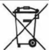
The crossed-out wheeled bin symbol shown on the equipment or on the packaging indicates that the product must be disposed of separately at the end of its useful life.
Therefore, at the end of the equipment's useful life, the user must hand in the equipment to suitable collection facilities for electrical and electronic waste, or return it to the retailer when a new, equivalent appliance is purchased in a ratio of one to one.
Madame, Monsieur,
2006/95/CEE - Directive Basse Tension
natural_image
Close-up of a white plastic hose attached to a dark surface, with no visible text or symbols.CARACTERISTIQUES
natural_image
Technical line drawing of a rectangular industrial or storage unit with ventilation grilles and mounting feet (no text or symbols)Fig. 3
Fig. 2
natural_image
Technical line drawings of a mechanical component with two views (top and side), labeled H, showing internal grid patterns (no text or symbols beyond labels)Fig. 5
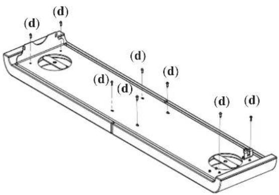
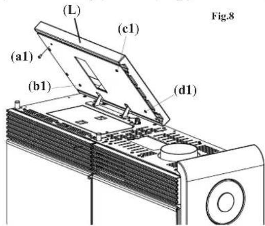
Fig. 6
EVACUATION DES FUMEES
INSTALLATION
SORTIE DES FUMÉES
natural_image
Mechanical device labeled 'G' showing internal components and a base, no readable text or symbols beyond label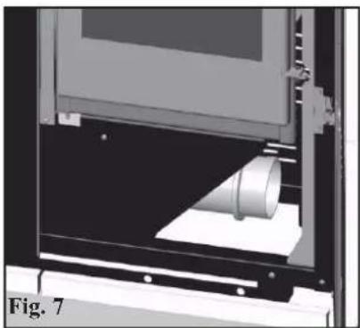
natural_image
3D rendering of a mechanical device with a cylindrical component inserted, labeled Fig. 7 (no text or symbols on the diagram itself)PRISE D'AIR
natural_image
Diagram of a device with two vertical pipes and a labeled top, showing airflow or fluid flow direction (no text or symbols on the diagram itself)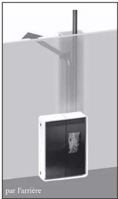
natural_image
Exterior view of a modern office building (no signage)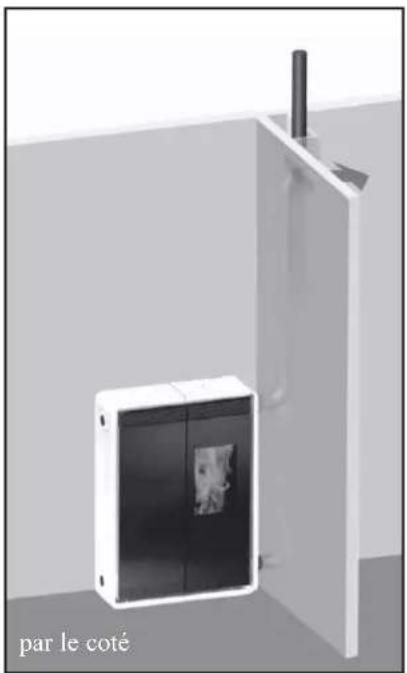
natural_image
3D rendering of a white cabinet with a black panel and a vertical pipe inserted, labeled 'par le coté' at the bottom (no other text or symbols)INSTRUCTIONS D'UTILISATION
Avant d'allumer.
natural_image
3D diagram of an open device with a star-shaped internal component, labeled 'fig. 1' (no text or symbols on the diagram itself)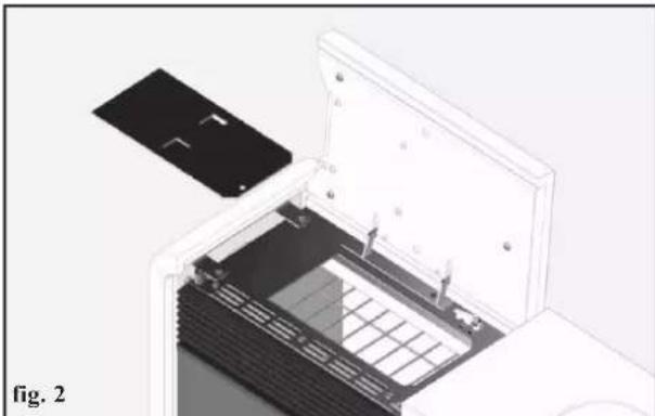
natural_image
3D cutaway view of an electronic device showing internal components and a battery cover (no text or symbols visible)natural_image
Close-up of a gray handheld electronic device with control buttons and a display screen (no visible text or symbols)
natural_image
Black medical device with 'EDIL KANNA' label and medical symbol on screen (no readable text beyond branding)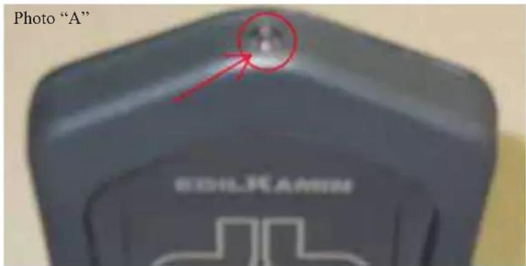
CARACTÉRISTIQUES TECHNIQUES
When a button is pressed, the backlight goes on, which indicates that the remote control is transmitting the signal. The "beep" emitted by the stove confirms its reception.
PORTÉE
Remote control receiver
natural_image
Exterior view of a desktop computer tower case with ventilation grilles and ventilation ducts (no visible text or labels)natural_image
Interior view of a modular kitchen or storage unit with a door, vent, and internal compartments (no visible text or symbols)fig. A
natural_image
Interior view of a cabinet or storage unit with open door and shelf, no visible text or symbolsfig. B
natural_image
Interior view of a double door with visible door frame and window, labeled with number 3 (no text or symbols on the door itself)fig. C
ENTRETIEN HEBDOMADAIRE
natural_image
Exterior view of a modern building corner with structural beams and a numbered detail (no signage or text)fig. D
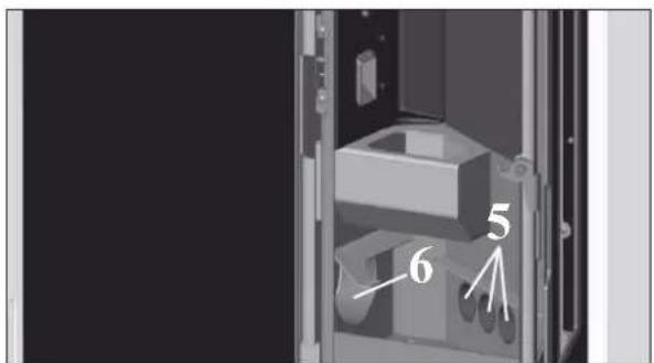
fig. E
ENTRETIEN
ENTRETIEN SAISONNIER (par le revendeur)
Consiste en:
- clean combustion chamber.
- clean combustion chamber.
natural_image
Bottle of spray cleaning material with spray nozzle (no visible text or symbols)natural_image
Black and white photo of a vacuum cleaner with attached tubing (no visible text or symbols)natural_image
Close-up of a white cable with a black headband on a metal panel (no text or symbols visible)CARACTERÍSTICAS
natural_image
Technical line drawing of a rectangular industrial or laboratory device with ventilation grilles and mounting feet (no text or symbols)Fig. 3
Fig. 2

natural_image
Technical line drawings of a mechanical component with two views (top and side), labeled H, showing internal grid structures (no text or symbols beyond labels)Fig. 5
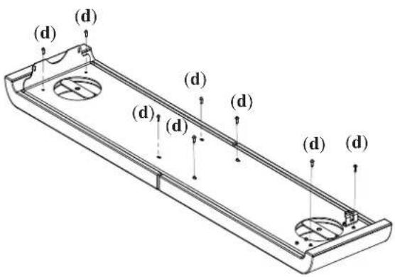
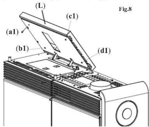
Fig. 6
INSTALACIÓN
SALIDA DE HUMOS
natural_image
Mechanical device labeled 'G' showing internal components and housing (no readable text or symbols beyond label)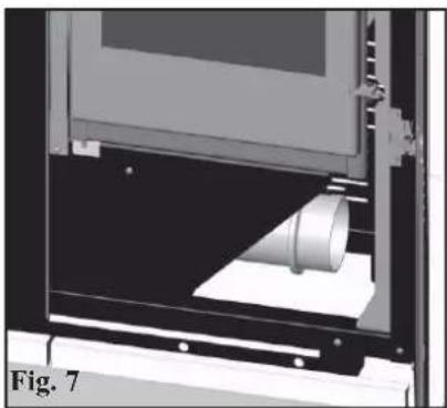
natural_image
3D rendering of a mechanical device with a cylindrical component inserted, labeled Fig. 7 (no text or symbols on the device itself)TOMA DE AIRE
natural_image
Diagram of a portable electronic device with two vertical pipes and a central panel, labeled 'por la tapa' (no other text or symbols)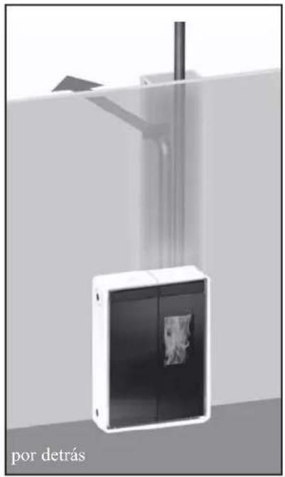
natural_image
Exterior view of a white cabinet with a black panel and a vertical rod, labeled 'por el lado' at the bottom (no other text or symbols)INSTRUCCIONES DE USO
Antes de encender.
natural_image
3D diagram of an open device with a star-shaped internal component, labeled 'fig. 1' (no text or symbols on the diagram itself)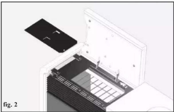
natural_image
3D diagram of an open device with a black panel inserted, showing internal components and a grid pattern (no text or symbols)ATENCIÓN:
natural_image
Close-up of a gray handheld electronic device with a digital display showing '25s' and control buttons (no readable text beyond symbols)
natural_image
Black handheld electronic device with a medical cross symbol and control buttons (no readable text or symbols beyond branding)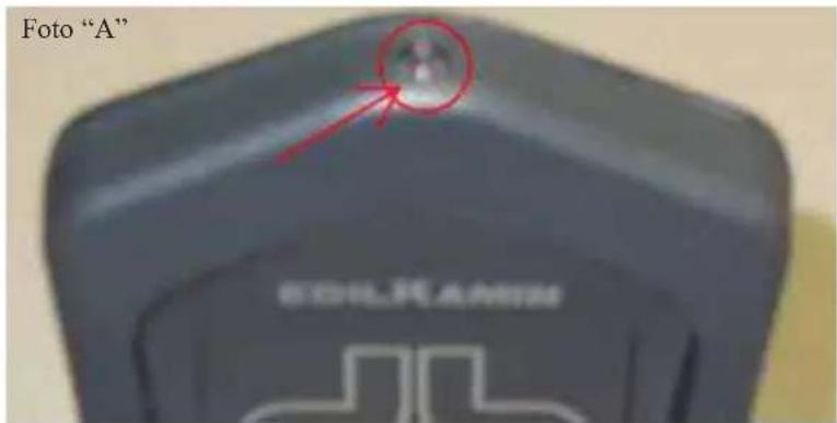
CARACTERÍSTICAS TÉCNICAS
natural_image
Exterior view of a desktop computer tower case with ventilation grilles and ventilation ducts (no visible text or labels)natural_image
Interior view of a modern office or gas station with a door, cabinet, and storage unit (no visible text or symbols)fig. A
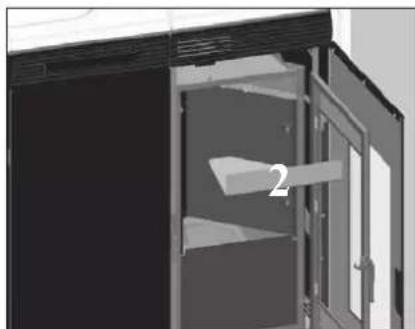
natural_image
Interior view of a cabinet with open door and shelf, no visible text or symbolsfig. B
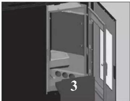
natural_image
Interior view of a door with open door, showing structural components and a numbered label '3' (no text or symbols on the door itself)fig. C
MANTENIMIENTO SEMANAL
natural_image
Exterior view of a modern building corner with structural beams and a numbered detail (no visible text or symbols)fig. D
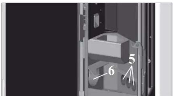
fig. E
MANUTENCIÓN
LIMPIEZA ESTACIONAL (a cargo del DISTRIBUIDOR)
Consiste en la:
natural_image
Bottle of spray cleaning with a spray can (no visible text or symbols)natural_image
Black and white photo of a vacuum cleaner with attached tubing (no visible text or symbols)Bidón aspira
natural_image
Close-up of a white rope tied with a black object on a perforated metal surface (no text or symbols visible)MERKMALE
natural_image
Technical line drawing of a rectangular industrial or laboratory device with ventilation grilles and mounting feet (no text or symbols)Fig. 3
Fig. 2
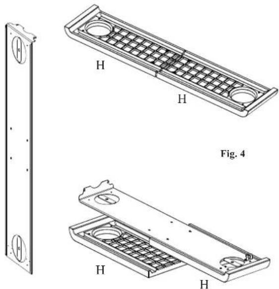
natural_image
Technical drawings of a mechanical component with two views and labeled H, showing internal structure (no text or symbols beyond labels)Fig. 5
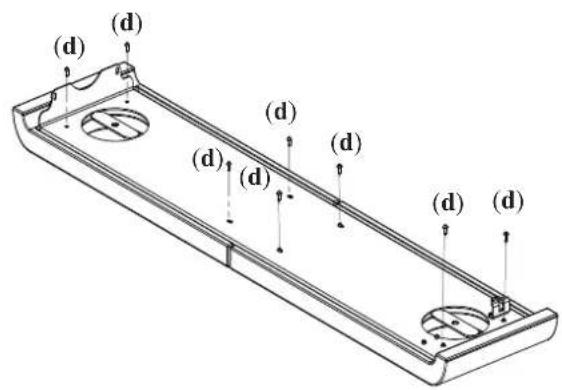
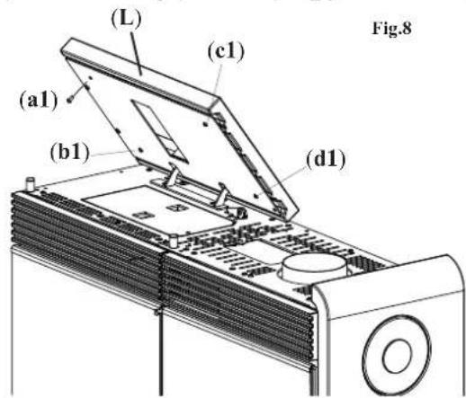
Abb. 6
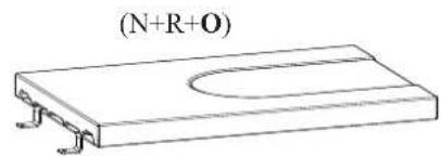
Fig. 10
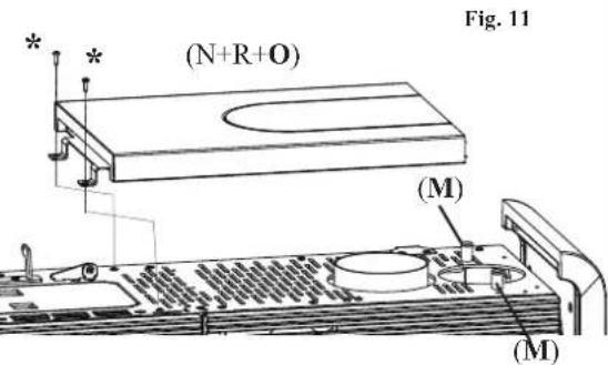
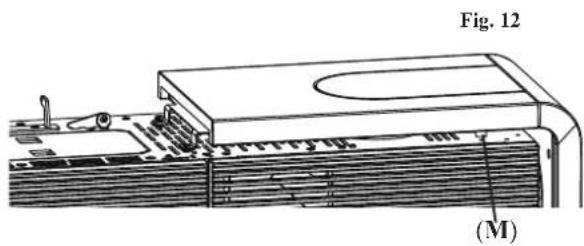
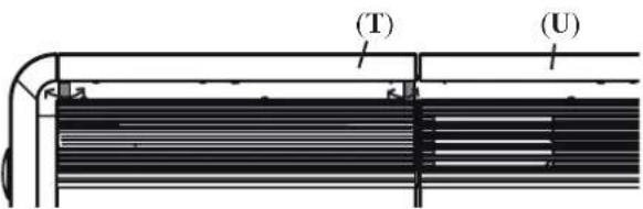
Fig. 13

natural_image
Close-up of a mechanical device with labeled component G, no visible text or symbols beyond label (no readable document text)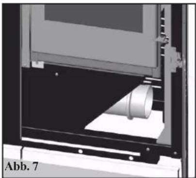
natural_image
Mechanical assembly diagram showing a cylindrical component inserted into a housing (no text or symbols visible)LUFTEINLASS
natural_image
Diagram of a device mounted on an oberteil panel with two vertical pipes, no text or symbols present.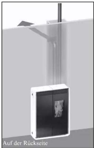
natural_image
Exterior view of a modern office building (no signage)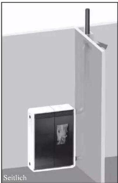
natural_image
Exterior view of a modern office building (no signage)natural_image
Interior view of an electronic device showing a closed panel with a flower symbol on the cover (no text or labels visible)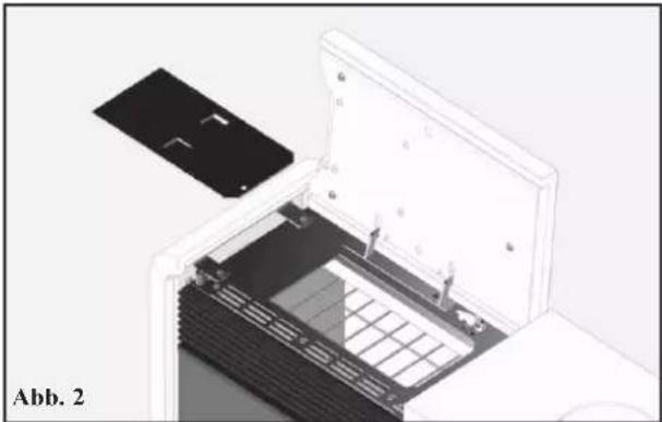
natural_image
3D diagram of an open printer with a black plastic cover and grid-patterned internal structure, labeled 'Abb. 2' (no text or symbols on the diagram itself)ACHTUNG :
natural_image
Close-up of a gray handheld electronic device with a digital display showing '255' and control buttons (no readable text beyond symbols)
natural_image
3D rendered image of a black handheld electronic device with control buttons and a display screen (no readable text or symbols)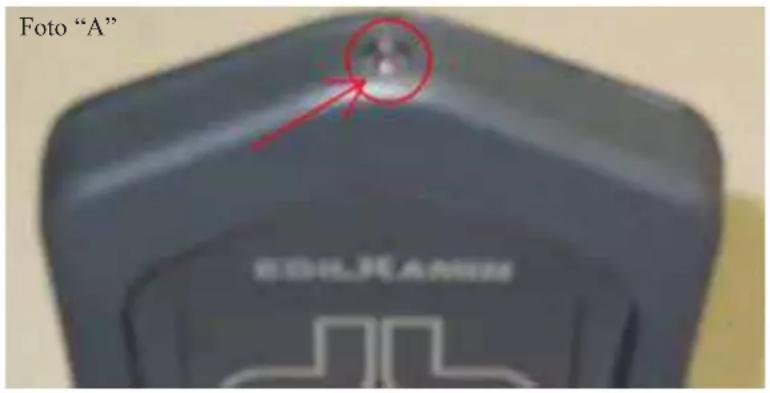
TECHNISCHE MERKMALE
natural_image
Exterior view of a server rack unit with ventilation grilles and ventilation ducts (no visible text or symbols)Display-Angaben
natural_image
Interior view of a double door with a highlighted opening and internal structure (no text or symbols visible)Abb. A
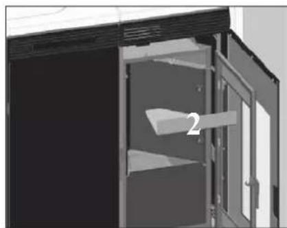
natural_image
Interior view of a cabinet with open door and shelf, no visible text or symbolsAbb. B Abb. C
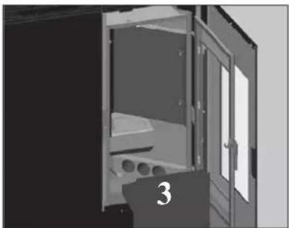
natural_image
Interior view of a double door with open door, showing internal compartments and ventilation ducts (no text or symbols)natural_image
Exterior view of a modern building entrance with a triangular roof and window (no signage or text)Abb. D Abb. E
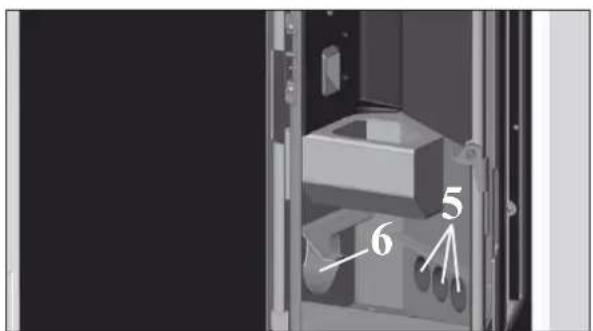
WARTUNG
natural_image
Close-up of a mechanical device with labeled parts A and C, mounted on a panel (no readable text beyond labels)Abb. 2
natural_image
Bottle of spray cleaning with a spray gun (no visible text or symbols)natural_image
Black and white photo of a vacuum cleaner with attached tubing (no visible text or symbols)natural_image
Close-up of a white cable with a black handle attached to a dark surface, possibly part of a vehicle or industrial component (no visible text or symbols)EIGENSCHAPPEN
BESCHERMINGSINSTALLATIES
natural_image
Technical line drawing of a rectangular industrial or laboratory device with ventilation grilles and control panels (no text or symbols)Fig. 2
Fig. 3
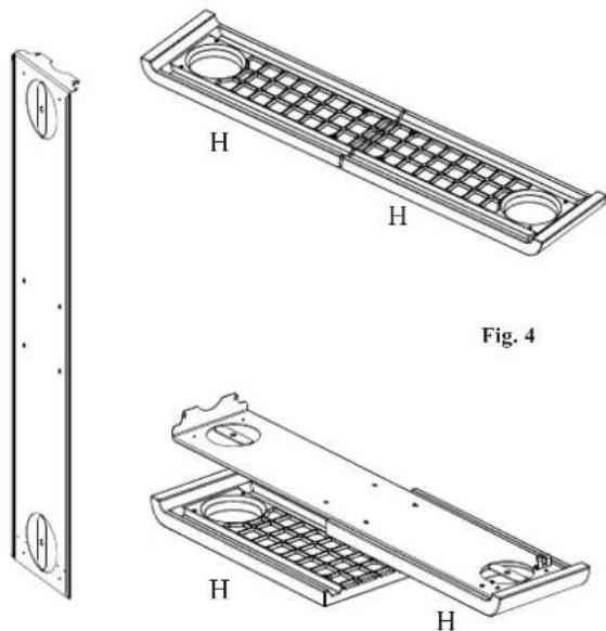
natural_image
Technical drawings of a mechanical component with two views and labeled H, showing internal structure (no text or symbols beyond labels)Fig. 5
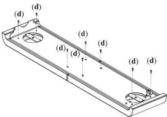
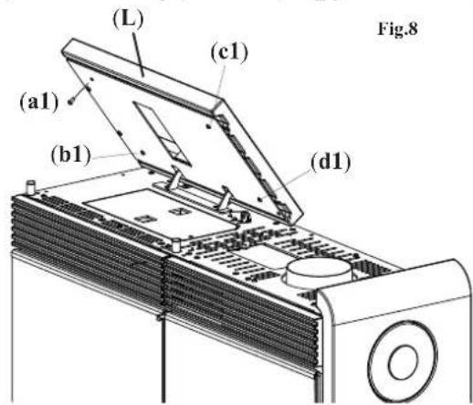
Afb. 6
natural_image
Close-up of a mechanical device with labeled component 'G' and section marker 'Afb. 6' (no readable text or symbols beyond labels)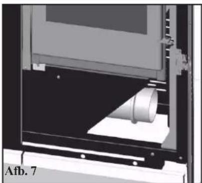
natural_image
3D rendering of a mechanical device with a cylindrical component inserted, labeled 'Afb. 7' at bottom left (no other text or symbols visible)LUCHTINLAAT
natural_image
Diagram of a bovenkant air duct system with two vertical pipes and a control panel, no text or symbols present.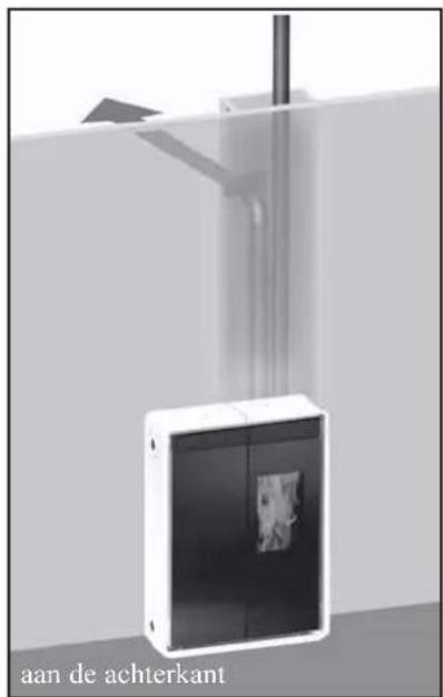
natural_image
Exterior view of a modern office building (no signage)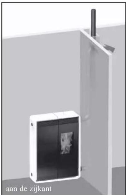
natural_image
3D rendering of a white cabinet with a black panel and a small inset image, mounted on a wall (no text or symbols visible)natural_image
3D cutaway view of an open electronic device showing internal components and a star-shaped symbol on the screen (no text or labels)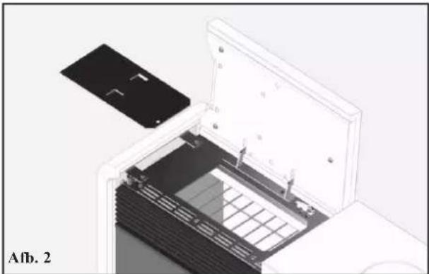
natural_image
3D diagram of an open electronic device with a black panel and grid structure, labeled 'Afb. 2' (no text or symbols on the device itself)LET OP:
natural_image
Close-up of a gray handheld electronic device with four rotary buttons (A, M, O, S) and a digital display showing '25s' (no readable text or symbols beyond basic labels)
DRUK DE TOETS NOOIT MEERDERE KEREN IN

Systeem pelletreserve
resterende Kg in de tank
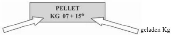
natural_image
Black medical device with digital display and control buttons (no visible text or symbols)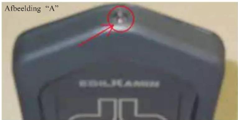
natural_image
Exterior view of a server unit with ventilation grilles and ventilation ducts (no visible text or symbols)natural_image
Interior view of a laboratory or storage unit with a central container and open door (no visible text or symbols)Afb. A
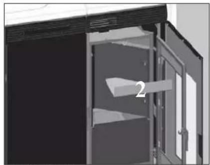
natural_image
Interior view of a double-door refrigerator with open door and shelf, no visible text or symbolsAfb. B Afb. C
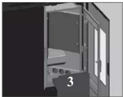
natural_image
Interior view of a double door with visible door, windows, and internal compartments (no text or symbols)WEKELIJKS ONDERHOUD
natural_image
Exterior view of a modern building corner with structural beams and a numbered detail (no text or symbols)Afb. D Afb. E
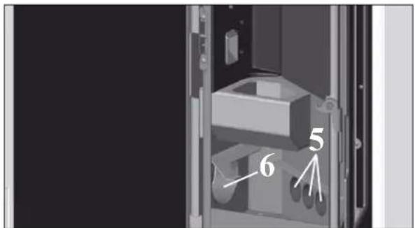
ONDERHOUD
SEIZOENSGEBONDEN ONDERHOUD (door uw Dealer)
Bestaat uit:
natural_image
Bottle of spray cleaning material with spray nozzle (no visible text or symbols)natural_image
Black industrial vacuum cleaner with attached pipe and valve (no visible text or symbols)natural_image
Exterior view of a modern industrial appliance with black panels and a visible internal combustion chamber (no text or symbols)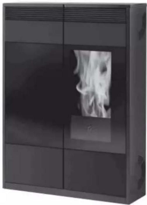
natural_image
Exterior view of a modern black appliance cabinet with visible flames inside (no text or symbols)MONTAVIMO, EKSPLOATAVIMO IR PRIEŽIŪROS INSTRUKCIJOS
Mieli ponai/ponios,
natural_image
Close-up of a car's hood with a white plastic clip and circular emblem (no visible text or symbols)natural_image
Close-up of a mechanical device with labeled parts (G, H) and '3 p av.' annotation, no readable text or symbols beyond labelsŠILTO ORO IŠĖJIMO VAMZDŽIO
PRIJUNGIMAS DEŠINĖJE PUSĖJE
natural_image
3D mechanical component with labeled parts (I and L) and a 4-pav indicator, no readable text or symbols beyond labelsnatural_image
Close-up of a mechanical component with a cylindrical part and a labeled section '6 pav.' (no readable text or symbols beyond label)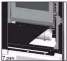
natural_image
Close-up of a mechanical device with a cylindrical component inserted, labeled '7 pav.' (no other text or symbols visible)ORO IÈJIMO ANGA
natural_image
Close-up of a mechanical assembly with pipes and components, no visible text or symbols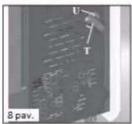
KIT 8(kodas 297360)
Pastaba: PIRMOJI LANKSČIOJO VAMZDŽIO DALIS TURI BŪTI VISIŠKAI „ATSIPALAIDAVUSI“, KAD BŪTŲ PAŠALINTOS GOFRUOTUMAS. TOKIU BŪDU VIDINIS SKERSMUO ŠIEK TIEK PADIDĖS PAGERINANT ĮVESTI.
natural_image
Exterior view of a wall-mounted electrical enclosure with vertical metal lines and a small display panel (no text or symbols visible)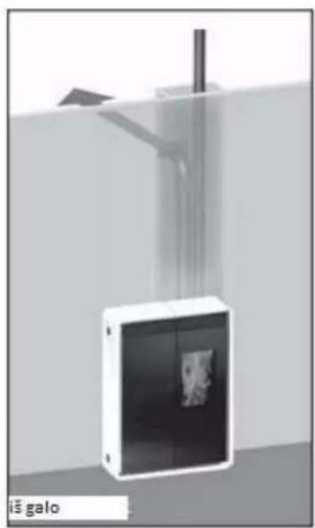
natural_image
3D rendering of a wall-mounted device with a vertical pipe and mounting bracket, labeled 'imgalo' at bottom (no other text or symbols)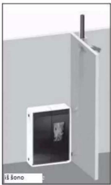
natural_image
Exterior view of a white cabinet or enclosure unit with a black panel and a vertical chimney, no visible text or symbols.NAUDOJIMO INSTRUKCIJOS
Prieš uždegimą
natural_image
Black remote control device with a digital display and control buttons (no visible text or symbols)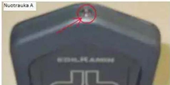
TECHNINÈS CHARAKTERISTIKOS
natural_image
Interior view of a double door with a small inset image showing a device (no visible text or symbols)Apav.
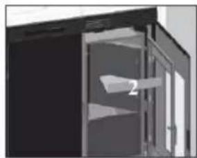
natural_image
Exterior view of a modern office building (no signage)8 pav.
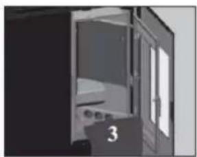
natural_image
Exterior view of a modern office building (no signage)Cpav.
SAVAITINÉ PRIEŽIŪRA
natural_image
Exterior view of a building entrance with a triangular structure and a numbered marker (4), no visible text or symbols.Dpav.
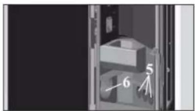
natural_image
Interior view of a server room with numbered components (no readable text or symbols)Epav,
SEZONINÉ PRIEŽIŪRA (atlieka ATSTOVAS)
Ją sudaro:
natural_image
3D diagram of a mechanical device with labeled parts A, B, and C (no text or symbols beyond labels)1 pav.
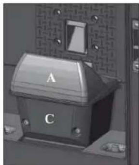
natural_image
Close-up of a mechanical control box with labeled terminals A and C, mounted on a metal frame (no visible text or symbols beyond labels)2 pav.
GEDIMU ŠALINIMO REKOMENDACIJOS TINY MODELIAMS
- CARATTERISTICHE
- COLLEGAMENTO USCITA ARIA CALDA DAL TOP
- INSTALLAZIONE
- USCITA FUMI
- COLLEGAMENTO USCITA FUMI DAL TOP
- PRESA D'ARIA
- ISTRUZIONI D' USO
- Prima di accendere.
- CARATTERISTICHE TECNICHE
- MANUTENZIONE
- NOTE
- SAFETY INFORMATION
- DIMENSIONS AND FINISHINGS
- TINY
- KELLY
- FEATURES
- SERIAL PORT
- BACKUP BATTERY
- ROOM TEMPERATURE SENSOR
- COVERING ASSEMBLY
- TINY (the KELLY model comes pre-assembled)
- Fig. 1
- Note:
- SIDE COVERING ASSEMBLY: CERAMIC COMPONENTS
- Fig. 3/4
- Fig. 5
- LEFT TOP ASSEMBLY
- RIGHT TOP ASSEMBLY
- LOWER INSERT ASSEMBLY
- POSITIONING
- INSTALLATION
- VERIFY COMPATIBILITY WITH OTHER DEVICES
- VERIFY THE POWER SUPPLY CONNECTION (the plug must be accessible)
- FIRE PREVENTION SAFETY DISTANCES
- AIR INTAKE
- SMOKE OUTLET
- CHIMNEY POT
- HOT AIR CIRCULATION
- CONNECTING THE WARM AIR OUTLET ON THE TOP
- CONNECTING THE WARM AIR OUTLET ON THE RIGHT SIDE
- CONNECTING THE WARM AIR OUTLET ON THE BACK
- WARM AIR DISTRIBUTION CONTROL
- N.B.: IT IS ADVISABLE TO USE CHANNELLING PIPES OF A MAXIMUM LENGTH OF 3 M WITH 2 CURVES.
- SMOKE EXHAUST
- CONNECTING THE SMOKE EXHAUST PIPE ON THE TOP
- CONNECTING THE SMOKE EXHAUST PIPE ON THE BACK
- CONNECTING THE SMOKE EXHAUST PIPE ON THE SIDE
- KIT 8 (code 297360)
- INSTRUCTIONS FOR USE
- Before igniting.
- Filling the pellet hopper
- THE CERAMIC TOP IS VERY FRAGILE. HANDLE IT WITH CARE WHEN OPENING AND CLOSING IT.
- ATTENTION:
- NOTE regarding the fuel.
- TINY MODEL SERIES RADIO REMOTE CONTROL
- Key to buttons and display:
- DO NOT PRESS THE BUTTON MORE THAN ONCE
- CONTINUED: TINY model series radio remote control
- Filling the cochlea.
- Automatic igniting.
- Manual igniting.
- POWER REGULATION
- - Remote control manual operation
- - Remote control automatic operation
- Turning off
- OPERATIONS THAT CAN ONLY BE CARRIED OUT BY REMOTE CONTROL
- Clock regulation
- Weekly timer
- Changing pellet loading
- Notes on flame variability
- CONTINUED: TINY model series radio remote control RESERVE WARNING
- st ignition/test by the Edilkamin authorised Dealer
- Pellet reserve system
- EMERGENCY BUTTON
- RADIO ANTENNA
- OPTIONAL REMOTE CONTROL code 633280 FOR KELLY MODEL
- TECHNICAL CHARACTERISTICS
- CAPACITY
- BATTERY LIFE
- Synoptic panel for the Kelly model
- Display unit messages
- SCREW FEEDER LOADING
- Automatic ignition
- Manual ignition
- CONTINUED: Synoptic panel for the Kelly model
- - Automatic mode
- Note on flame variability
- Switching off
- WEEKLY TIME PROGRAMMER BUILT INTO PANEL
- Setting the clock
- Enabling programmes
- Setting a programme (e.g. Pr01)
- MAINTENANCE
- DAILY MAINTENANCE
- SEASONAL MAINTENANCE (implemented by the DEALER)
- ATTENTION !!!
- TROUBLESHOOTING TIPS FOR TINY
- INDICATION OF POSSIBLE CAUSES OF MALFUNCTION AND INDICATIONS AND REMEDIES:
- Turns off for lack of depression
- Turns off due to smoke expulsion motor
- Remote control inefficient:
- NOTA 1
- NOTA 2
- TROUBLESHOOTING TIPS FOR KELLY
- Display-control panel off:
- Remote control (optional) not working:
- Outlet air not hot:
- During ignition, the differential switch trips (DEALER):
- Does not ignite:
- CHECK LIST
- To be integrated with a complete reading of the technical specifications
- Positioning and installing
- Usc
- OPTIONAL
- TELEPHONE COMBINER FOR REMOTE IGNITION (code 281900)
- CLEANING ACCESSORIES
- CARACTERISTIQUES
- EVACUATION DES FUMEES
- SORTIE DES FUMÉES
- PRISE D'AIR
- INSTRUCTIONS D'UTILISATION
- Avant d'allumer.
- CARACTÉRISTIQUES TECHNIQUES
- PORTÉE
- ENTRETIEN HEBDOMADAIRE
- ENTRETIEN
- ENTRETIEN SAISONNIER (par le revendeur)
- CARACTERÍSTICAS
- INSTALACIÓN
- SALIDA DE HUMOS
- TOMA DE AIRE
- INSTRUCCIONES DE USO
- Antes de encender.
- ATENCIÓN:
- CARACTERÍSTICAS TÉCNICAS
- MANTENIMIENTO SEMANAL
- MANUTENCIÓN
- LIMPIEZA ESTACIONAL (a cargo del DISTRIBUIDOR)
- MERKMALE
- Abb. 6
- LUFTEINLASS
- ACHTUNG :
- TECHNISCHE MERKMALE
- Display-Angaben
- WARTUNG
- EIGENSCHAPPEN
- Afb. 6
- LUCHTINLAAT
- LET OP:
- DRUK DE TOETS NOOIT MEERDERE KEREN IN
- Systeem pelletreserve
- WEKELIJKS ONDERHOUD
- ONDERHOUD
- SEIZOENSGEBONDEN ONDERHOUD (door uw Dealer)
- ŠILTO ORO IŠĖJIMO VAMZDŽIO
- PRIJUNGIMAS DEŠINĖJE PUSĖJE
- ORO IÈJIMO ANGA
- KIT 8(kodas 297360)
- NAUDOJIMO INSTRUKCIJOS
- Prieš uždegimą
- TECHNINÈS CHARAKTERISTIKOS
- SAVAITINÉ PRIEŽIŪRA
- SEZONINÉ PRIEŽIŪRA (atlieka ATSTOVAS)
- Ją sudaro:
- GEDIMU ŠALINIMO REKOMENDACIJOS TINY MODELIAMS
Brand : EDILKAMIN
Model : TINY
Category : Oven