20301 - Model making LGB - Free user manual and instructions
Find the device manual for free 20301 LGB in PDF.
User questions about 20301 LGB
0 question about this device. Answer the ones you know or ask your own.
Ask a new question about this device
Download the instructions for your Model making in PDF format for free! Find your manual 20301 - LGB and take your electronic device back in hand. On this page are published all the documents necessary for the use of your device. 20301 by LGB.
USER MANUAL 20301 LGB
natural_image
Side profile of an orange electric locomotive with 'E1' and 'Stadtwerke' branding, mounted on railway tracks (no additional text or symbols)| Table of Contents: | Page |
| Safety Notes 8 | |
| Important Notes 8 | |
| Functions | 8 |
| Information about operation 8 | |
| Multi-Protocol Operation 9 | |
| Service and maintenance 10 | |
| Controllable Functions 10 | |
| Table for CV 11 | |
| Spare parts 29 |
- This model may only be used with the operating system designed for it.
- Use only switched mode power supply units and transformers that are designed for your local power system.
- This locomotive must never be supplied with power from more than one power pack.
- Pay close attention to the safety notes in the instructions for your operating system.
• Not for children under the age of 15. - WARNING! Sharp edges and points required for operation.
- WARNING! This product contains magnets. Swallowing more than one magnet may cause death in certain circumstances. If necessary, see a doctor immediately.
Important Notes
- The operating instructions are a component part of the product and must therefore be kept in a safe place as well as included with the product, if the latter is given to someone else.
- The warranty card included with this product specifies the warranty conditions.
- Please see your authorized LGB dealer for repairs or spare parts.
- Disposing: www.maerklin.com/en/imprint.html
Functions
- This model is designed for operation on LGB two-rail DC systems with conventional LGB DC train controllers or power packs (DC, 0 - 24 volts).
• Factory-installed multiple protocol decoder (DC, DCC, mfx). - The model is programmed with locomotive address 03 for use with the LGB Multi Train System (DCC). The locomotive is automatically recognized in operation with mfx.
• Volume can be changed for the sound effects - Mfx technology for the Mobile Station/Central Station. Name set at the factory: Stadtwerke Lok1
- The functions can be activated only in parallel. Serial activation of the functions is not possible (Please note here the instructions for your controller).
General Note to Avoid Electromagnetic Interference:
A permanent, flawless wheel-rail contact is required in order to guarantee operation for which a model is designed. Do not make any changes to current-conducting parts.
Mode of Operation Switch
This locomotive has a mode of operation switch.
Pos. 0 Locomotive stopped without current
Pos. 1 Locomotive motor, lighting, and sound turned on
Pos. 2 & 3 Same as Pos. 1
Sound
The bell and horn can be activated with the LGB sound activation magnet (17050) included with the locomotive. The activation magnet can be clipped into place between the ties of most LGB track sections.
The magnet is positioned to the side under the LGB logo cast into the plastic cover.
Place the magnet on one side to activate the horn when the locomotive passes over this spot. The bell will sound when the magnet is placed on the other side.
This decoder can also be operated on analog layouts or areas of track that are analog. The decoder recognizes alternating current (DC) and automatically adapts to the analog track voltage. All functions that were set under mfx or DCC for analog operation are active (see Digital Operation).
The built-in sound functions come from the factory inactive for analog operation.
Digital Operation
The decoders are multi-protocol decoders. These decoders can be used under the following digital protocols: mfx or DCC.
The digital protocol with the most possibilities is the highest order digital protocol. The sequence of digital protocols in descending order is:
Priority 1: mfx; Priority 2: DCC; Priority 3: DC
Note: Digital protocols can influence each other. For trouble-free operation, we recommend deactivating those digital protocols not needed by using CV 50. Deactivate unneeded digital protocols at this CV if your controller supports this function.
If two or more digital protocols are recognized in the track, the decoder automatically takes on the highest order digital protocol, example: mfx/DCC; the decoder takes on the mfx digital protocol (see previous table).
Note: Please note that not all functions are possible in all digital protocols. Several settings for functions, which are supposed to be active in analog operation, can be done under mfx and DCC.
Notes on digital operation
- The operating instructions for your central unit will give you exact procedures for setting the different parameters.
- The values set at the factory have been selected for mfx in order to guarantee the best possible running characteristics.
Adjustments may have to be made for other operating systems.
mfx Protocol
Addresses
- No address is required; each decoder is given a one-time, unique identifier (UID).
- The decoder automatically registers itself on a Central Station or a Mobile Station with its UID-identifier.
Programming
- The characteristics can be programmed using the graphic screen on the Central Station or also partially with the Mobile Station.
- All of the Configuration Variables (CV) can be read and programmed repeatedly.
- The programming can be done either on the main track or the programming track.
- The default settings (factory settings) can be produced repeatedly.
• 14/28 or 126 speed levels can be set.
As delivered from the factory, the locomotive is programmed for 28 speed levels. If your locomotive controller is set for 14 speed levels, then the locomotive must be reprogrammed (CV 29, Bit 1). - Function mapping: Functions can be assigned to any of the function buttons with the help of the 60212 Central Station (with limitations) and with the 60213/60214/60215 Central Station (See help section in the Central Station).
• See the CV description for the DCC protocol for additional information.
DCC Protocol
Addresses
- Short address – long address – multiple unit address
- Address range:
1 - 127 for short address and multiple unit address,
1 - 10239 for long address
- Every address can be programmed manually.
- Short or long address is selected by means of CV 29 (Bit 5).
- A multiple unit address that is being used deactivates the standard address.
Programming
- The characteristics can be changed repeatedly using the Configuration Variables (CV).
- The CV numbers and the CV values are entered directly.
- The CVs can be read and programmed repeatedly. (Programming is done on the programming track.)
- The CVs can be programmed in any order desired. (PoM - Programming can be done on the main track). PoM is not possible with CVs CV 1, 17, 18, and 29. PoM must be supported by your central controller (Please see the description for this unit.).
- The default settings (factory settings) can be produced repeatedly.
• 14 or 28/126 speed levels can be set. - All of the functions can be controlled according to the function mapping (see CV description).
• See the CV description for the DCC protocol for additional information.
We recommend that in general programming should be done on the programming track.
SERVICE
Lubrication
Oil each of the axle bearings now and then with a drop of Märklin oil (7149).
Changing Light Bulbs (E130023)
Remove the ring around the lantern lens. Carefully pry the lens away from the lantern.
Using tweezers, remove and replace the bulb. Reassemble.
| Controllable Functions | ||
| Lighting1 | LV + LR | |
| Sound effect: Horn 1 Sound 1 | ||
| Sound effect: Squealing brakes off 2 BS | ||
| Sound effect: Short Horn 3 Sound 2 | ||
| 4 | ||
| Sound effect: Conductor whistle | 5 Sound 4 | |
| Sound effect: Operating sounds1,2 | 6 | FS |
| Sound effect: Bell 7 Sound 3 | ||
| Sound on/off 8 Sound 8 | ||
| ABV, off 9 | ||
| 10 | ||
| Rear headlights off 11 | ||
| Headlights in the front off 12 | ||
| Sound effect: Blower 13 Sound 9 | ||
| Sound effect: Air pump 14 Sound 11 | ||
| Sound effect: sanding | 15 Sound 15 | |
| Sound effect: Coupling together (buffer to buffer) | 16 Sound 16 | |
| Sound effect: Main relay | 17 Sound 8 | |
| Sound effect: Contactor | 18 Sound 17 | |
| Sound effect: Letting off air | 19 Sound 14 | |
^1 active in analog operation
^2 with random sounds
| Register | Assignment Range Default | ||
| 1 Address 1 – 127 3 | |||
| 2 Minimum speed 0 – 255 7 | |||
| 3 Acceleration delay 0 – 255 4 | |||
| 4 Braking delay 0 – 255 4 | |||
| 5 Maximum speed 0 – 255 180 | |||
| 8 Reset 8 159 | |||
| 13 Function F1 – F8 with alternative track signal 0 – 255 32 | |||
| 14 Function FL, F9 – F15 with alternative track signal 0 – 255 1 | |||
| 17 Expanded address, higher value byte | 192 – 231 | 192 | |
| 18 Expanded address, lower value byte | 0 – 255 128 | ||
| 19 Multiple unit operation address | 0 – 255 0 | ||
| 21 Functions F1 – F8 with multiple unit operation | 0 – 255 0 | ||
| 22 Function FL, F9 – F15 with multiple unit operation | 0 – 255 0 | ||
| 27 | Bit 4: Braking mode voltage against the direction of travel | 0/16 | 16 |
| Bit 5: Braking mode voltage with the direction of travel | 0/32 | ||
| 29 | Bit 0: Direction normal/inverted | 0/1 | 6 |
| Bit 1: Number of speed levels 14/28(128) | 0/2 | ||
| Bit 2: Analog operation off/on | 0/4 | ||
| Bit 5: short / long address active | 0/32 | ||
| 50 | Alternative Formats | 0/2 | 14 |
| Bit 1: Analog DC | 0/8 | ||
| Bit 3: mfx off/on | |||
| Register | Assignment Range Default | ||
| 60 | Multi-station announcementBit 0 – 3: Number of stationsBit 4: Last announcement changes the sequenceBit 5: Locomotive direction changes the sequenceBit 6: Start for the sequence | 0 – 150/160/320/64 | 30 |
| 63 Total volume | 0 – 255 255 | ||
| 64 Threshold for squealing brakes | 0 – 255 35 | ||
| 67 – 94 | Speed table for speed levels 1 – 28 | 0 – 255 | |
| 112 | Mapping lights in the front, mode | 0 – 21 | 1 |
| 113 | Mapping lights in the front, dimmer | 0 – 255 255 | |
| 114 | Mapping lights in the front, cycle | 0 – 255 20 | |
| 115 | On and Off Delay | 0 – 255 0 | |
| 116 – 143 | Mapping phys. outputs, lights in the rear, Aux 1 – 6, compare 112 – 115 | 0 – 160 – 255 | |
| 176 | Minimum speed in analog DC | 0 – 255 50 | |
| 177 | Maximum speed in analog DC | 0 – 255 104 | |
The factory settings for the CVs in function mapping are available online at www.LGB.de as an appendix to the locomotive instructions.
Note:
At www.LGB.de, you will find at „Tools and Downloads“ an extensive description of the decoder as well as a tool that you can use to calculate different settings.
text_image
Technical diagram of a mechanical device with numbered components for identification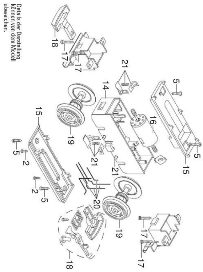
text_image
Technical diagram of a mechanical assembly with numbered components for identificationNote: Several parts are offered unpainted or in another color. Parts that are not listed here can only be repaired by the Märklin repair service department.