10345 - Model making LGB - Free user manual and instructions
Find the device manual for free 10345 LGB in PDF.
| Product type | Automatic reverse loop module for model trains |
| Brand | LGB |
| Model | 10345 |
| Category | Model making (railway network accessory) |
| Power supply | DC current via LGB transformer or power pack |
| Minimum voltage | 10 V DC |
| Maximum current | 3 A (protection beyond) |
| Operating modes | Mode 1 "Basic" (adjustable acceleration, sudden braking); Mode 2 "Prototype-like" (adjustable acceleration and braking) |
| Adjustments | Station stop time (2-60 s or 1-8 min); Acceleration (1-8 s); Braking (mode 2 only) |
| Protection | Against short circuits and overloads >3 A (cutoff 10 s) |
| Dimensions (approx.) | 120 x 80 x 40 mm |
| Weight (approx.) | 100 g |
| Package contents | 1 buffer stop with circuit board, 2 isolation rails with diodes, 1 blue/red track cable, 1 blue/red transformer cable |
| Optional accessories | Additional isolation rails (10153), diodes 1N5400, conductor wires (LGB 50220) |
| Maintenance and cleaning | Clean with a dry cloth; avoid moisture |
| Safety | Observe braking distances; do not use with multi-train system; disconnect before adjustment |
| Compatibility | Analog locomotives; decoder-equipped locomotives possible with analog power supply |
| General information | Manual available in multiple languages (FR, DE, EN, ES, IT, NL); free PDF download |
Frequently Asked Questions - 10345 LGB
User questions about 10345 LGB
0 question about this device. Answer the ones you know or ask your own.
Ask a new question about this device
Download the instructions for your Model making in PDF format for free! Find your manual 10345 - LGB and take your electronic device back in hand. On this page are published all the documents necessary for the use of your device. 10345 by LGB.
USER MANUAL 10345 LGB
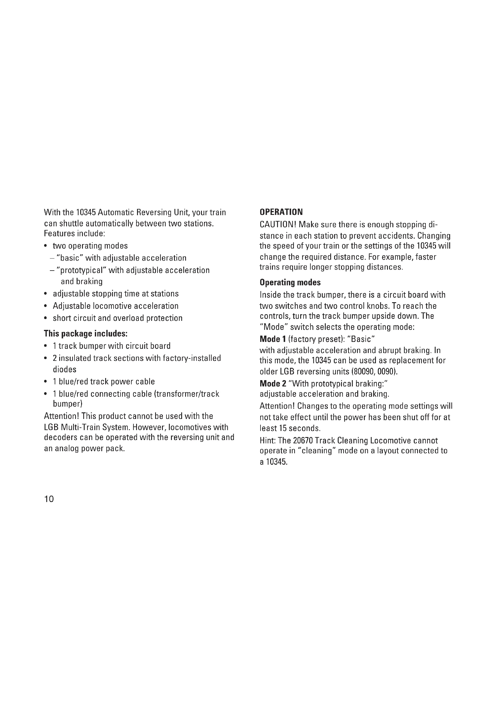
With the 10345 Automatic Reversing Unit, your train can shuttle automatically between two stations. Features include:
- two operating modes
- "basic" with adjustable acceleration
- "prototypical" with adjustable acceleration and braking
adjustable stopping time at stations - Adjustable locomotive acceleration
- short circuit and overload protection
This package includes:
1 track bumper with circuit board
- 2 insulated track sections with factory-installed diodes
- 1 blue/red track power cable
- 1 blue/red connecting cable (transformer/track bumper)
Attention! This product cannot be used with the LGB Multi-Train System. However, locomotives with decoders can be operated with the reversing unit and an analog power pack.
OPERATION
CAUTION! Make sure there is enough stopping distance in each station to prevent accidents. Changing the speed of your train or the settings of the 10345 will change the required distance. For example, faster trains require longer stopping distances.
Operating modes
Inside the track bumper, there is a circuit board with two switches and two control knobs. To reach the controls, turn the track bumper upside down. The "Mode" switch selects the operating mode:
Mode 1 (factory preset): "Basic"
with adjustable acceleration and abrupt braking. In this mode, the 10345 can be used as replacement for older LGB reversing units (80090, 0090).
Mode 2 "With prototypical braking:" adjustable acceleration and braking.
Attention! Changes to the operating mode settings will not take effect until the power has been shut off for at least 15 seconds.
Hint: The 20670 Track Cleaning Locomotive cannot operate in "cleaning" mode on a layout connected to a 10345.
MODE1("BASIC")
Preparation
- Install one of the insulated track sections at the entrance to each station.
- Use the blue/red track power cable to connect the connectors marked "bl" (blue) and "rt" (red) on terminal "A" of the circuit board to the tracks.
- Use the blue/red connecting cable to connect the connectors "bl" (blue) and "rt" (red) on terminal "Power" of the circuit board to the DC output of an LGB throttle or power pack.
- Plug the power supply cord into a house current outlet.
Operation
Place a train on the track between the stations. Adjust the throttle to a medium setting. After a short pause, the train will start and proceed to one station. At the station, it will pass over one of the insulated track sections and stop. After the pre-set waiting time, it will slowly accelerate in the opposite direction and proceed to the other station. The train will shuttle between the stations until the power is switched off.
MODE 2 ("WITH PROTOTYPICAL BRAKING")
Preparation
Hint: To set up this mode, you need two single-strand wires (for example, LGB 50220) to connect the insulated track sections.
- Loosen the screws on the tracks and remove the diodes. Install one of the insulated track sections at the entrance to each station. The interrupted rails of the two insulated track sections must be on opposite sides of the track. The track between the stations must be longer than the train.
- Connect terminals "sw" (black) and "ws" (white) on the circuit board to the insulated track section. Loosen the screws on the insulated track sections and trap the wire between the screw and the rail.
- Use the blue/red track power cable to connect the connectors "bl" (blue) and "rt" (red) of the terminals, respectively, to the tracks.
- Use the blue/red connecting cable to connect the connectors "bl" (blue) and "rt" (red) on terminal "Power" of the circuit board to the DC output of an LGB throttle or power pack.
- Plug the power supply cord into a house current outlet.
Operation
Place a train on the track between the stations. Adjust the throttle to a medium setting. After a short pause, the train will start and proceed to one station. When it crosses the insulated track section, it will slow to a stop. After the preset wait time has elapsed, it will slowly accelerate in the opposite direction and proceed to the other station. The train will shuttle between the stations until the power is switched off.
ADJUSTING PARAMETERS (BOTH MODES)
Adjusting the station stop time
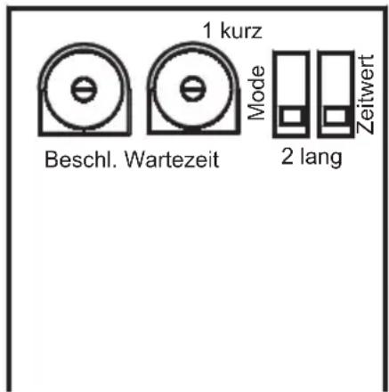
The time for a stop at a station is set by means of the "Pause" switch and the "Wait Time" setting controller on the circuit board.
- Set the range of the time for the stop at the right switch:
"short" short (approximately 2 - 60 seconds)
"long" long (approximately 1 - 8 minutes) - Turn the setting controller to set the time for the stop within these ranges.
- Turn the setting controller to set the acceleration after the stop (1 - 8 seconds).
Adjusting the acceleration and braking
The acceleration and braking are set with the "Delay" adjustment knob on the circuit board. Turn the adjustment knob for faster or slower acceleration and braking. The acceleration and braking cannot be adjusted separately. Hints:
- In mode 1 "Basic", only the acceleration can be adjusted. Braking always is abrupt when the train crosses the insulated track sections.
- New settings for station stop time and acceleration/ braking will take effect after the next station stop. It is not necessary to turn off the power.
Overload Protection
The 10345 is protected against short circuits and overloading. If an overload current of more than 3 amps occurs, the unit will switch off for 10 seconds. However, this overload protection functions only when using a power supply with an output of 3 amps or more. After 10 seconds, the unit will switch on again. When using a power supply with an output of less than 3 amps, a short circuit will trigger the overload protection of your LGB power supply.
Maximum current
The 10345 can be used with trains that draw up to 3 amps. If you are double-headed locos with sound or running long trains with lighted cars, your trains may trigger the overload protection (see Overload Protection).
Minimum Voltage
To operate properly, the 10345 requires an input voltage of 10 volts or more.
1. Emergency stop circuit for Mode 2 "Prototypical"
To prevent your train from hitting the track bumper at the end of the tracks, you can install "emergency stop" circuits at the end of each station. Using two additional insulated track sections (10153, not included), install the diodes (see page 11, Mode 2, paragraph 1). The loco will stop abruptly if it crosses the second insulated track section.
Hint: If the loco continues beyond the diodes, reverse the directions of the diodes.
2. Adjusting braking in mode 1 "Basic"
In mode 1 "Basic," the acceleration controls also control the braking, just as in mode 2 "Prototypical." The braking is activated when the reversing time has elapsed. However, the diodes installed in the insulated track sections usually cause the train to brake abruptly. This can be prevented by carefully adjusting the station stop time to make the braking start before the train reaches the insulated track sections. Adjusting this requires a skilled hand and some patience.
Hints:
Instead of reducing the travel time, you can decrease the speed slightly at the throttle/power pack (and vice versa). This allows a finer adjustment and is effective immediately.
- With this setting, the duration of the stop is short and not adjustable.
3. Adjusting train speed on grades
If you use your 10345 to run a train on a grade, the train will run faster downhill than uphill. However, with a simple electronic circuit, you can reduce the voltage the train receives when going downhill. This circuit works in both modes, Mode 1 "Basic" and Mode 2 "Prototypical":
- Install an additional insulated track section (for example, 10153) between the original insulated track sections.
- Wire a number of diodes (1N5400, not included) in series in the downhill direction. For each diode wired in series, the track voltage will drop by 0.7 - 1 volt.
- Wire a single diode in the uphill direction, parallel to the series of diodes. The train will run at normal speed uphill, but slow on the return trip downhill.
Hint:
In Mode 1 "Basic," you can use a directional "slow section" before the train reaches the station to provide braking in steps.
Mode of operation 2, Prototypical
m = 311 ;
www.maerklin.com/en/imprint.html
255241/0619/Sm5Ef