70503 - Model making LGB - Free user manual and instructions
Find the device manual for free 70503 LGB in PDF.


| Product type | Miniature train set with control console and converter |
| Brand | LGB |
| Model | 70503 |
| Power supply | AC converter (voltage per nameplate) |
| Operating voltage | 0-24 V DC |
| Protection | Built-in overload and short-circuit protection |
| Main functions | Locomotive control, switching of electromagnetic items, lighting |
| Track type | Two-rail direct current (DC) |
| Recommended age | 15 years and up |
| Box contents | Converter, control console, cables, track pieces, locomotive (not explicitly listed) |
| Maintenance | Clean axles with tweezers, dry cloth for the train |
| Safety | Do not use with other converters; connect only to a suitable power outlet; use under parental supervision |
| Warranty | Legal and contractual warranty per enclosed certificate |
| Repairability | LGB after-sales service or specialized retailer |
| Disposal | Recycling via WEEE collection center (crossed-out bin) |
Frequently Asked Questions - 70503 LGB
User questions about 70503 LGB
0 question about this device. Answer the ones you know or ask your own.
Ask a new question about this device
Download the instructions for your Model making in PDF format for free! Find your manual 70503 - LGB and take your electronic device back in hand. On this page are published all the documents necessary for the use of your device. 70503 by LGB.
USER MANUAL 70503 LGB
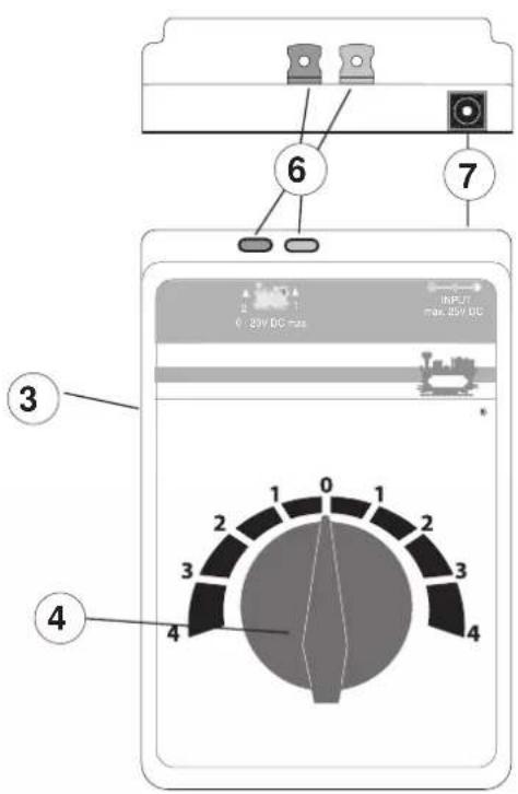
1 - Convertisseur
1 - Power Pack
2 - Connection plug
3 - Train controller
4 - Speed controller
5 - Connection: Control Boxes
6 - Connection: Track
7 - Connection: Power Pack
Liebe Eltern,

7
Fahren
4
Gleis anschließen
Power packs for toys are not suitable to be used as toys. The use of power packs must always be done under the supervision of adults.
■ Make sure you teach your children to use the power pack only in the manner described in the instructions.
Make sure that you teach your children about the dangers of the household current system.
Make sure you inspect the condition of the power pack and its connections to the wall outlet for damage at regular intervals (depending on how often the power pack is used to play with the train), at least once a week. This must be done with the power pack unplugged from the wall outlet. If you have the slightest suspicion that there is damage, the power pack may not be used again until it has been checked and repaired by the LGB Repair Department.1.
1. Safety Notes
Make sure you read the following safety notes before using a LGB power pack for the first time:
- The power pack may only be connected to a wall outlet with voltage that is the same as indicated on the specifications plate on the power pack.
• The power pack is designed for use in a dry area only. - The power pack is not a toy. It is used to supply current to a model railroad layout.
- Never hold the power pack by its power cord when transporting it.
- Check the condition of the power cord regularly and also check the housing for damage. This visual check may be carried out only when the power pack is unplugged from the wall outlet. If you have the slightest suspicion that there is damage, the power pack may not be used again until it has been checked and repaired by an authorized service organization with the appropriate skills (example: LGB Repair Department). In this situation make sure that you dispose of the power pack in the proper manner or send it to the LGB Repair Department for exchange.
- The permanently attached power cord for the power pack may not be changed in any way.2. Connections for the Locomotive Controller and the Track
2.1 Connecting the Locomotive Controller to the Track
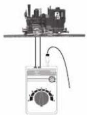
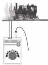
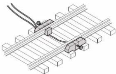
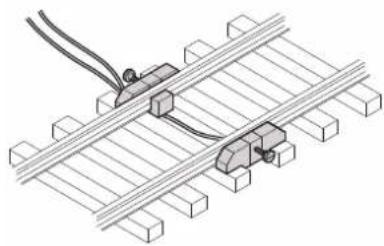
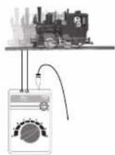
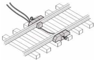
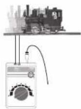
Screw the terminal clips to the track. Connect the red wire and the blue wire to the locomotive controller. (See Figures 1 – 7, Page 8/9)
Important Note:
The train controller may only be connected to the power pack included with the set. The use of other power packs or transformers is not authorized!
2.2 Connecting the Train Controller to the Power Pack
The locomotive controller needs the switched mode power pack for power. Therefore only the switched mode power pack (1) may be plugged with the cable (5) into the socket of locomotive controller (7) – see illustrations on Page 2, Figure 5 on Page 9.
Caution! You must never have two power packs and train controllers connected to the same power circuit (track circuit) at the same time.
2.3 Connections for the Power Pack
The power pack may not be plugged into the wall outlet until the wiring for the layout is finished.
2.4 Technical Data
See the specifications plate on the power pack.
2.5 Setup


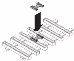
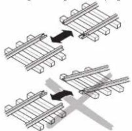
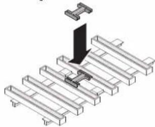
Putting track together Keeping track together
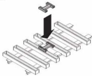
3
Setting up track Connecting track to the locomotive controller and the switched mode power pack
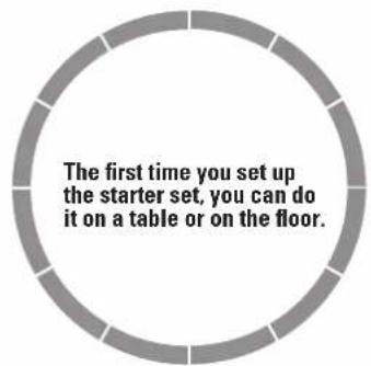
5
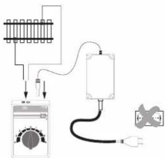
7
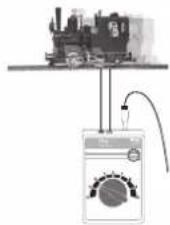
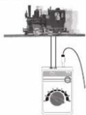
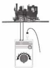
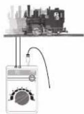
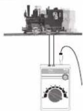
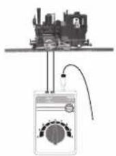
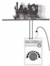
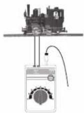
Running the train
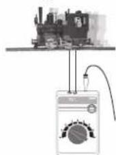
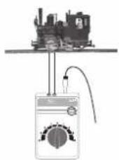
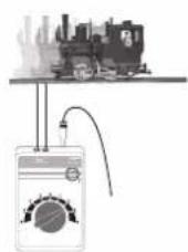
4
Wire connections for track
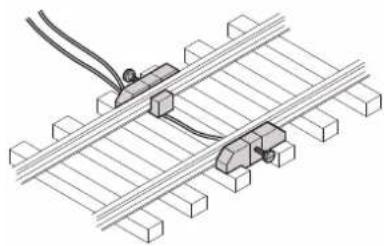
6
Connecting the switched mode power pack to the wall outlet
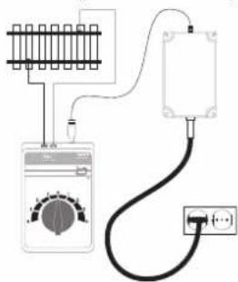
3. Short Circuit or Overload
Overload Protection
A built-in overload protection protects the power pack in the event of an overload or a short circuit. The locomotives will come to a stop, solenoid accessories cannot be controlled, and all lamps/lights connected to the layout will go out.
The following procedure is recommended:
- Unplug the power pack from the wall outlet.
- Look on the layout for the cause of the short circuit and correct it.
- After about 1 minute the overload protection will go back to regular operation.
After this period of time has passed, the power pack can be used again.
If the power pack shuts off again without a short circuit being found, then the power pack is overloaded. In this situation the number of users on the layout (locomotives, solenoid accessories, and lamps/lights) must be reduced.
4. Trouble Running the Train
- If the locomotive does not run, check to make sure that the connections (see setup) are correct or that the wire insulation was pushed into the terminal or that the switched mode power pack is plugged into the power outlet.
- If the locomotive becomes damaged, do not use the locomotive anymore. If car becomes damaged, remove this car from the train and do not use it anymore.
5. Cleaning and Maintenance
- Check to see if hair or dirt gets on the axles on the train and remove this hair or dirt from the axles with the help of a pair or tweezers so that the train runs correctly.
- The train can be wiped with a dry, lint-free cloth.
6. Disposing
Products marked with a trash container with a line through it may not be disposed of at the end of their useful life in the normal household trash. They must be taken to a collection point for the recycling of electrical and electronic devices. There is a symbol on the product, the operating instructions, or the packaging to this effect. The materials in these items can be used again according to this marking. By reusing old devices, materially recycling, or recycling in some other form of old devices such
as these you make an important contribution to the protection of our environment.
Please ask your city, town, community, or county authorities for the location of the appropriate disposal site.
7. Warranty
The warranty card included with this product specifies the warranty conditions.
8. Locomotive
8.1 Safety Notes
- This model may only be used with the operating system designed for it.
- Use only switched mode power supply units and transformers that are designed for your local power system.
- This locomotive must never be supplied with power from more than one power pack.
- Pay close attention to the safety notes in the instructions for your operating system.
• Not for children under the age of 15. - WARNING! Sharp edges and points required for operation.
8.2 Important Notes
- The operating instructions are a component part of the product and must therefore be kept in a safe place as well as included with the product, if the latter is given to someone else.
- Please see your authorized LGB dealer for repairs or spare parts.
- The warranty card included with this product specifies the warranty conditions.
- Disposing: www.maerklin.com/en/imprint.html
8.3 Functions
- This model is designed for operation on LGB two-rail DC systems with conventional LGB DC train controllers or power packs (DC, 0 – 24 volts).
General Note to Avoid Electromagnetic Interference:
A permanent, flawless wheel-rail contact is required in order to guarantee operation for which a model is designed. Do not make any changes to current-conducting parts.
Chers parents,

3
7
Rouler
4
Raccorder la voie
6
3. Court-circuit ou surcharge

Rails vergrendelen
3
7
Rijden
4
Rails aansluiten
6
3. Kortsluiting of overbelasting
Overbelastingbeveiliging
7
Conducir
4
6
3. Cortocircuito o sobrecarga
3
6
- LIEBE ELTERN
- SAFETY NOTES
- 2.1 CONNECTING THE LOCOMOTIVE CONTROLLER TO THE TRACK
- IMPORTANT NOTE
- 2.2 CONNECTING THE TRAIN CONTROLLER TO THE POWER PACK
- 2.3 CONNECTIONS FOR THE POWER PACK
- 2.4 TECHNICAL DATA
- 2.5 SETUP
- SHORT CIRCUIT OR OVERLOAD
- OVERLOAD PROTECTION
- THE FOLLOWING PROCEDURE IS RECOMMENDED
- TROUBLE RUNNING THE TRAIN
- CLEANING AND MAINTENANCE
- DISPOSING
- WARRANTY
- LOCOMOTIVE
- 8.1 SAFETY NOTES
- 8.2 IMPORTANT NOTES
- 8.3 FUNCTIONS
- CHERS PARENTS
- COURT-CIRCUIT OU SURCHARGE
- KORTSLUITING OF OVERBELASTING
- OVERBELASTINGBEVEILIGING
- CORTOCIRCUITO O SOBRECARGA
Brand : LGB
Model : 70503
Category : Model making