22062 - Model making LGB - Free user manual and instructions
Find the device manual for free 22062 LGB in PDF.
| Product Type | Steam electric locomotive (train model) |
| Brand | LGB |
| Model | 22062 |
| Scale | G (1:22.5) |
| Power Supply | Direct current (DC) 0-24 V, compatible with DCC and mfx |
| Decoder | Multiprotocol (DC, DCC, mfx) integrated |
| Factory Address | 03 (DCC); automatic recognition in mfx |
| Sound Functions | Whistle, brake squeal, announcements, compressor noise, fan, sanding, rail joints |
| Lighting | Front/rear lights, tail lights, cabin lighting, shunting lights |
| Pantographs | Electronic control, automatic raising/lowering according to travel direction or manual (function 3) |
| Minimum Curve Radius | R1 (600 mm) possible, recommended R2 (780 mm) and above |
| Maintenance | Lubrication of bearings with Märklin oil (7149); replacement of traction tire (ref. E236 355) |
| Safety Standards | Not suitable for children under 15; contains magnets (swallowing hazard); sharp edges |
| Spare Parts | Traction tire (E236 355); other parts available from LGB retailer |
| Warranty | Statutory and contractual warranty according to attached certificate |
| Dimensions (approx.) | Length: 500 mm, width: 80 mm, height: 120 mm |
| Weight (approx.) | 2.5 kg |
| Number of manual pages | 37 pages |
Frequently Asked Questions - 22062 LGB
User questions about 22062 LGB
0 question about this device. Answer the ones you know or ask your own.
Ask a new question about this device
Download the instructions for your Model making in PDF format for free! Find your manual 22062 - LGB and take your electronic device back in hand. On this page are published all the documents necessary for the use of your device. 22062 by LGB.
USER MANUAL 22062 LGB
natural_image
Green electric locomotive (ECV) with visible tracks, front wheel, and roof-mounted dish (no text or symbols)Modell der RhB Elektrolok Ge 6/6 II
22062
text_image
X! ✓| Table of Contents: | Page |
| Safety Notes 8 | |
| Important Notes 8 | |
| Functions | 8 |
| Information about operation 8 | |
| Multi-Protocol Operation 9 | |
| Service and maintenance 10 | |
| Controllable Functions 10 | |
| Table for CV 11 | |
| Figures | 28 |
| Spare parts 30 |
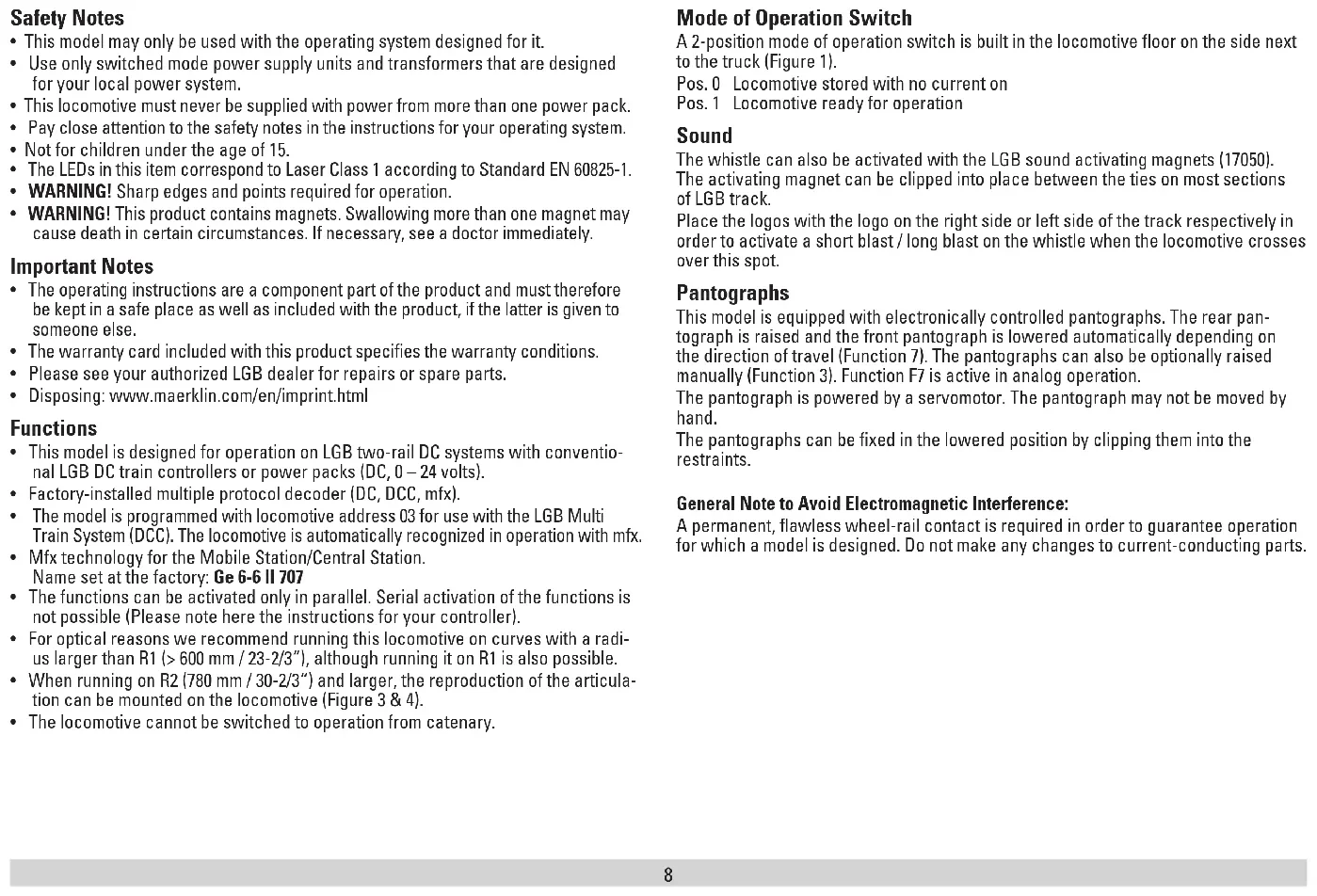
- This model may only be used with the operating system designed for it.
- Use only switched mode power supply units and transformers that are designed for your local power system.
- This locomotive must never be supplied with power from more than one power pack.
- Pay close attention to the safety notes in the instructions for your operating system.
• Not for children under the age of 15.
• The LEDs in this item correspond to Laser Class 1 according to Standard EN 60825-1. - WARNING! Sharp edges and points required for operation.
- WARNING! This product contains magnets. Swallowing more than one magnet may cause death in certain circumstances. If necessary, see a doctor immediately.
Important Notes
- The operating instructions are a component part of the product and must therefore be kept in a safe place as well as included with the product, if the latter is given to someone else.
- The warranty card included with this product specifies the warranty conditions.
- Please see your authorized LGB dealer for repairs or spare parts.
- Disposing: www.maerklin.com/en/imprint.html
Functions
- This model is designed for operation on LGB two-rail DC systems with conventional LGB DC train controllers or power packs (DC, 0 – 24 volts).
• Factory-installed multiple protocol decoder (DC, DCC, mfx). - The model is programmed with locomotive address 03 for use with the LGB Multi Train System (DCC). The locomotive is automatically recognized in operation with mfx.
- Mfx technology for the Mobile Station/Central Station. Name set at the factory: Ge 6-6 II 707
- The functions can be activated only in parallel. Serial activation of the functions is not possible (Please note here the instructions for your controller).
- For optical reasons we recommend running this locomotive on curves with a radius larger than R1 (>600 mm / 23-2/3"), although running it on R1 is also possible.
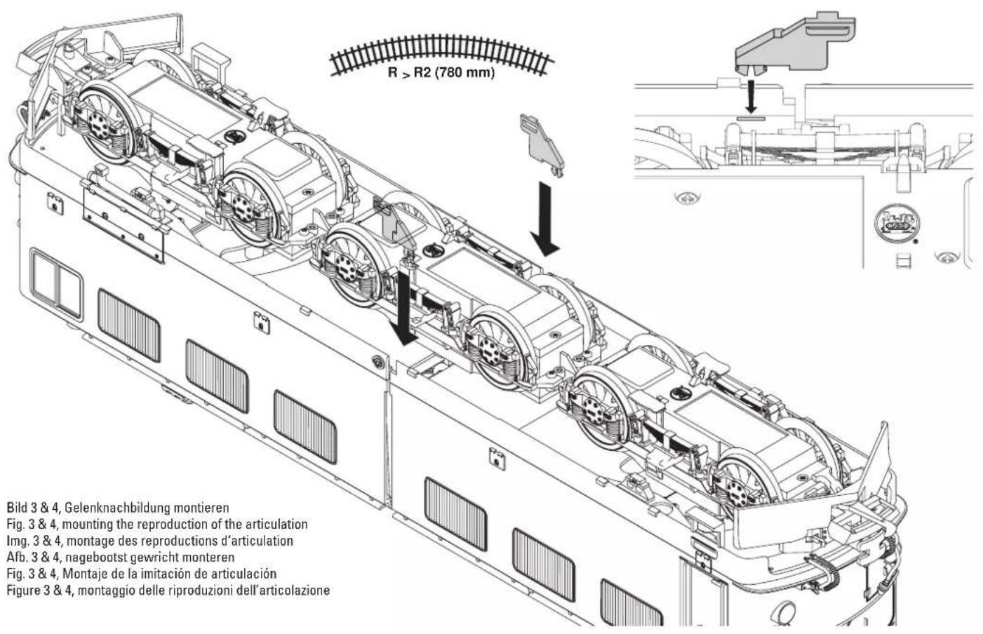
- When running on R2 (780 mm / 30-2/3") and larger, the reproduction of the articulation can be mounted on the locomotive (Figure 3 & 4).
- The locomotive cannot be switched to operation from catenary.
Mode of Operation Switch
A 2-position mode of operation switch is built in the locomotive floor on the side next to the truck (Figure 1).
Pos. 0 Locomotive stored with no current on
Pos. 1 Locomotive ready for operation
Sound
The whistle can also be activated with the LGB sound activating magnets (17050).
The activating magnet can be clipped into place between the ties on most sections of LGB track.
Place the logos with the logo on the right side or left side of the track respectively in order to activate a short blast / long blast on the whistle when the locomotive crosses over this spot.
Pantographs
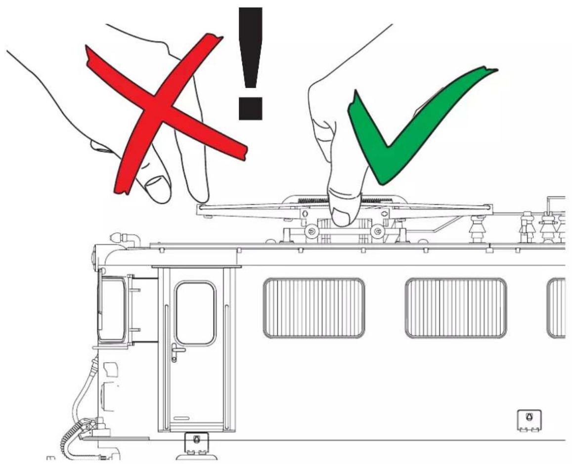
This model is equipped with electronically controlled pantographs. The rear pantograph is raised and the front pantograph is lowered automatically depending on the direction of travel (Function 7). The pantographs can also be optionally raised manually (Function 3). Function F7 is active in analog operation.
The pantograph is powered by a servomotor. The pantograph may not be moved by hand.
The pantographs can be fixed in the lowered position by clipping them into the restraints.
General Note to Avoid Electromagnetic Interference:
A permanent, flawless wheel-rail contact is required in order to guarantee operation for which a model is designed. Do not make any changes to current-conducting parts.
This decoder can also be operated on analog layouts or areas of track that are analog. The decoder recognizes alternating current (DC) and automatically adapts to the analog track voltage. All functions that were set under mfx or DCC for analog operation are active (see Digital Operation).
The built-in sound functions come from the factory inactive for analog operation.
Digital Operation
The decoders are multi-protocol decoders. These decoders can be used under the following digital protocols: mfx or DCC.
The digital protocol with the most possibilities is the highest order digital protocol. The sequence of digital protocols in descending order is:
Priority 1: mfx; Priority 2: DCC; Priority 3: DC
Note: Digital protocols can influence each other. For trouble-free operation, we recommend deactivating those digital protocols not needed by using CV 50. Deactivate unneeded digital protocols at this CV if your controller supports this function.
If two or more digital protocols are recognized in the track, the decoder automatically takes on the highest order digital protocol, example: mfx/DCC; the decoder takes on the mfx digital protocol (see previous table).
Note: Please note that not all functions are possible in all digital protocols. Several settings for functions, which are supposed to be active in analog operation, can be done under mfx and DCC.
Notes on digital operation
- The operating instructions for your central unit will give you exact procedures for setting the different parameters.
- The values set at the factory have been selected for mfx in order to guarantee the best possible running characteristics.
Adjustments may have to be made for other operating systems.
mfx Protocol
Addresses
- No address is required; each decoder is given a one-time, unique identifier (UID).
- The decoder automatically registers itself on a Central Station or a Mobile Station with its UID-identifier.
Programming
- The characteristics can be programmed using the graphic screen on the Central Station or also partially with the Mobile Station.
- All of the Configuration Variables (CV) can be read and programmed repeatedly.
- The programming can be done either on the main track or the programming track.
- The default settings (factory settings) can be produced repeatedly.
- Function mapping: Functions can be assigned to any of the function buttons with the help of the 60212 Central Station (with limitations) and with the 60213/60214/60215 Central Station (See help section in the Central Station).
DCC Protocol
Addresses
- Short address – long address – multiple unit address
- Address range:
1 – 127 for short address and multiple unit address, 1 – 10239 for long address
• Every address can be programmed manually. - Short or long address is selected by means of CV 29 (Bit 5).
- A multiple unit address that is being used deactivates the standard address.
Programming
- The characteristics can be changed repeatedly using the Configuration Variables (CV).
- The CV numbers and the CV values are entered directly.
- The CVs can be read and programmed repeatedly. (Programming is done on the programming track.)
- The CVs can be programmed in any order desired. (PoM - Programming can be done on the main track). PoM is not possible with CVs CV 1, 17, 18, and 29. PoM must be supported by your central controller (Please see the description for this unit.).
- The default settings (factory settings) can be produced repeatedly.
- 14 or 28/126 speed levels can be set.
- All of the functions can be controlled according to the function mapping (see CV description).
• See the CV description for the DCC protocol for additional information.
We recommend that in general programming should be done on the programming track.
SERVICE
Lubrication
The axle bearings should be lubricated occasionally with a small amount of Märklin-Öl (7149).
Changing Traction Tires (E236 355)
- Remove the old traction tire with a small flat blade screwdriver:
- ift the old traction tire out of the groove in the driving wheel.
- Carefully push the new traction tire over the wheel and insert it into the groove of the wheel.
- Check to make sure that the traction tire is properly seated.
| Controllable Functions | ||
| Lighting1 | LV + LR | |
| Sound effect: Long whistle blast 1 Sound 1 | ||
| Sound effect: Squealing brakes off 2 BS | ||
| Raising/lowering pantographs, sequence3 | 3 | Sound 21 +SUSI 15 |
| Sound: Greeting announcement 4 | Sound 4 / 5 | |
| Sound: station announcements, sequence for Chur - St. Moritz 5 Sound 6 | ||
| Sound effect: Operating sounds1,2 | 6 | FS |
| Raising/lowering pantographs, direction-dependent1 | 7 | Sound 22 +SUSI F16 |
| Sound on/off 8 | ||
| ABV, off 9 | ||
| Sound effect: Short whistle blast 10 Sound 2 | ||
| Switching marker lights (1 x white -> 2 x red) 11 | ||
| Engineer's cab lighting 12 AUX 5 & 6 | ||
| Sound effect: Blower | 13 Sound 9 | |
| Sound effect: Compressor | 14 | Sound 11 |
| Sound effect: Sanding | 15 | Sound 15 |
| Sound effect: Announcement | 16 | Sound 16 |
| Sound effect: Announcement | 17 | Sound 17 |
| Sound effect: Announcement | 18 | Sound 18 |
| Double A switching light | 19 | AUX 1 & 2 |
| Marker lights off | 20 | |
| Sound effect: Letting off air | 21 | Sound 14 |
| Sound effect: Rail joints | 22 | Sound 19 |
| Sound effect: Coupling together (buffer to buffer) | 23 | Sound 20 |
^1 active in analog operation
^2 with random sounds
^3 is turned off by Function 7
| Register | Assignment Range Default | ||
| 1 Address 1 – 127 3 | |||
| 2 Minimum speed 0 – 255 8 | |||
| 3 Acceleration delay 0 – 255 4 | |||
| 4 Braking delay 0 – 255 4 | |||
| 5 Maximum speed 0 – 255 195 | |||
| 8 Reset 8 159 | |||
| 13 Function F1 – F8 with alternative track signal 0 – 255 96 | |||
| 14 Function FL, F9 – F15 with alternative track signal 0 – 255 1 | |||
| 17 Expanded address, higher value byte | 192 – 231 | 192 | |
| 18 Expanded address, lower value byte | 0 – 255 128 | ||
| 19 Multiple unit operation address | 0 – 255 0 | ||
| 21 Functions F1 – F8 with multiple unit operation | 0 – 255 0 | ||
| 22 Function FL, F9 – F15 with multiple unit operation | 0 – 255 0 | ||
| 27 | Bit 4: Braking mode voltage against the direction of travel | 0/16 | 16 |
| Bit 5: Braking mode voltage with the direction of travel | 0/32 | ||
| 29 | Bit 0: Direction normal/inverted | 0/1 | 6 |
| Bit 1: Number of speed levels 14/28(128) | 0/2 | ||
| Bit 2: Analog operation off/on | 0/4 | ||
| Bit 5: short / long address active | 0/32 | ||
| 50 | Alternative Formats' | ||
| Bit 0: Analog AC | 0/1 | 15 | |
| Bit 1: Analog DC | 0/2 | ||
| Bit 2: MM | 0/4 | ||
| Bit 3: mfx off/on | 0/8 | ||
| 60 | Multi-station announcement | ||
| Bit 0 – 3: Number of stations | 0 – 15 | 46 | |
| Bit 4: Last announcement changes the sequence | 0/16 | ||
| Bit 5: Locomotive direction changes the sequence | 0/32 | ||
| Bit 6: Start for the sequence | 0/64 | ||
| 63 Total volume | 0 – 255 255 | ||
| Register | Assignment Range Default | ||
| 64 | Threshold for squealing brakes | 0 – 255 15 | |
| 67 – 94 | Speed table for speed levels 1 – 28 | 0 – 255 | |
| 112 | Mapping lights in the front, mode | 0 – 21 | 1 |
| 113 | Mapping lights in the front, dimmer | 0 – 255 255 | |
| 114 | Mapping lights in the front, cycle | 0 – 255 20 | |
| 176 | Minimum speed in analog DC | 1 – 255 50 | |
| 177 | Maximum speed in analog DC | 1 – 255 129 |
Note:
At www.LGB.de you will find a tool you can use to calculate different decoder settings as well an extensive description of the decoder and the settings. Programming the decoder settings with the 55015 Universal Hand Controller is also explained in these instructions.
natural_image
Technical line drawing of a mechanical assembly with no visible text or symbols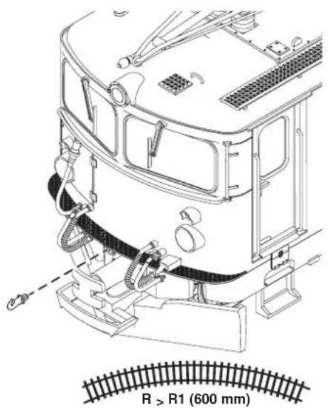
text_image
R > R1 (600 mm)Bild 1, Betriebsartenschalter
Fig. 1, Power control switch
Img. 1, Modes d'exploitation
Afb. 1, Bedrijfssoorten schakelaar
Fig. 1, Selector de modo de funcionamiento
Figure 1, Commutatore del tipo di esercizio
Bild 2, Zughaken
Fig. 2, tow hook
Img. 2, crochet de remorquage
Afb. 2, trekhaak
Fig. 2, gancho de remolque
Figure 2, gancio di traino
text_image
R > R2 (780 mm) Bild 3 & 4, Gelenknachbildung montieren Fig. 3 & 4, mounting the reproduction of the articulation Img. 3 & 4, montage des reproductions d'articulation Afb. 3 & 4, nagebootst gewricht monteren Fig. 3 & 4, Montaje de la imitación de articulación Figure 3 & 4, montaggio delle riproduzioni dell'articolazione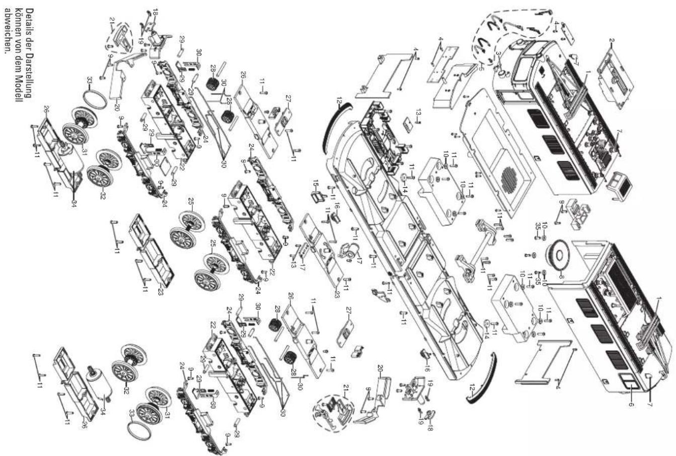
The following listing gives the factory settings in the area of function mapping for the decoder to 20580. These settings can be changed multiple times and at any time. See also supplemental decoder instructions.
Note: The settings for function mapping are very complex and require extensive knowledge of working with DCC.