
PD-8 ECO COM1 - Motion detector STEINEL - Free user manual and instructions
Find the device manual for free PD-8 ECO COM1 STEINEL in PDF.
User questions about PD-8 ECO COM1 STEINEL
0 question about this device. Answer the ones you know or ask your own.
Ask a new question about this device
Download the instructions for your Motion detector in PDF format for free! Find your manual PD-8 ECO COM1 - STEINEL and take your electronic device back in hand. On this page are published all the documents necessary for the use of your device. PD-8 ECO COM1 by STEINEL.
USER MANUAL PD-8 ECO COM1 STEINEL
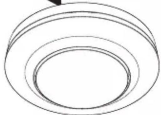
natural_image
White 3D-rendered ceiling-mounted device with a hexagonal grille and circular top (no text or symbols visible)
natural_image
3D rendering of a white cylindrical mechanical component with a central dome and flange (no text or symbols visible)DE
Inhalt
natural_image
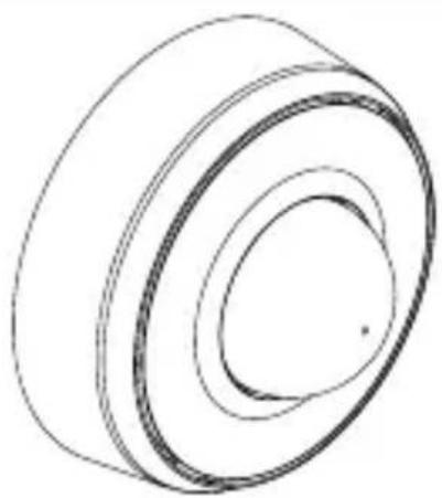
Technical line drawing of two mechanical components with concentric rings and radial grooves (no text or symbols)1 × 1 ×

1×

natural_image
Technical line drawing of two mechanical components with concentric rings and a meshed base (no text or symbols)1 × 1 ×

1×
natural_image
Technical line drawing of a mechanical component with a 70 mm dimension label (no text or symbols beyond the dimension)natural_image
Technical line drawing of a mechanical component with concentric rings and mounting brackets (no text or symbols)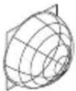
1 × 1 ×

1×

natural_image
Pure technical line drawing of a cylindrical mechanical part with concentric rings (no text or symbols)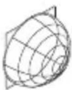
1 × 1 ×

1×

max. 10 Sensoren
max. 10 Sensoren
5. Montage

natural_image
Diagram of a computer motherboard with an open lid and cable, showing internal components and wiring (no text or labels)natural_image
Technical diagram of a mechanical assembly with screw fasteners and a rotating shaft (no text or symbols)natural_image
Diagram of a mechanical component with arrows indicating direction (no text or symbols)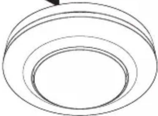
natural_image
Simple line drawing of concentric circular rings (no text or symbols)
natural_image
Simple black-and-white icon of a U-shaped magnet with two side blocks and two lightning bolts below (no text or symbols)natural_image
Technical diagram of a mechanical device with a pencil and directional arrows indicating assembly or operation (no text or symbols present)

- About this document 39
- General safety precautions 39
- System description 40
- Electrical connection 51
- Installation 55
- Function 63
- Maintenance and care 67
- Disposal 67
- Manufacturer's warranty 68
- Technical specifications 71
- Troubleshooting 72
1. About this document
- Under copyright. Reproduction either in whole or in part only with our consent.
- Subject to change in the interest of technical progress.

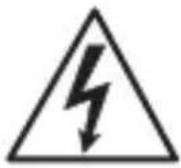
Hazard warning!

Warning of hazards from electricity!

Warning of hazards from water!
2. General safety precautions

Failure to observe these operating instructions presents hazards!
These instructions contain important information on the safe use of this product. Particular attention is drawn to potential hazards. Failure to observe this information may lead to death or serious injuries.
- Read instructions carefully.
- Follow safety advice.
-
Keep instructions within easy reach.
-
Working with electrical current may produce hazardous situations. Touching live parts can result in electrical shock, burns or death.
- Work on mains voltage must only be performed by qualified, skilled personnel.
- National wiring regulations and electrical operating conditions must be observed (e.g. D: VDE 0100, A: ÖVE-ÖNORM E8001-1, CH: SEV 1000).
- Only use genuine replacement parts.
– Repairs must only be carried out by companies qualified to do so.
3. System description
Proper use
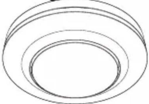
- Sensor.
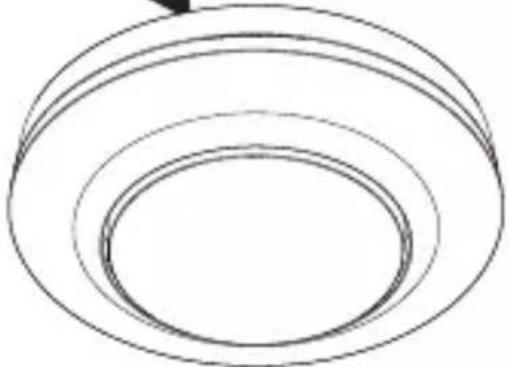
- For ceiling mounting indoors.
- AP version for surface-mounted installation.
- UP version for concealed installation.
– DE version for recessed ceiling mounting.
Sensor variables
The sensor can detect the following sensor variables:
- Movement (MD & PD).
– Human presence (PD).
– Light level (MD & PD).
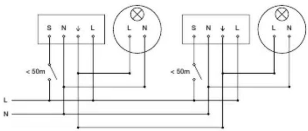
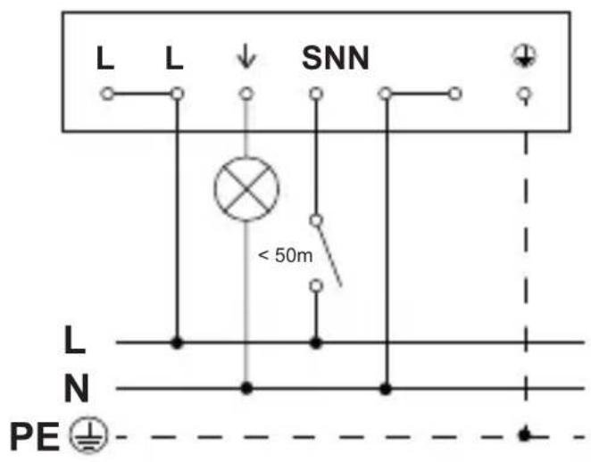
Cable length between sensor and button < 50 m.
Operating principle
The human presence detector and motion detector are equipped with pyro sensors. The pyro sensors detect the invisible heat emitted by moving objects (e.g. people, animals etc.).
The human presence detector features an additional presence detection capability that provides greater sensitivity for detecting smaller-type movements too. The heat detected in this way is converted electronically into a signal that triggers the relay. Heat is not detected through obstacles (such as walls or panes of glass).
Interface
COM1: relay 1
The COM1 relay switches loads. Signals are processed and sent out.
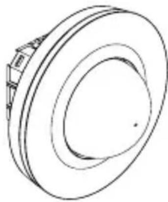
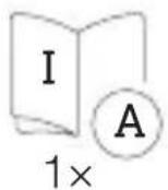
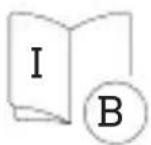
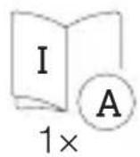
Package contents, MD / PD-8 ECO COM1, concealed installation
3.1
natural_image
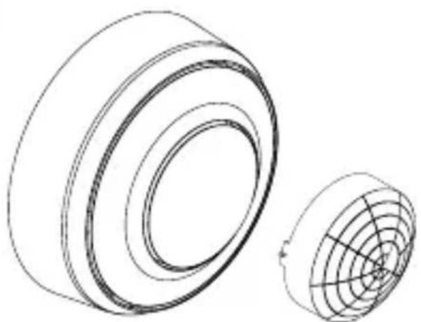
Technical line drawing of two mechanical components with concentric rings and radial grooves, labeled '1×1×' below (no text or symbols on the diagram itself)
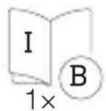
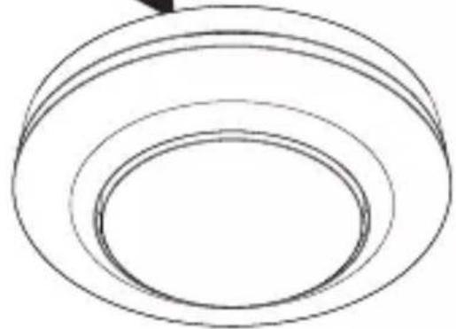
- 1 Sensor
- 1 shroud
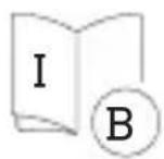
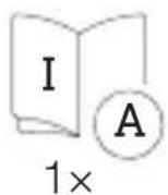
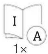
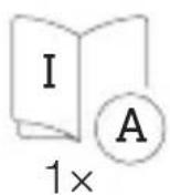
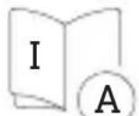
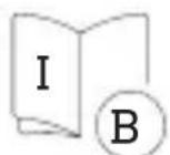
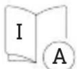
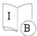
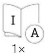
- 1 safety data sheet (A)
- 1 Quick start guide (B)
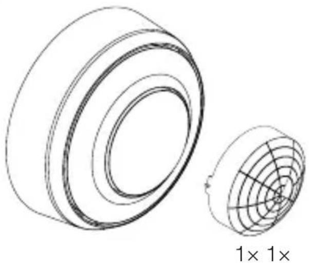
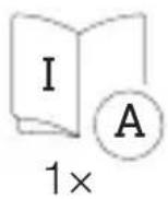
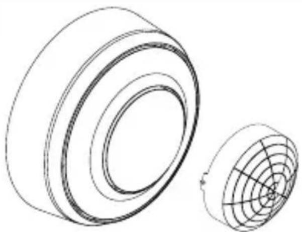
Package contents, MD / PD-8 ECO COM1, surface-mounted installation
3.2
natural_image
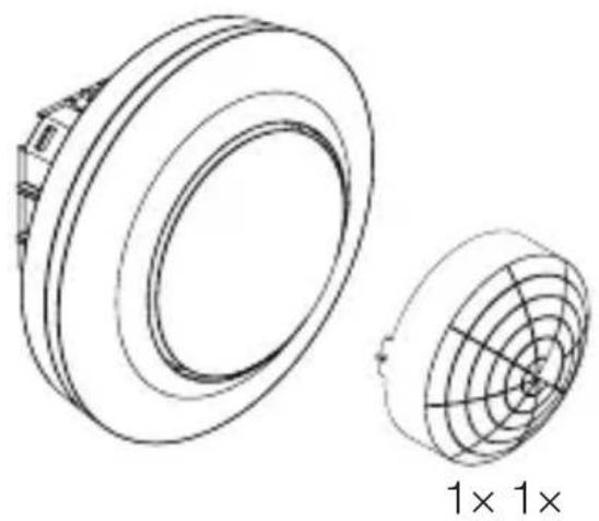
Technical line drawing of two cylindrical components with internal grid patterns, labeled '1× 1×' (no text or symbols on the diagram itself)

- 1 Sensor
- 1 shroud
- 1 safety data sheet (A)
- 1 Quick start guide (B)
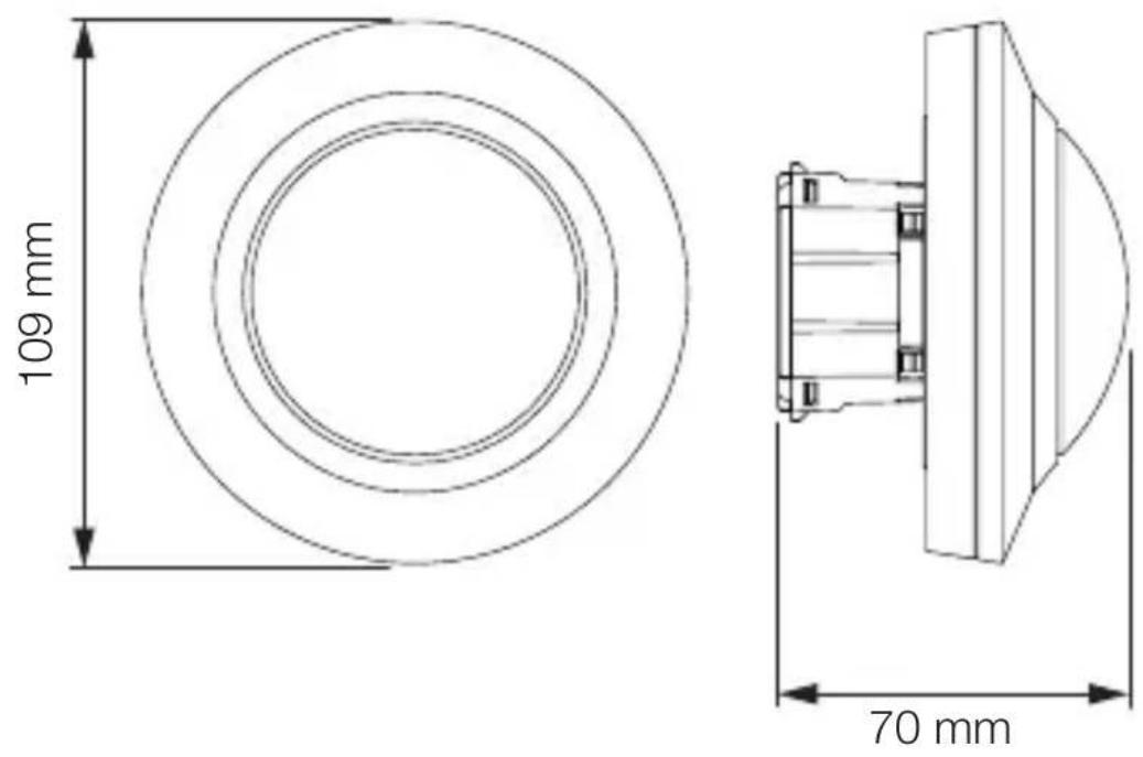
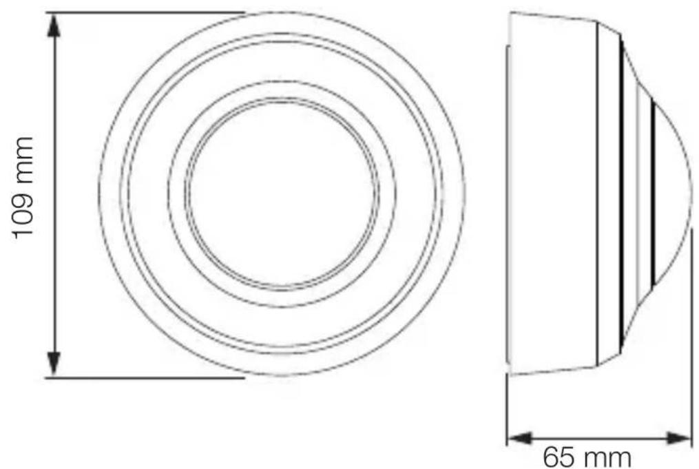
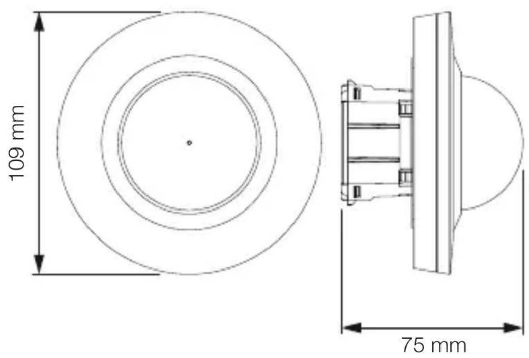
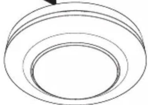
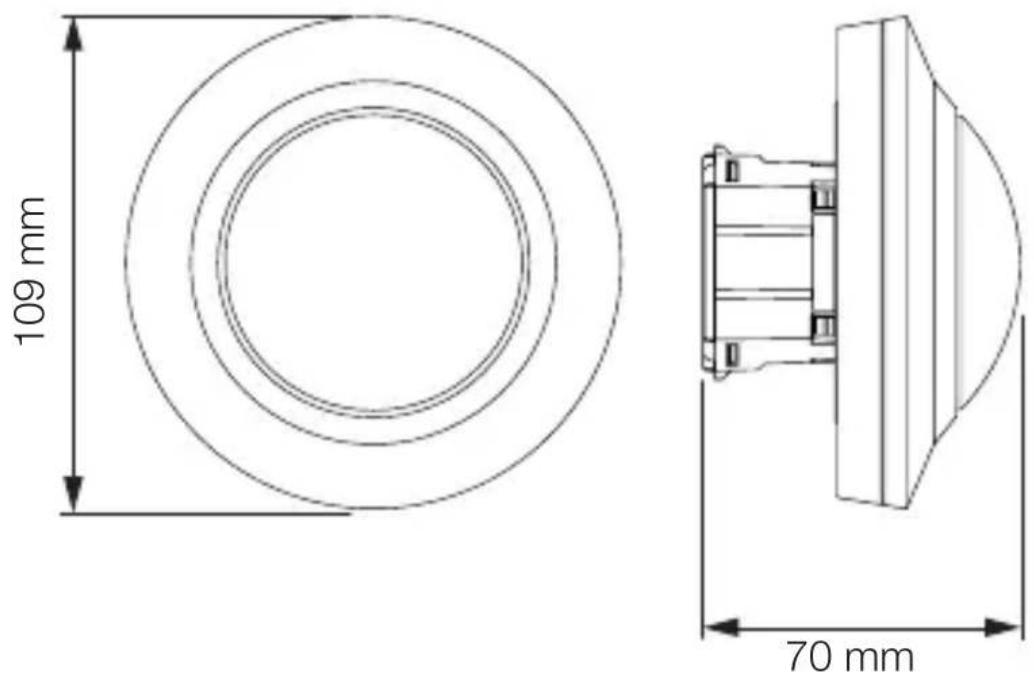
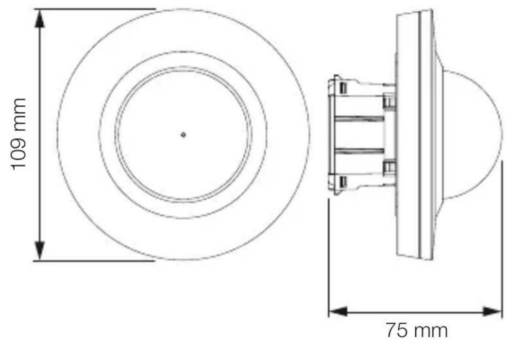
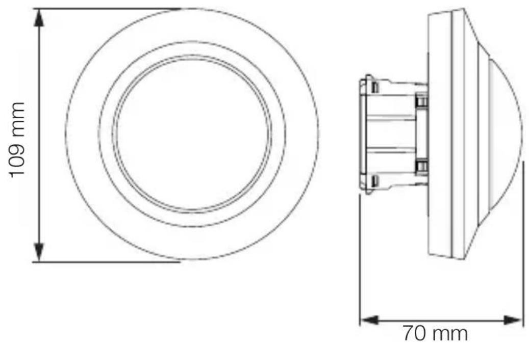
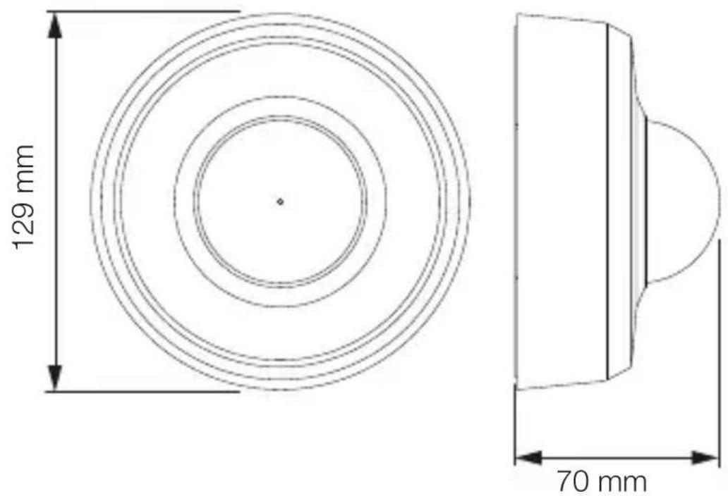
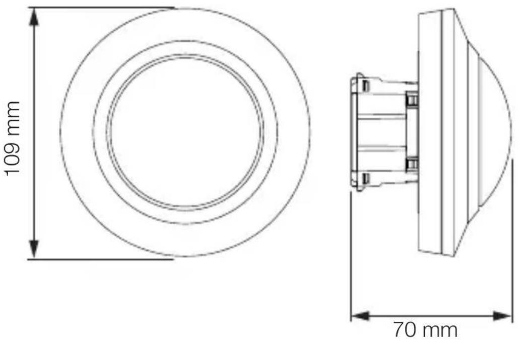
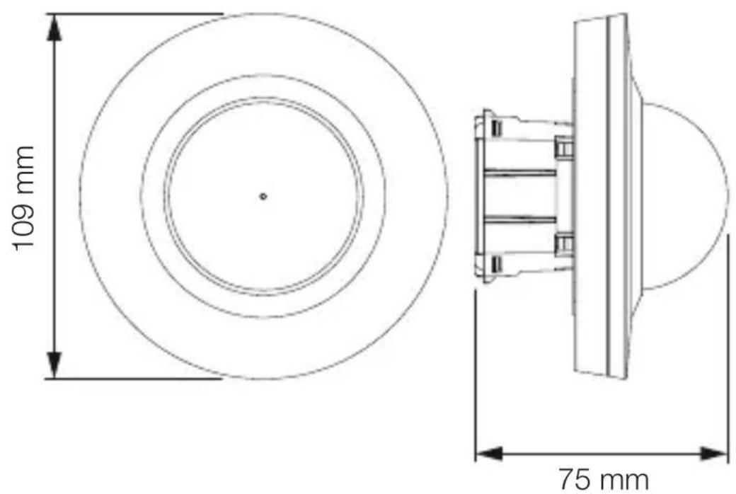
Product dimensions, MD / PD-8 ECO COM1, concealed installation
3.3
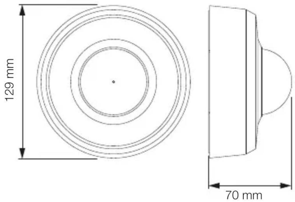
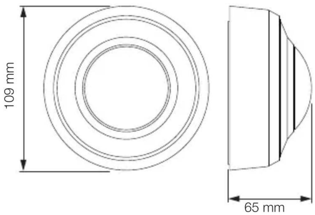
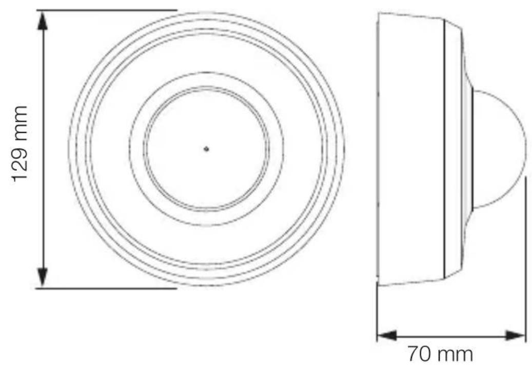
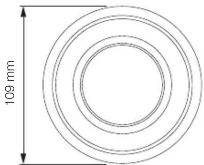
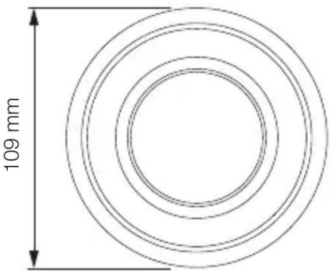
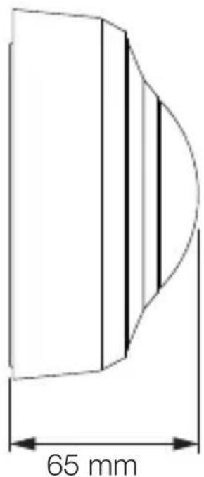
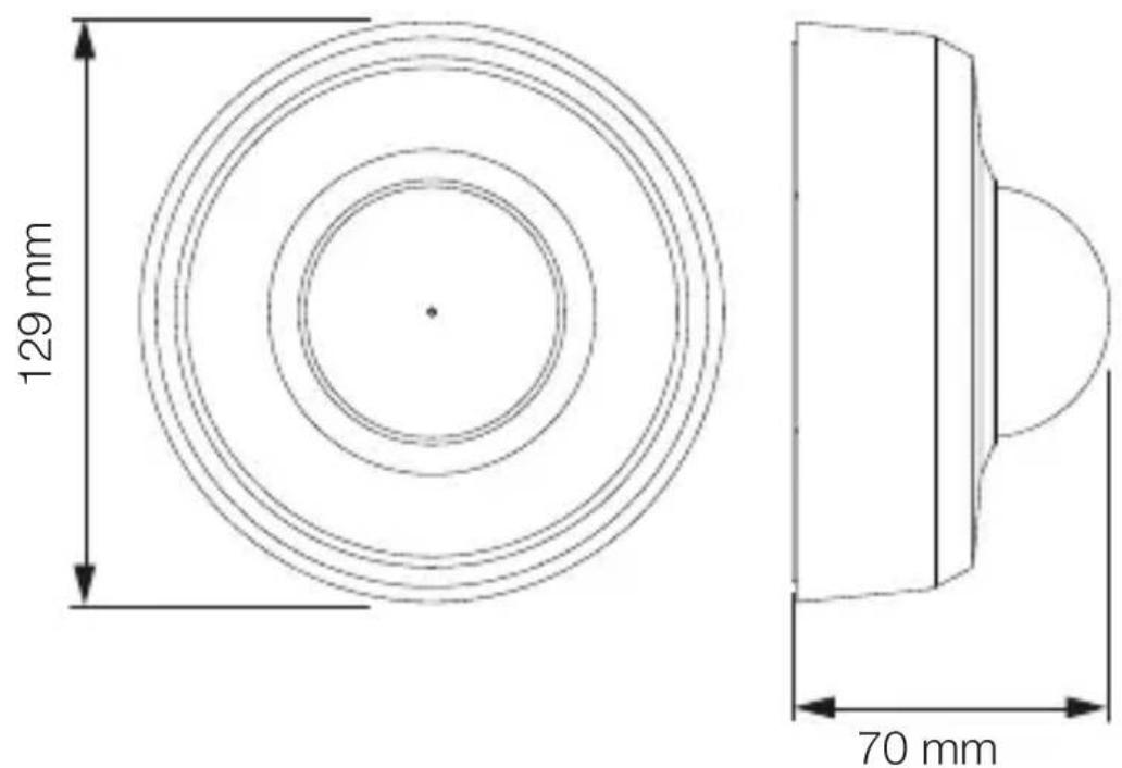
Product dimensions, MD / PD-8 ECO COM1, surface-mounted installation
3.4
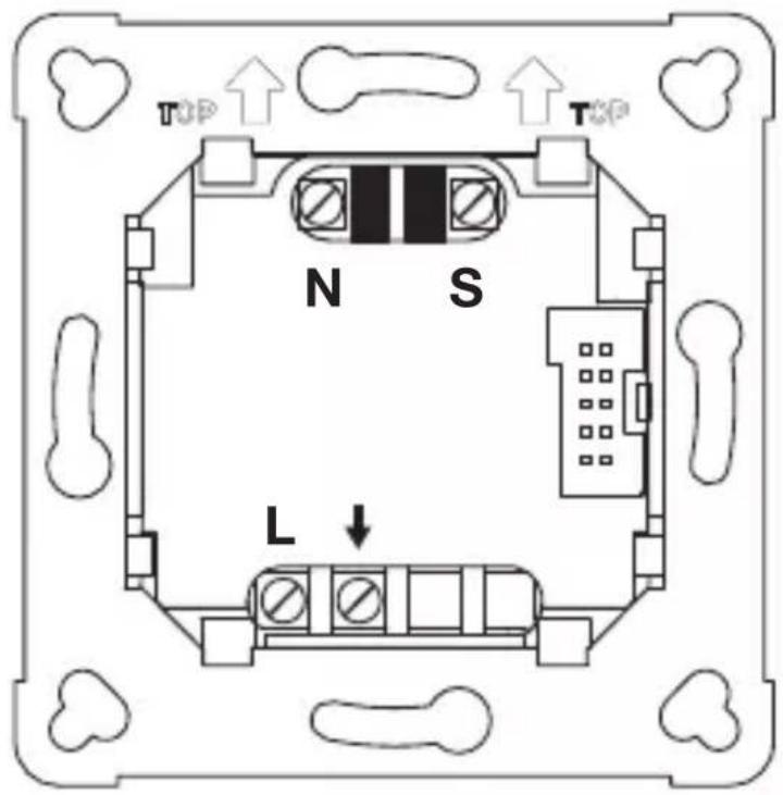
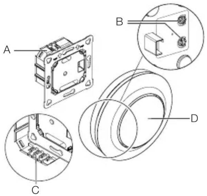
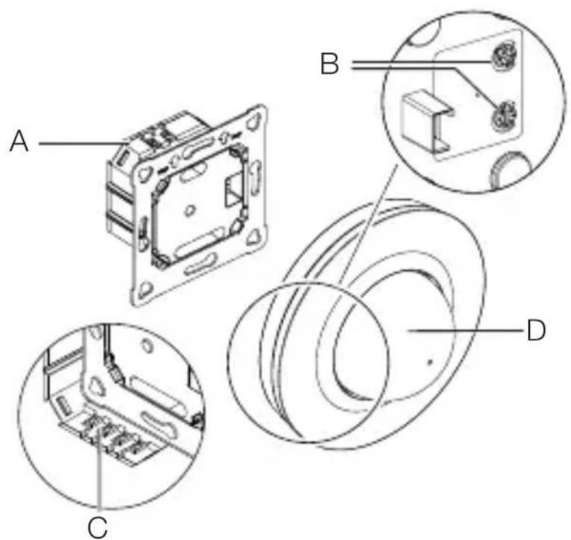
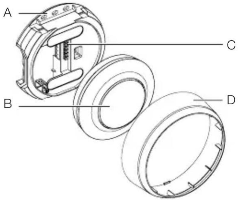
Product components, MD / PD-8 ECO COM1, concealed installation
GB
3.5
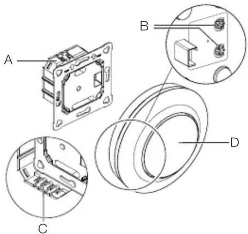
A Load module
B Potentiometer pin
C Connecting terminal
D Sensor module
Product components, MD / PD-8 ECO COM1, surface-mounted installation
3.6

A Surface-mounting adapter
B Sensor module
C Connecting terminal
D Cover ring
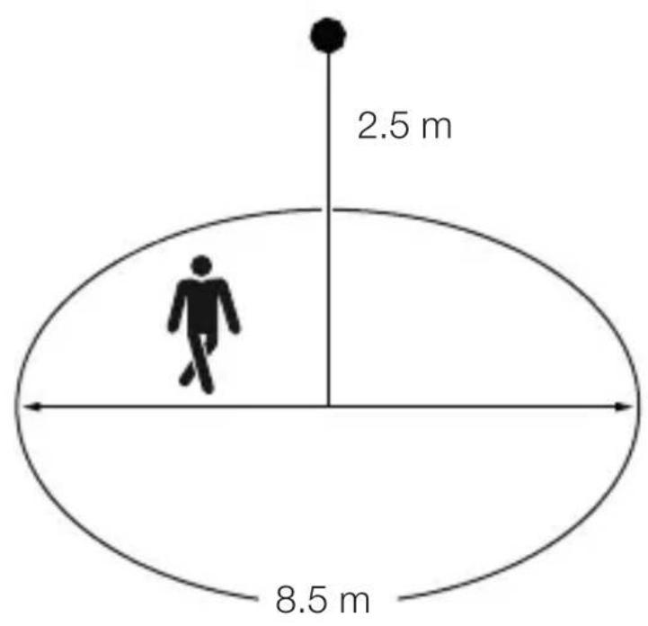
Detection zone, MD-8 ECO COM1
GB
3.7
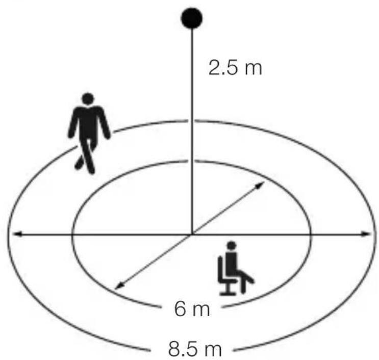
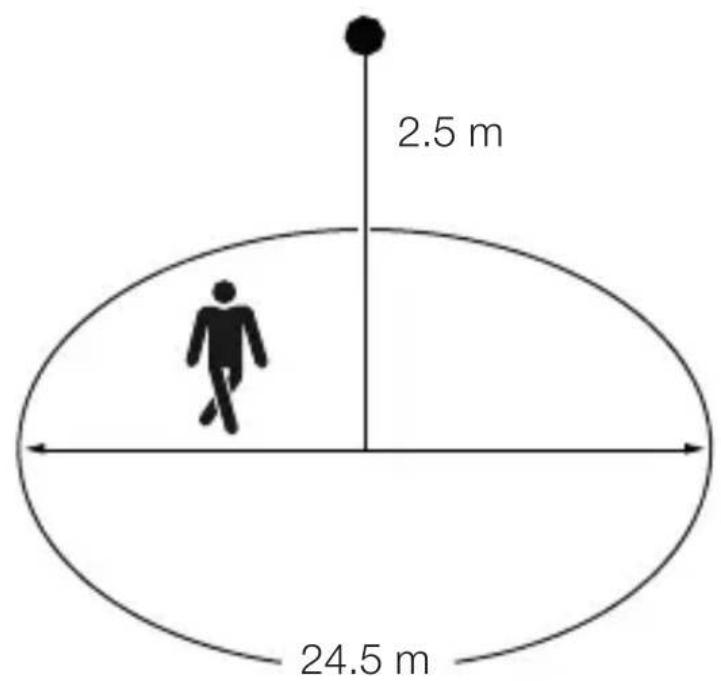
Detection zone, PD-8 ECO COM1
3.8
Package contents, MD / PD-24 ECO COM1, concealed installation
3.9
natural_image
Technical line drawing of a mechanical component with concentric rings and mounting brackets (no text or symbols)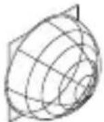
1 × 1 ×
1×
- 1 Sensor
- 1 shroud
- 1 safety data sheet (A)
- 1 Quick start guide (B)
Package contents, MD / PD-24 ECO COM1, surface-mounted installation
3.10

natural_image
Pure 3D diagram of concentric circular layers without any text, numbers, or symbols
1 × 1 ×
1×
- 1 Sensor
-1 shroud - 1 safety data sheet (A)
- 1 Quick start guide (B)
Product dimensions, MD / PD-24 ECO COM1, concealed installation
GB
3.11
Product dimensions, MD / PD-24 ECO COM1, surface-mounted installation
3.12
Product components, MD / PD-24 ECO COM1, concealed installation
3.13

A Load module
B Potentiometer pin
C Connecting terminal
D Sensor module
Product components, MD / PD-24 ECO COM1, surface-mounted installation
GB
3.14

A Surface-mounting adapter
B Sensor module
C Connecting terminal
D Cover ring
Detection zone, MD-24 ECO COM1
3.15
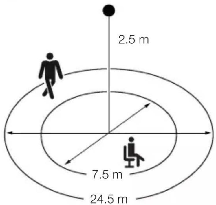
Detection zone, PD-24 ECO COM1
3.16
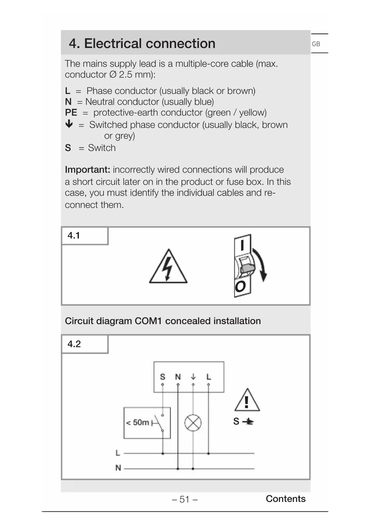
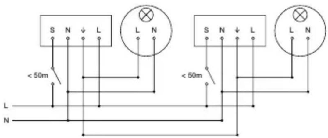
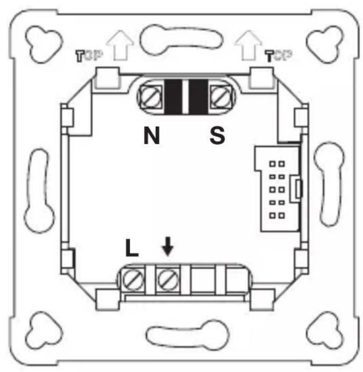
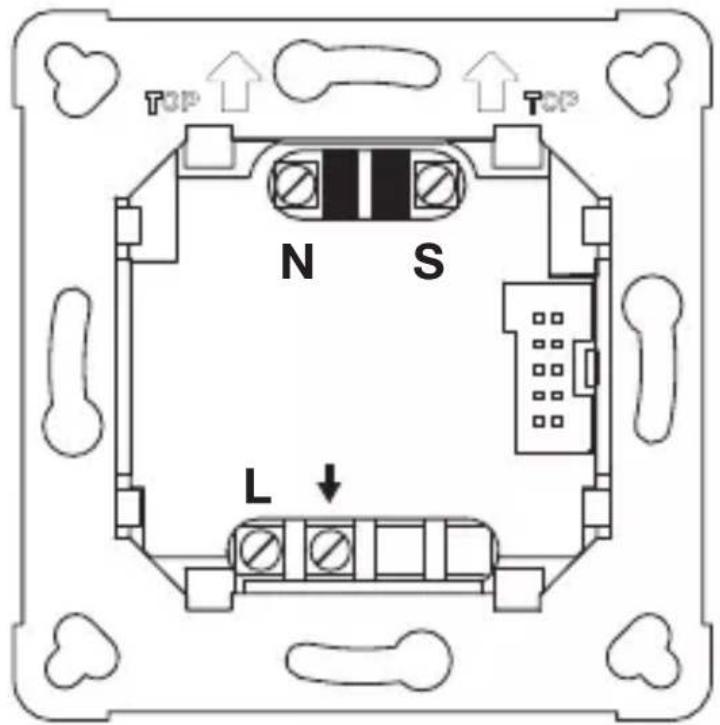
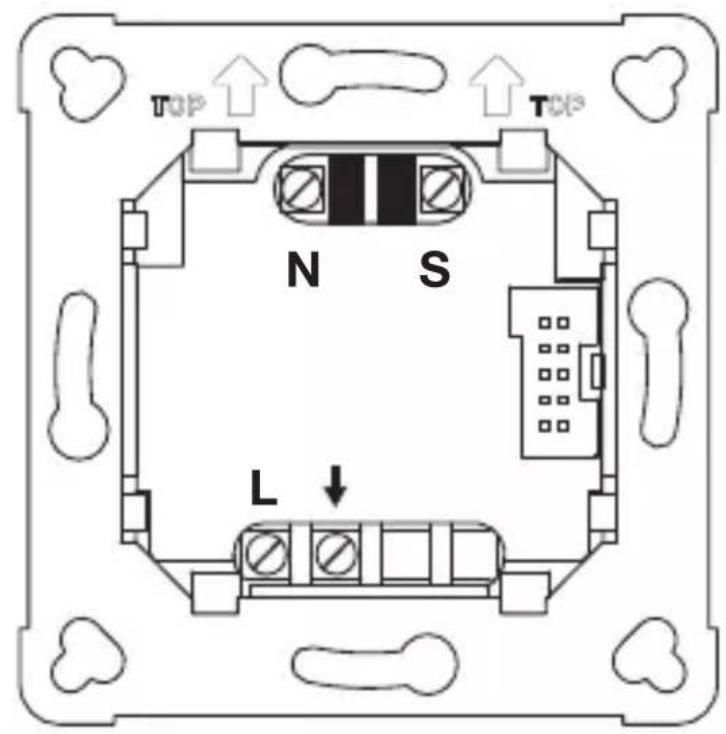
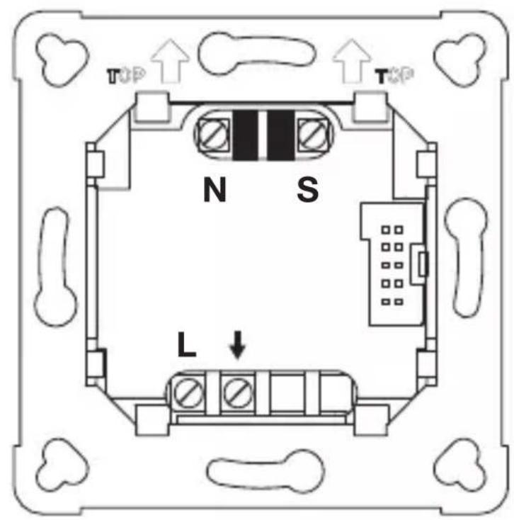
4. Electrical connection
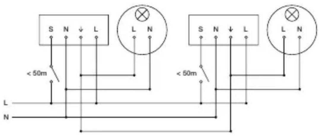
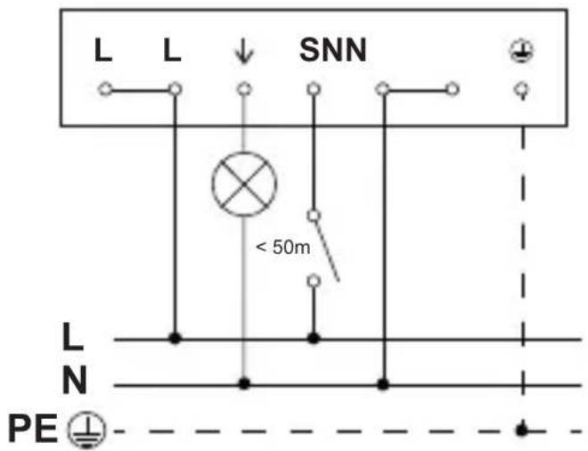
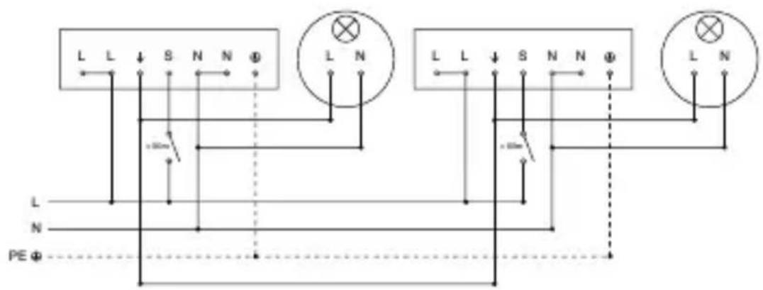
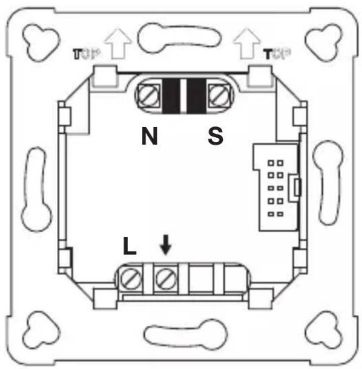
The mains supply lead is a multiple-core cable (max. conductor ∅ 2.5 mm):
L = Phase conductor (usually black or brown)
N = Neutral conductor (usually blue)
PE = protective-earth conductor (green / yellow)
↓ = Switched phase conductor (usually black, brown or grey)
S = Switch
Important: incorrectly wired connections will produce a short circuit later on in the product or fuse box. In this case, you must identify the individual cables and reconnect them.
4.1
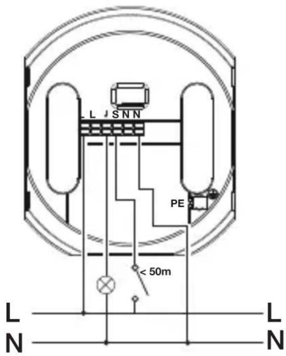
Circuit diagram COM1 concealed installation
4.2
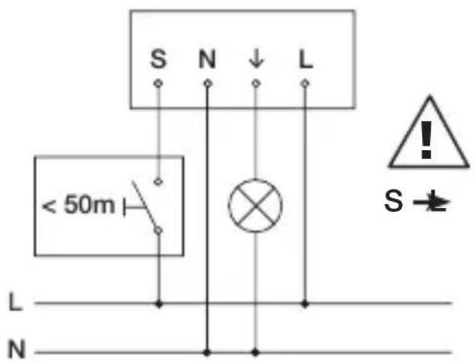
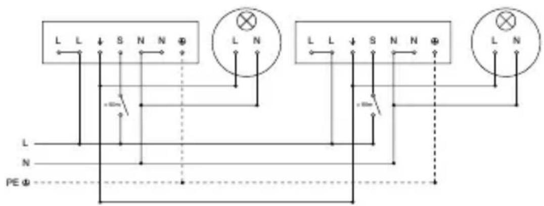
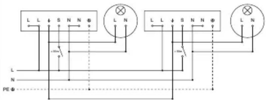
Circuit diagram COM1 concealed installation – parallel connection
4.3

10 sensors max.
Connecting mains power supply lead COM1, concealed installation
4.4
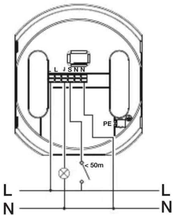
Circuit diagram COM1 surface-mounted installation
GB
4.5

Circuit diagram COM1 surface-mounted installation-parallel connection
4.6

10 sensors max.
Connecting mains power supply lead COM1, surface-mounted installation
4.7
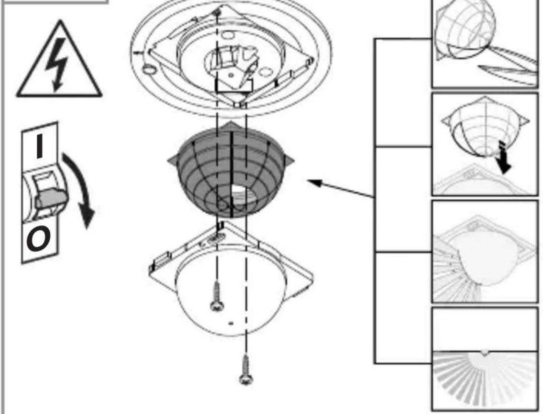
5. Installation

Hazard from electrical power.
Touching live parts can result in electrical shock, burns or death.
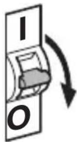
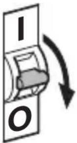
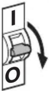
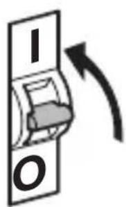
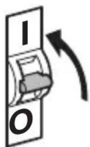
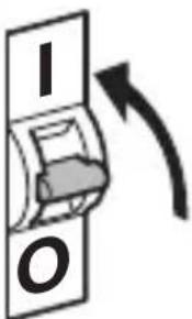
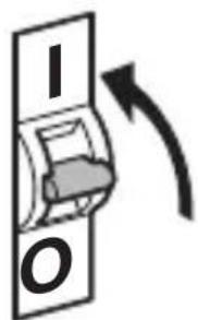
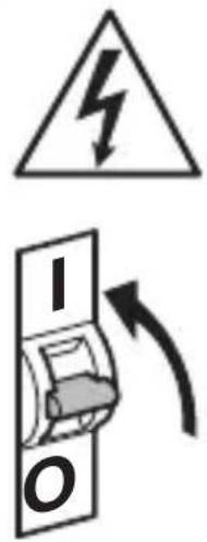
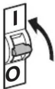
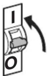
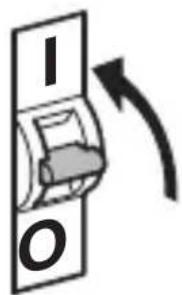
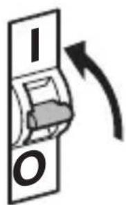
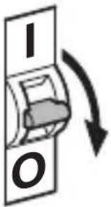
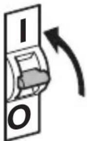
- Switch OFF power and interrupt power supply.
- Using a voltage tester, check to make sure that the power supply is disconnected.
- Make sure power supply remains interrupted.
Risk of damage to property!
Mixing up connection leads may produce a short circuit.
• Identify connection leads.
- Connect the leads correctly.
Preparing for installation
- Check all components for damage. Do not use the product if it is damaged.
- Select an appropriate site to install the product.
-Take reach into consideration.
-Take reach and motion detection into consideration.
-Vibration-free.
-No obstacles in detection zone.
-Not in explosive atmospheres.
-Not on normally flammable surfaces.
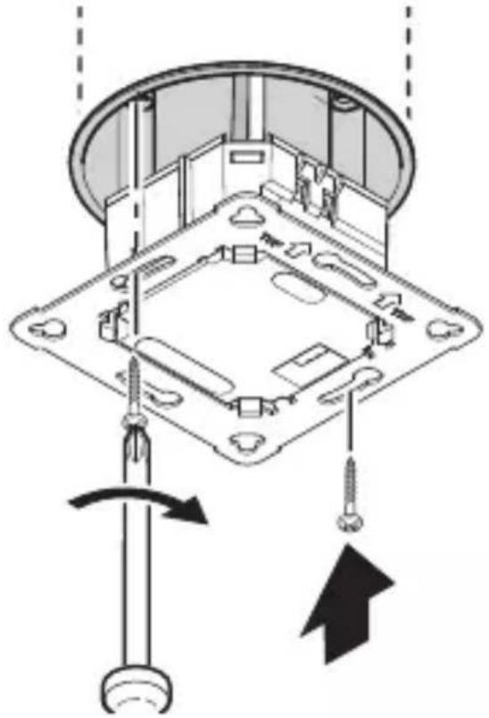
Mounting procedure, concealed installation
5.1
natural_image
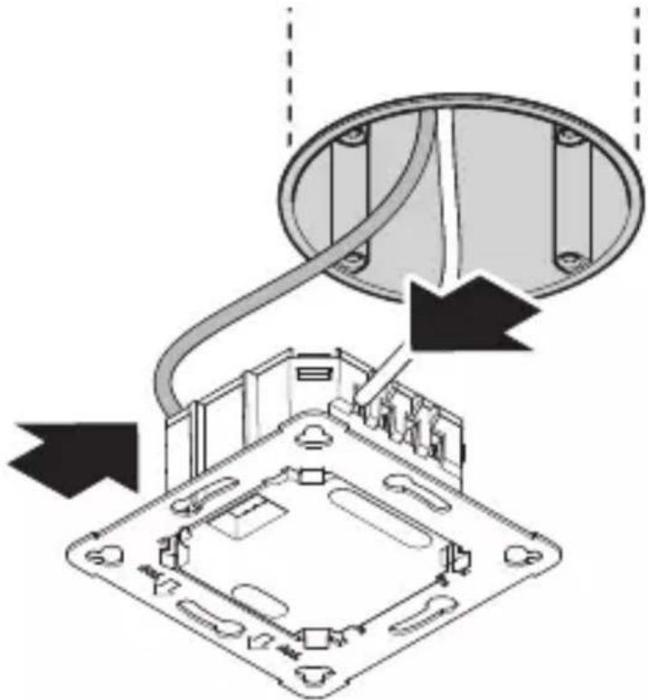
Diagram of a computer motherboard with an open lid and cable, showing internal components and wiring (no text or labels)- Check to make sure the power supply is switched OFF.
- Connect to mains power supply.
→"4. Electrical connection"
5.2
natural_image
Technical diagram of a mechanical assembly with screw fasteners and a rotating shaft (no text or symbols)- Firmly screw load module onto mounting box.
5.3


natural_image
Diagram of a mechanical component with arrows indicating direction (no text or symbols)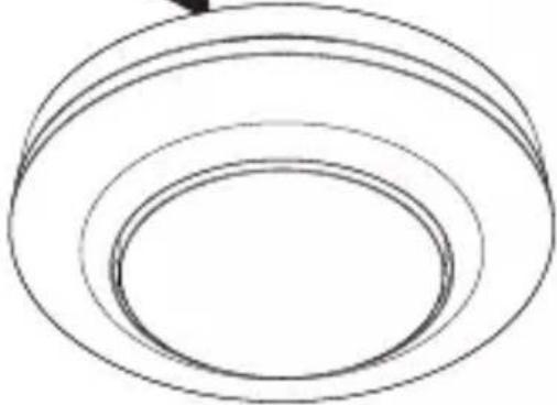
natural_image
Simple line drawing of concentric circular rings (no text or symbols)
natural_image
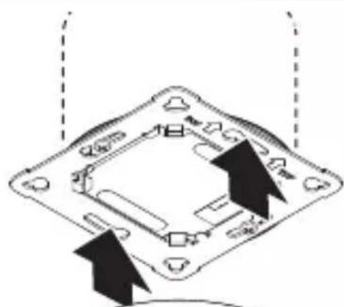
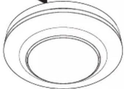
Simple black-and-white diagram of a U-shaped magnet with two side blocks and two directional arrows below (no text or symbols)- Fit magnetic sensor module on load module.
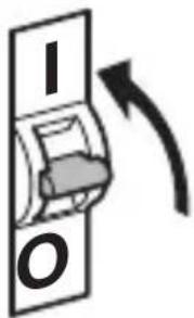
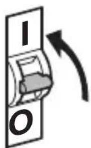
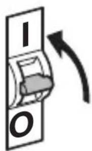
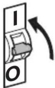
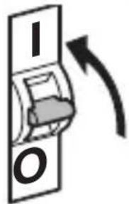
- Switch ON power supply.
Mounting procedure, surface-mounted installation
5.4

natural_image
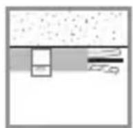
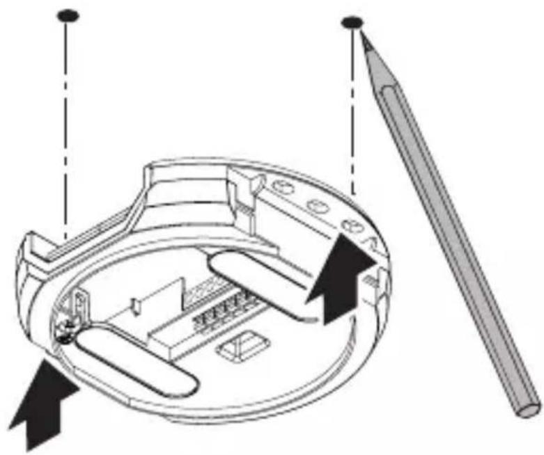
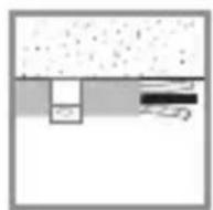
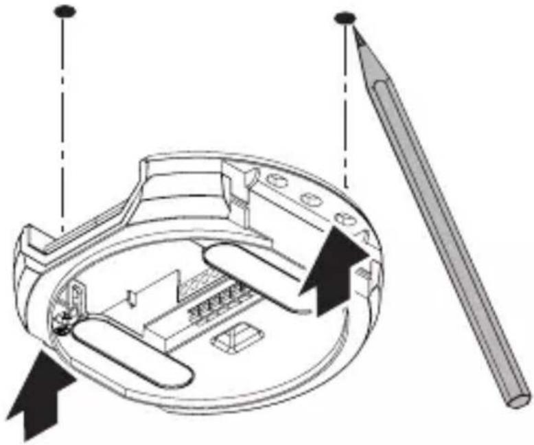
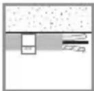
Technical diagram of a mechanical device with internal components and directional arrows, no visible text or symbols- Check to make sure the power supply is switched OFF.
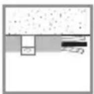
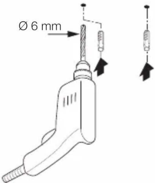
- Mark drill holes.
5.5


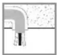
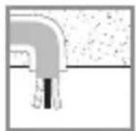
- Drill holes (∅ 6 mm) and fit wall plugs.
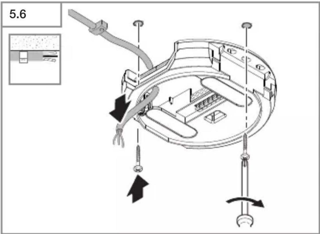
GB
- Feed through cable.
- Screw on load module.
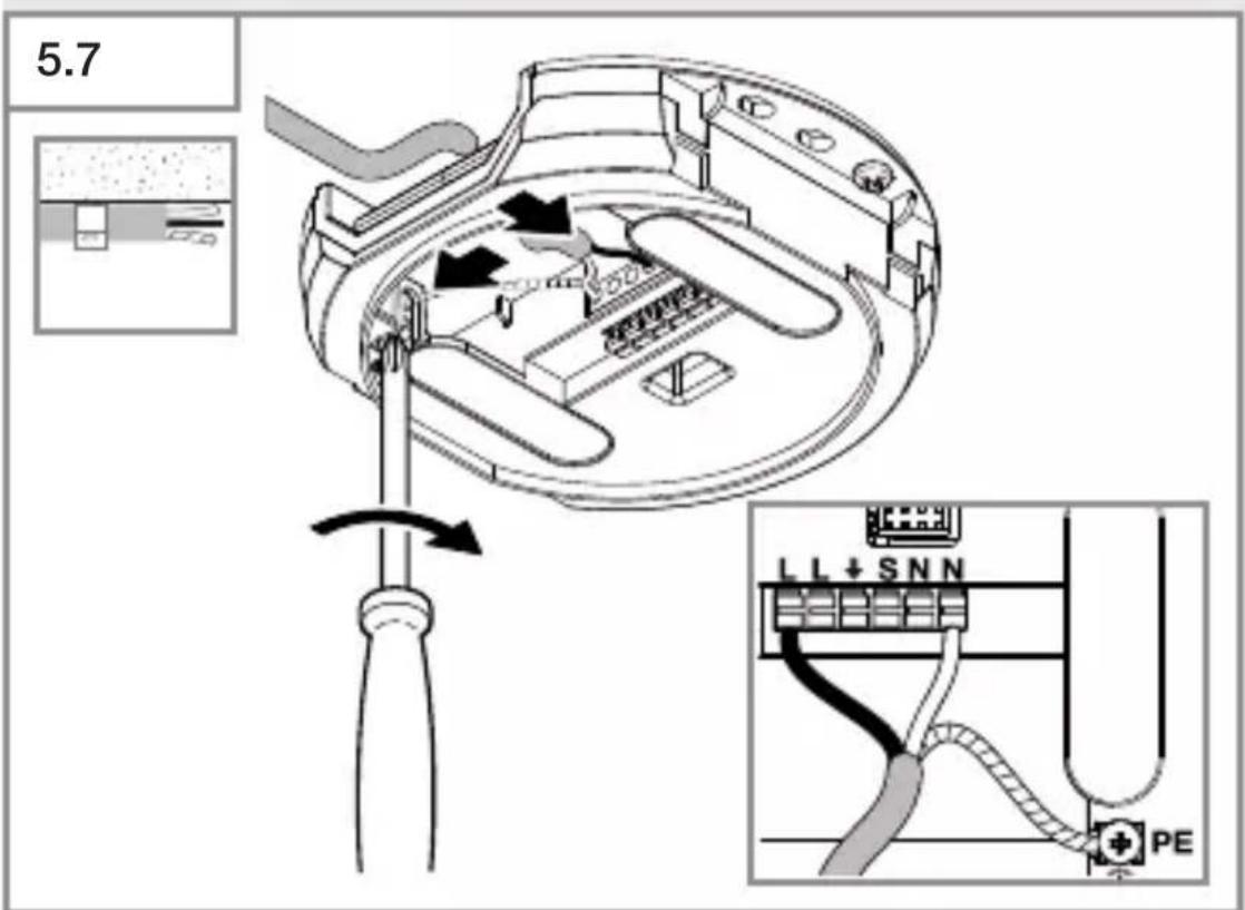
- Connect to mains power supply.
→"4. Electrical connection"
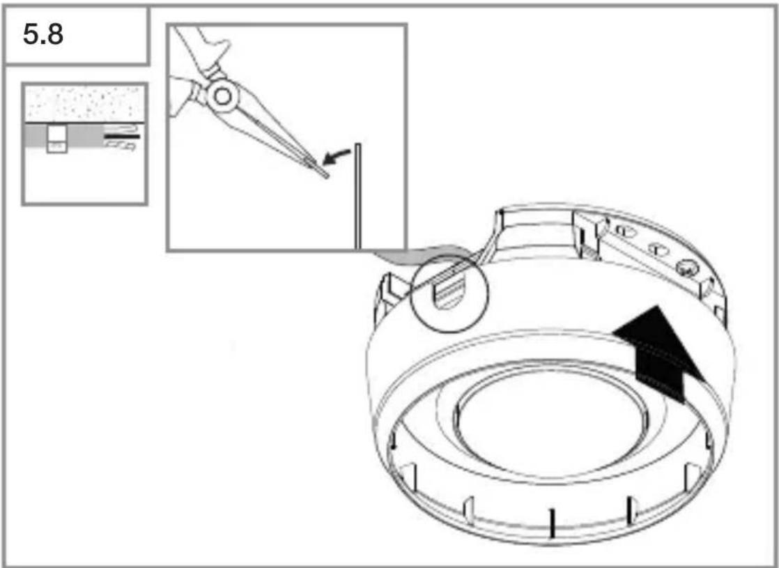
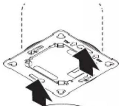
- Break out the mounting tab.
- Fit surface-mounting adapter.
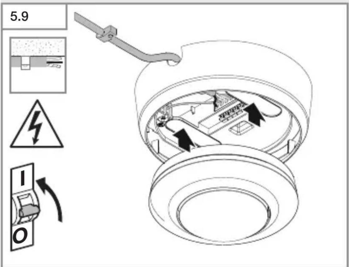
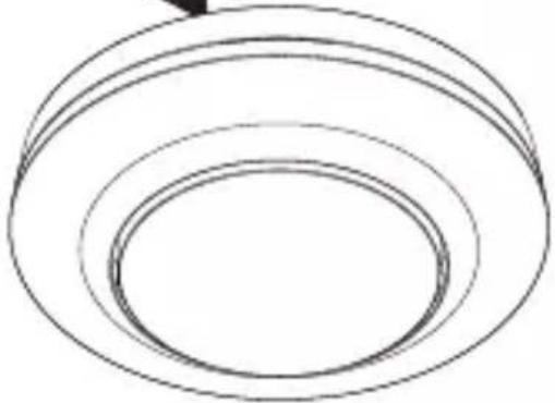
• Fit magnetic sensor module.
- Switch ON power supply.
Adjust detection reach
The shroud (included) can be used to adjust the detection zone to suit any specific need.
5.10
- Check to make sure the power supply is switched OFF.
- Detach sensor module from load module.
- Remove cover and lens.
- Cut shroud to size: shrouded lens segments shorten reach.
- Fit shroud into lens.
- Fasten lens with screws.
- Fit cover ring.
• Fit sensor module onto load module.
5.11


- Fit cover ring.
- Switch ON power supply.
- Make settings.
→"6. Function"
6. Function
Factory settings
The factory settings are activated when the sensor is put into operation for the first time as well as after resetting via the Smart Remote APP.
Twilight level: 500 lux
Time setting for COM1: 5 min
Fully / semi-automatic mode: fully automatic
Twilight setting
The chosen response threshold can be set from approx. 2 to 1,000 lux.
Daytime operation
When movement is detected, the sensor switches the load ON irrespective of ambient brightness.
Teach-IN
The Teach-IN function is to be selected at the level of light at which you want the sensor to respond to movement from now on. The level of ambient brightness measured in this way will be saved after 10 seconds. The load is deactivated during this period.
Time setting
The chosen stay-ON time can be set from a minimum of 5 seconds to a maximum of 60 minutes. If no movement is detected, the sensor switches OFF after the stay-ON time expires.
Operating mode
Semi-automatic mode
The light now only switches OFF automatically. Light is switched ON manually. Light must be requested using the button and stays ON for the time set.
Fully automatic mode
The light automatically switches ON and OFF in response to light level and human presence / movement. Light can be switched ON and OFF manually at any time. This temporarily interrupts the automatic switching function.
Presentation mode
If light is switched OFF via a push-button, the sensor activates the presentation mode. The load remains switched OFF until movement is detected. As soon as movement is no longer being detected and the stay-ON time has elapsed, the sensor returns to normal sensor mode.
Button input
The pushbutton switch connected provides the ON / OFF function and can switch lighting ON and OFF.
A pushbutton is required for operating the sensor in semi-automatic mode.
Manual override can be activated via a connected push-button switch. Pressing the pushbutton switch 2 x activates light ON for 4 hours. Pressing the pushbutton switch once again before the 4 hours ON period has elapsed returns the sensor to normal fully or semi-automatic mode.
For PD only: switches OFF in relation to ambient brightness
If light level falls below the selected twilight threshold, lighting is switched OFF even if movement or human presence is being detected.
Intelligent parallel connection of several sensors
L' detection provides the option of connecting as many as 10 sensors in parallel. When a sensor is triggered, light switches ON and all sensors in the network assume day-light mode. This has the advantage of being able to detect movements irrespectively of ambient brightness and letting stay-ON time expire.
LED function
Normal mode: LED OFF
Starting up: LED slowly flashes blue for 10 seconds
Initialisation: LED permanently lights up blue
Identification: The LED flashes blue slowly
Error: The LED flashes red rapidly
Test mode, no movement: LED permanently lights up green
Test mode, movement: LED rapidly flashes green
Teach-IN successfully completed: The LED lights up green for one second
Manual override 4H ON / OFF activated: LED permanently lights up cyan
Remote control command received: LED rapidly flashes cyan.
Semi-automatic mode set: LED slowly flashes cyan 5 x
Remote control RC5 (EAN 4007841 592806)
Additional functions RC5:
- Manual override 4 h ON / OFF
- User reset
Remote control RC8 (EAN 4007841 559410)
Additional functions RC8:
- Time setting CH1
- Test / normal mode
– Twilight setting
– Night-time operation
– Daylight operation
- Teach-IN
- Reset
Smart Remote
- Control via smartphone or tablet.
- Replaces remote controls RC5 and RC8.
- Load appropriate APP and connect via Bluetooth.
Additional functions, Smart Remote:
- Time setting: 5 s - 60 min
– Light-level setting: 2 – 1,000 lux, teach - Activate / deactivate remote control
- Test mode
– Fully automatic / semi-automatic - Manual override 4 h ON / OFF
- Reset
Smart Remote APP
To use the Smart Remote app, you will need a smartphone or tablet on which to download the app from the App Store / Play Store. Please note that your device must be able to support Bluetooth.
Android iOS


7. Maintenance and care
The tool requires no maintenance.
Hazard from electrical power.
Contact between water and live parts can result in electric shock, burns or death.
- Only clean tool in a dry state.
Risk of damage to property!
Using the wrong cleaning product can damage the light.
- Clean product with a moist cloth without detergent.
8. Disposal
Electrical and electronic equipment, accessories and packaging must be recycled in an environmentally compatible manner.

Do not dispose of electrical and electronic equipment as domestic waste.
EU countries only:
Under the current European Directive on Waste Electrical and Electronic Equipment and its implementation in national law, electrical and electronic equipment no longer suitable for use must be collected separately and recycled in an environmentally compatible manner.
9. Manufacturer's warranty
Manufacturer's warranty of STEINEL GmbH,
Diesel strasse 80-84, DE-33442 Herzebrock-Clarholz, Germany
All STEINEL products meet the highest quality standards.
For this reason, we, the manufacturer, are pleased to provide you, the customer, with a warranty under the following terms and conditions:
The warranty covers the absence of deficiencies which are proven to be the result of a material defect or fault in manufacturing and which are reported to us immediately after detection and within the warranty period. The warranty shall cover all STEINEL Professional products sold and used in Germany.
Our warranty cover for consumers
The provisions below apply to consumers. A consumer is any natural person who, on entering into the purchase transaction, neither acts in exercising their commercial nor their self-employed activity.
You can opt for warranty cover in the form of repair or replacement which will be provided free of charge (if applicable, in the form of a successor model of the same or higher quality) or in the form of a credit note.
In the case of sensors, floodlights, outdoor and indoor lights, the warranty period for the STEINEL Professional product you have purchased is 5 years in each case from the date on which the product was purchased.
We shall bear the shipping costs but not the transport risks involved in return shipment.
Our warranty cover for entrepreneurs
The provisions below apply to entrepreneurs. Entrepreneur is a natural or legal person or partnership with legal personality who or which, on entering into the purchase transaction, acts in exercising their or its commercial or self-employed activity.
We have the option of providing warranty cover by rectifying deficiencies free of charge, replacing a product free of charge (if applicable, in the form of a successor model of the same or higher quality) or by issuing a credit note.
In the case of sensors, floodlights, outdoor and indoor lights, the warranty period for the STEINEL Professional product you have purchased is 5 years in each case from the date on which the product was purchased.
Within the scope of warranty cover, we shall not bear your expenses accruing from subsequent fulfillment nor shall we bear your expenses for removing the defective product and installing a replacement product.
Statutory rights accruing from defects, gratuitousness
The warranty cover described here shall be applicable in addition to the statutory rights of warranty – including special consumer protection provisions – and shall not restrict or replace them. Exercising your statutory rights in the event of defects is gratuitous.
Exemptions from the warranty
All replaceable lamps are expressly excluded from this warranty.
– In addition to this, the warranty shall not cover:
– any wear resulting from use or any other natural wear of product parts or any deficiencies in the STEINEL Professional product that are attributable to wear caused by use or other natural wear,
– any improper or non-intended use of the product or any failure to observe the operating instructions,
– any unauthorised additions, alterations or other modifications to the product or any deficiencies attributable to the use of accessory,
– supplementary or replacement parts which are not genuine STEINEL parts,
– any maintenance or care of products that is not carried out in accordance with the operating instructions,
– any attachment or installation that is not in accordance with STEINEL’s installation instructions,
– any damage or loss occurring in transit.
Application of German law
The warranty shall be governed by German law excluding the United Nations Convention concerning the International Sale of Goods (CISG).
Making claims
If you wish to make a warranty claim, please send your product complete and carriage paid with the original receipt of purchase, which must show the date of purchase and product designation, either to your retailer or directly to us at STEINEL (UK) Ltd. – 25 Manasty Road, Axis Park, Orton Southgate, GB- Peterborough Cambs PE2 6UP United Kingdom. For this reason, we recommend that you keep your receipt of purchase in a safe place until the warranty period expires.
10. Technical specifications
- Dimensions ( × D )
MD / PD-8 ECO COM1: UP: 109 × 70 mm AP:
129 × 65 mm
DE: 109 × 109 mm
MD / PD-24 ECO COM1: UP: 109 × 75 mm AP:
129 × 70 mm
DE: 109 × 114 mm
- Input voltage: 220 - 240 V, 50/60 Hz
- Standby power consumption (P _sb ): < 0.1 W
– Time setting: COM1 relay 5 s – 60 min. - Twilight setting: 2–1,000 lux
- Reach (at a height of 2.5 m):
MD-8 ECO COM1: Tangential, ∅ 8.5 m Radial, ∅ 4.5 m
PD-8 ECO COM1: Tangential, ∅ 8.5 m Radial, ∅ 4.5 m
Human presence, ∅ 6.0 m
MD-24 ECO COM1: Tangential, ∅ 24.5 m Radial, ∅ 5.5 m
PD-24 ECO COM1: Tangential, ∅ 24.5 m Radial, ∅ 5.5 m
Human presence ∅ 7.5 m
- Angle of coverage: 360^
- Mounting height: 2.5 - 4 m
- Optimum mounting height: 2.8 m
- IP rating: IP 54 (surface-mounted version only)
- Temperature range: -20°C to +50°C
- Parallel connection via L': 10 sensors max.
Capacity, switching output 1 (COM1)
- Incandescent / halogen lamp load: 2,000 W
- LED / electronic ballast load (max. 50, c < 176 μF): 500 W
- Low-voltage halogen lamps: 2,000 VA
11. Troubleshooting
Light does not switch ON.
- No supply voltage.
- Check supply voltage.
- Lux setting too low.
- Slowly increase lux setting until light switches ON.
- No movement detection.
- Ensure unobstructed sensor vision.
- Check detection zone.
Lights do not switch OFF.
- Lux setting too high.
- Reduce lux setting.
- Stay-ON time elapsing.
- Wait until stay-ON time elapses; reduce stay-ON time if necessary.
- Interfering heat sources, e.g. fan heater, open doors and windows, pets, light bulb / halogen floodlight, moving objects.
- Check detection zone.
Sensor switches OFF despite persons being present.
- Stay-ON time too short.
- Increase stay-ON time.
– Light-level threshold too low.
- Change twilight setting.
Sensor does not switch OFF quickly enough.
- Stay-ON time too long.
- Reduce stay-ON time.
Sensor does not switch ON quickly enough when approached from the front.
- Reach is reduced when approached from the front.
• Install additional sensors.
- Adjust reach.
- Reduce distance between two sensors.
Sensor does not switch ON when persons are present despite it being dark
- Lux setting too low.
- Increase light-level threshold.
- Semi-automatic mode activated.
- Activate fully automatic mode or switch light ON at button.
- 4 hours OFF activated
- Deactivate 4 hours OFF
Sensor not connecting with the app.
- App or smartphone system crash.
- Restart mobile terminal device.
FR
Sommaire
natural_image
Technical line drawing of two mechanical components with concentric rings and a 1× scale indicator (no text or symbols on the components themselves)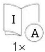
natural_image
Technical line drawing of two concentric cylindrical components with radial grid pattern, labeled '1×' (no text or symbols on the diagram itself)
natural_image
Technical line drawing of a mechanical component with concentric rings and mounting brackets (no text or symbols)
1×

1×

1×
natural_image
Simple line drawing of a cylindrical object with concentric rings (no text or symbols)
1× 1×

1×
max. 10 détecteurs
max. 10 détecteurs
FR
5. Montage

natural_image
Diagram of a computer motherboard with cable and socket components, showing internal wiring and mounting points (no text or labels)FR
natural_image
Technical diagram of a mechanical assembly with screw fasteners and a rotating shaft (no text or symbols)natural_image
Diagram of a mechanical component with arrows indicating direction (no text or symbols)
natural_image
Simple black-and-white diagram of a U-shaped magnet with two side charges and two arrows pointing outward (no text or symbols)
natural_image
Simple line drawing of concentric circular rings (no text or symbols)natural_image
Technical diagram of a mechanical device with internal components and directional arrows, no visible text or symbols
FR
Teach-IN (apprentissage)
- Teach-In (apprentissage)
Application Smart Remote

natural_image
Technical line drawing of two mechanical components with concentric rings and radial grooves (no text or symbols)1 × 1 ×

1×

- 1 sensor
- 1 afdekkap
- 1 veiligheidsinformatieblad (A)
- 1 Quick-Start-Guide (B)
natural_image
Technical line drawing of two concentric cylindrical components with radial grid patterns (no text or symbols)1 × 1 ×

1×

- 1 sensor
- 1 afdekkap
- 1 veiligheidsinformatieblad (A)
-1 Quick-Start-Guide (B)
A Belastingsmodule
B Potentiometerstift
C Aansluitklem
D Sensormodulel
natural_image
Technical line drawing of a mechanical component with concentric rings and mounting brackets (no text or symbols)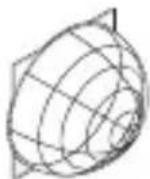
1 × 1 ×

1×

- 1 sensor
- 1 afdekkap
- 1 veiligheidsinformatieblad (A)
- 1 Quick-Start-Guide (B)
natural_image
Technical line drawing of a mechanical bearing or ring component (no text or symbols)
1 × 1 ×

1×
- 1 sensor
- 1 afdekkap
- 1 veiligheidsinformatieblad (A)
- 1 Quick-Start-Guide (B)
A Belastingsmodule
B Potentiometerstift
C Aansluitklem
D Sensormodule
Schakelschema COM1 inbouw – parallelle schakeling
4.3
max. 10 sensoren
NL
5. Montage

natural_image
Technical diagram of a mechanical assembly with screw fasteners and a rotating shaft (no text or symbols)natural_image
Diagram of a mechanical component with arrows indicating direction (no text or symbols)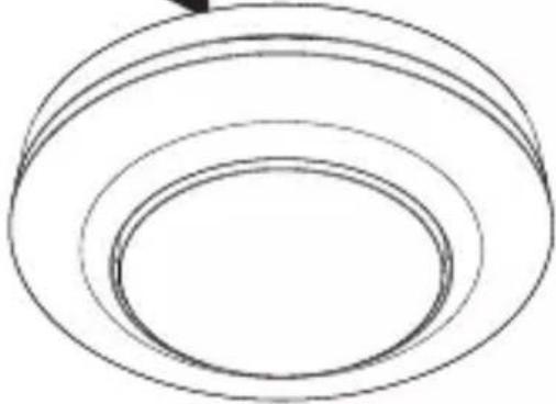
natural_image
Simple line drawing of concentric circular rings (no text or symbols)
natural_image
Simple black-and-white diagram of a U-shaped magnet with two side magnets and two lightning bolts below (no text or symbols)natural_image
Technical diagram of a mechanical device with internal components and directional arrows, no visible text or symbols
NL
Fout: led knippert snel rood
led brandt continu cyaan

natural_image
Technical line drawing of a mechanical bearing or ring component (no text or symbols)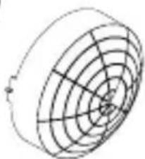
natural_image
Pure geometric diagram of concentric circles and radial lines without any text, numbers, or symbols1×
1×
1×
natural_image
Technical line drawing of a mechanical bearing or ring assembly (no text or symbols)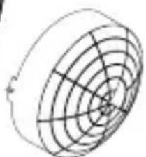
natural_image
Circular diagram with concentric rings and radial lines, no text or symbols present1×
1×
1×
natural_image
Technical line drawing of a mechanical component with concentric rings and a central hole (no text or symbols)
1 × 1 ×
1×

natural_image
Technical line drawing of a cylindrical mechanical component with concentric rings (no text or symbols)
1 × 1 ×

1×

max. 10 sensori
max. 10 sensori
IT
5. Montaggio

natural_image
Technical diagram of a mechanical assembly with screw fasteners and a rotating shaft (no text or symbols)natural_image
Diagram of a mechanical component with arrows indicating direction, no text or symbols present
natural_image
Simple black-and-white diagram of a U-shaped magnet with two side blocks and two directional arrows below (no text or symbols)
natural_image
Simple line drawing of concentric circular rings (no text or symbols)natural_image
Technical diagram of a mechanical device with internal components and directional arrows, no visible text or symbols

- Dimensioni (∅ × P)
MD / PD -8 ECO COM1: UP: 109 × 70 mm AP:
$$ 1 2 9 \times 6 5 m m $$
$$ D E: 1 0 9 \times 1 0 9 m m $$
MD / PD -24 ECO COM1: UP: 109 × 75 mm AP:
$$ 1 2 9 \times 7 0 m m $$
$$ D E: 1 0 9 \times 1 1 4 m m $$
- Tensione d'ingresso: 220 - 240 V, 50/60 Hz
- Potenza assorbita Standby (P _sb ): < 0,1 W
natural_image
Technical line drawing of two mechanical components with concentric rings and radial mesh patterns (no text or symbols)1 × 1 ×

natural_image
Technical line drawing of two cylindrical mechanical components with internal grid patterns (no text or symbols)1 × 1 ×

natural_image
Technical line drawing of a mechanical component with concentric rings and mounting brackets (no text or symbols)
1 × 1 ×

1×

natural_image
Technical line drawing of a mechanical bearing or ring component (no text or symbols)
1 × 1 ×

1×

máx. 10 sensores
máx. 10 sensores
5. Montaje
natural_image
Diagram of a computer motherboard with an open lid and cable, showing internal components and wiring (no text or labels)natural_image
Technical diagram of a mechanical assembly with arrows indicating direction of movement or force (no text or symbols present)natural_image
Diagram of a mechanical component with arrows indicating direction (no text or symbols)
natural_image
Simple black-and-white icon of a horseshoe magnet with two side blocks and two lightning bolts below (no text or symbols)
natural_image
Simple line drawing of concentric circular rings (no text or symbols)natural_image
Technical diagram of a mechanical device with internal components and directional arrows, no visible text or symbolsES


natural_image
Technical line drawing of two mechanical components with concentric rings and radial grooves (no text or symbols)1 × 1 ×
1×

natural_image
Technical line drawing of two concentric cylindrical components with radial grooves (no text or symbols)1 × 1 ×
1×

natural_image
Technical line drawing of a mechanical component with a circular housing and a wireframe sphere (no text or symbols)1 × 1 ×

1×

natural_image
Technical line drawing of a mechanical component with concentric rings and a separate 3D wireframe sphere (no text or symbols)
1 × 1 ×

1×

máx. 10 detetores
PT
PT
5. Montagem

natural_image
Diagram of a computer motherboard with an open lid and cable, showing internal components and wiring (no text or symbols)natural_image
Diagram of a mechanical assembly with arrows indicating motion or force direction (no text or symbols present)natural_image
Pure diagram of a mechanical component with arrows indicating direction, no text or symbols present
natural_image
Simple black-and-white diagram of a U-shaped magnet with two side blocks and two directional arrows below (no text or symbols)

natural_image
Simple line drawing of concentric circular rings (no text or symbols)natural_image
Technical diagram of a mechanical device with internal components and directional arrows, no visible text or symbols

natural_image
Technical line drawing of two mechanical components with concentric rings and radial grooves (no text or symbols)1 × 1 ×

- 1 sensor
- 1 täckram
- 1 säkerhetsdatablad (A)
- 1 quick-start guide (B)
natural_image
Technical line drawing of two concentric cylindrical components with radial grid patterns (no text or symbols)1 × 1 ×

- 1 sensor
- 1 täckram
- 1 säkerhetsdatablad (A)
- 1 quick-start guide (B)
A Inkopplingsbox
B Potistift
C Anslutningsplint
D Sensormodul
natural_image
Technical line drawing of a mechanical component with concentric rings and mounting bracket (no text or symbols)
1 × 1 ×
1×

- 1 sensor
- 1 täckram
- 1 säkerhetsdatablad (A)
- 1 quick-start guide (B)
natural_image
Simple line drawing of a cylindrical object with concentric rings (no text or symbols)
1 × 1 ×

1×

- 1 sensor
- 1 täckram
- 1 säkerhetsdatablad (A)
- 1 quick-start guide (B)
A Inkopplingsbox
B Potistift
C Anslutningsplint
D Sensormodul
Kopplingsschema COM1 infällt montage – parallelkoppling
4.3

max. 10 sensorer
SE
Kopplingsschema COM1 utanpåliggande montage
4.5

Kopplingsschema COM1 utanpåliggandemontage – parallelkoppling
4.6

max. 10 sensorer
SE
5. Montage

Fara p.g.a. elektrisk ström!
natural_image
Diagram of a computer motherboard with an open lid and cable, showing internal components and wiring (no text or symbols)natural_image
Technical diagram of a mechanical assembly with arrows indicating assembly direction (no text or symbols)natural_image
Diagram of a mechanical component with arrows indicating direction, no text or symbols present
natural_image
Simple black-and-white diagram of a U-shaped magnet with two square magnets and two directional arrows below (no text or symbols)
natural_image
Simple line drawing of concentric circular rings (no text or symbols)natural_image
Technical diagram of a mechanical device with internal components and directional arrows, no visible text or symbols

natural_image
Technical line drawing of two mechanical components with concentric rings and radial grooves (no text or symbols)1 × 1 ×

1×

natural_image
Technical line drawing of two cylindrical mechanical components with internal grid patterns (no text or symbols)1 × 1 ×
1×

A Lastmodul
B Potentiometerstift
C Tilslutningsklemme
D Sensormodul
natural_image
Technical line drawing of a mechanical component with concentric rings and mounting brackets (no text or symbols)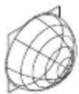
1 × 1 ×

1×

natural_image
Pure technical line drawing of a cylindrical mechanical part with concentric rings (no text or symbols)
1 × 1 ×

1×

A Lastmodul
B Potentiometerstift
C Tilslutningsklemme
D Sensormodul
max. 10 sensorer
DK
max. 10 sensorer
DK
5. Montering

natural_image
Diagram of a computer motherboard with an open lid and cable, showing internal components and wiring (no text or labels)natural_image
Technical diagram of a mechanical assembly with screw fasteners and a rotating shaft (no text or symbols)natural_image
Diagram of a mechanical component with arrows indicating direction (no text or symbols)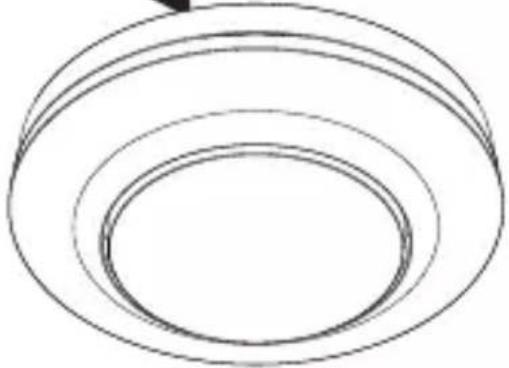
natural_image
Simple line drawing of concentric circular rings (no text or symbols)
natural_image
Simple black-and-white diagram of a U-shaped magnet with two side magnets and two lightning bolts below (no text or symbols)natural_image
Technical diagram of a mechanical device with internal components and directional arrows, no visible text or symbols
DK

Sensor slukker for sent.
natural_image
Technical line drawing of two mechanical components with concentric rings and radial grooves (no text or symbols)1 × 1 ×
1×

natural_image
Technical line drawing of two concentric cylindrical components with radial grid patterns (no text or symbols)1 × 1 ×
1×

natural_image
Technical line drawing of a mechanical component with concentric rings and mounting brackets (no text or symbols)
1×1×

1×

natural_image
Simple line drawing of a cylindrical mechanical component with concentric rings (no text or symbols)
1 × 1 ×

1×

max. 10 anturia
FI
FI
5. Asennus

natural_image
Diagram of a computer motherboard with an open lid and cable, showing internal components and wiring (no text or labels)natural_image
Technical diagram of a mechanical assembly with screw fasteners and a rotating shaft (no text or symbols)natural_image
Diagram of a mechanical component with arrows indicating direction (no text or symbols)
natural_image
Simple line drawing of concentric circular rings (no text or symbols)
natural_image
Simple black-and-white diagram of a U-shaped magnet with two side blocks and two directional arrows below (no text or symbols)natural_image
Technical diagram of a mechanical device with internal components and directional arrows, no visible text or symbols

7. Huolto ja hoito
natural_image
Technical line drawing of two mechanical components with concentric circular features (no text or symbols)1 × 1 ×
1×

- 1 sensor
- 1 dekkplate
- 1 sikkerhetsdatablad (A)
- 1 hurtigstart-guide (B)
Leveringsomfang MD / PD -8 ECO COM1 åpent
3.2

natural_image
Technical line drawing of two cylindrical mechanical components with internal grid patterns (no text or symbols)1 × 1 ×
1×

- 1 sensor
- 1 dekkplate
- 1 sikkerhetsdatablad (A)
- 1 hurtigstart-guide (B)
Produktmål MD / PD -8 ECO COM1 skjult
3.3

A Lastmodul
B Potensiometerstift
C Koblingsklemme
D Sensormodul
natural_image
Technical line drawing of a mechanical component with concentric circular features (no text or symbols)
1 × 1 ×

1×

- 1 sensor
- 1 dekkplate
- 1 sikkerhetsdatablad (A)
- 1 hurtigstart-guide (B))
Leveringsomfang MD / PD -24 ECO COM1 åpent
3.10

natural_image
Technical line drawing of a mechanical component with concentric circular grooves (no text or symbols)
1 × 1 ×

1×

- 1 sensor
- 1 dekkplate
- 1 sikkerhetsdatablad (A)
- 1 hurtigstart-guide (B)
Produktmål MD / PD -24 ECO COM1 skjult
3.11

A Lastmodul
B Potensiometerstift
C Koblingsklemme
D Sensormodul
maks. 10 sensorer
NO
Tilkobling av nettledning COM1 skjult
4.4
NO
5. Montering
natural_image
Diagram of a computer motherboard with an open lid and cable, showing internal components and wiring (no text or labels)natural_image
Technical diagram of a mechanical assembly with screw fasteners and a rotating shaft (no text or symbols)natural_image
Diagram of a mechanical component with arrows indicating direction, no text or symbols present
natural_image
Simple black-and-white diagram of a U-shaped magnet with two arrows pointing outward (no text or symbols)


natural_image
Simple line drawing of concentric circular rings (no text or symbols)- Sett den magnetiske sensormodulen på lastmodulen.
- Slå på strømtilførselen
natural_image
Technical diagram of a mechanical device with internal components and directional arrows, no visible text or symbols- Sjekk at strømtilførselen er stanset.
- Trekk sensormodulen av lastmodulen.
• Demonter dekkring og linse. - Klipp til dekkplaten:
Tildekkede linsesegmenter forkorter rekkevidden.
• Legg dekkplaten inn i linsen. - Fest linsen med skruer.
- Sett på dekkringen.
- Fest sensormodulen på lastmodulen.
5.11

NO

natural_image
Technical line drawing of two mechanical components with concentric circular features (no text or symbols)1 × 1 ×

1×

natural_image
Technical line drawing of two concentric cylindrical components with radial grooves (no text or symbols)1 × 1 ×
1×
natural_image
Technical line drawing of a mechanical component with concentric rings and mounting bracket (no text or symbols)
1 × 1 ×

1×

natural_image
Pure 3D diagram of concentric circular layers without any text, numbers, or symbols
1 × 1 ×

1×

μέγ. 10 αισθητήρες
μέγ. 10 αισθητήρες
5. Συναρμολόγηση

natural_image
Diagram of a computer motherboard with an open lid and cable, showing internal components and wiring (no text or symbols)natural_image
Technical diagram of a mechanical assembly with screw fasteners and a rotating shaft (no text or symbols)natural_image
Diagram of a mechanical component with arrows indicating direction (no text or symbols)
natural_image
Simple black-and-white diagram of a U-shaped magnet with two square magnets and two lightning bolts below (no text or symbols)
natural_image
Simple line drawing of three concentric ovals (no text or symbols)natural_image
Technical diagram of a mechanical device with internal components and directional arrows, no visible text or symbols
natural_image
Technical line drawing of two mechanical components with concentric rings and radial grooves (no text or symbols)1 × 1 ×

natural_image
Technical line drawing of two concentric cylindrical components with radial grid patterns (no text or symbols)1 × 1 ×

natural_image
Technical line drawing of a mechanical component with concentric rings and mounting brackets (no text or symbols)
1 × 1 ×

1×

natural_image
Technical line drawing of a mechanical bearing or ring component (no text or symbols)
1 × 1 ×

1×

maks. 10 sensör
TR
5. Montaj

natural_image
Technical diagram of a mechanical assembly with screw fasteners and a rotating shaft (no text or symbols)natural_image
Diagram of a mechanical component with arrows indicating direction (no text or symbols)
natural_image
Simple black-and-white diagram of a U-shaped magnet with two side blocks and two directional arrows below (no text or symbols)


natural_image
Simple line drawing of concentric circular rings (no text or symbols)natural_image
Technical diagram of a mechanical device with internal components and directional arrows, no visible text or symbols

7. Bakım ve koruma
natural_image
Technical line drawing of two mechanical components with concentric rings and radial mesh patterns (no text or symbols)1 × 1 ×
1×

natural_image
Technical line drawing of two cylindrical mechanical components with internal grid patterns (no text or symbols)1 × 1 ×
1×

natural_image
Technical line drawing of a mechanical component with concentric rings and mounting brackets (no text or symbols)
1 × 1 ×

1×

natural_image
Pure 3D diagram of concentric circular layers without any text, numbers, or symbols
1 × 1 ×

1×

max. 10 érzékelő
max. 10 érzékelő
HU
5. Szerelés
Áramütés veszélye!
natural_image
Technical diagram of a mechanical assembly with screw fasteners and a rotating component (no text or symbols)natural_image
Diagram of a mechanical component with arrows indicating direction (no text or symbols)
natural_image
Simple black-and-white diagram of a U-shaped magnet with magnetic field lines below (no text or symbols)
natural_image
Simple line drawing of concentric circular rings (no text or symbols)natural_image
Technical diagram of a mechanical component with arrows indicating assembly or movement, no visible text or symbols
natural_image
Technical line drawing of two mechanical components with concentric rings and radial grooves (no text or symbols)1 × 1 ×


natural_image
Technical line drawing of two concentric cylindrical components with radial grid patterns (no text or symbols)1 × 1 ×

natural_image
Technical line drawing of a mechanical component with a circular housing and a wireframe spherical mesh (no text or symbols)1 × 1 ×

1×

natural_image
Technical line drawing of a mechanical component with concentric rings and a separate 3D wireframe sphere (no text or symbols)
1 × 1 ×

1×

max. 10 senzorů
5. Montáž

natural_image
Diagram of a computer motherboard with an open lid and cable, showing internal components and wiring (no text or symbols)natural_image
Technical diagram of a mechanical assembly with arrows indicating assembly direction (no text or symbols)natural_image
Diagram of a device with arrows indicating directional movement or force, no text or symbols present
natural_image
Simple black-and-white diagram of a U-shaped magnet with two arrows pointing outward (no text or symbols)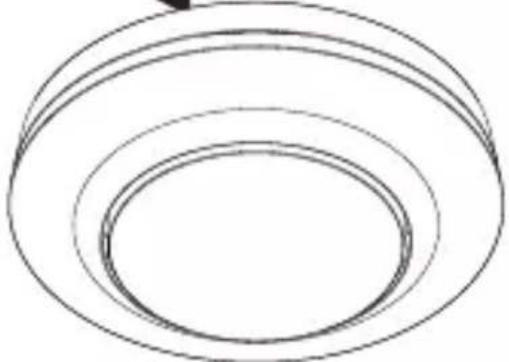
natural_image
Simple line drawing of concentric circular rings (no text or symbols)natural_image
Technical diagram of a mechanical device with internal components and directional arrows, no visible text or symbols

natural_image
Technical line drawing of two mechanical components with concentric rings and radial mesh patterns (no text or symbols)1 × 1 ×

natural_image
Technical line drawing of two cylindrical mechanical components with internal grid patterns (no text or symbols)1 × 1 ×

natural_image
Technical line drawing of a mechanical component with concentric rings and mounting bracket (no text or symbols)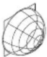
1 × 1 ×

1×

natural_image
Simple line drawing of a cylindrical object with concentric rings (no text or symbols)
1 × 1 ×

1×

Schéma zapojenia COM1 variant pod omietku – paralelné zapojenie
4.3

max. 10 senzorov
Pripojenie napájacieho vedenia COM1, variant pod omietku
4.4

SK
Schéma zapojenia COM1 variant na omietku
4.5
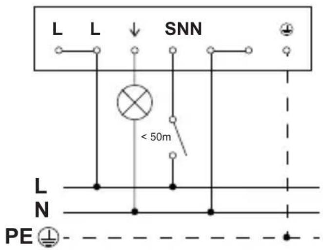
Schéma zapojenia COM1 variant na omietku – paralel-né zapojenie
4.6
max. 10 senzorov
Pripojenie napájacieho vedenia COM1, variant na omietku
4.7

SK
5. Montáž
natural_image
Diagram of a computer motherboard with an open lid and cable, showing internal components and wiring (no text or labels)natural_image
Technical diagram of a mechanical assembly with screw fasteners and a rotating shaft (no text or symbols)natural_image
Diagram of a mechanical component with arrows indicating direction, no text or symbols present
natural_image
Simple black-and-white diagram of a U-shaped magnet with two side magnets and two directional arrows below (no text or symbols)
natural_image
Simple line drawing of concentric circular rings (no text or symbols)natural_image
Technical diagram of a mechanical device with internal components and directional arrows, no visible text or symbols

natural_image
Technical line drawing of two mechanical components with concentric rings and radial grid patterns (no text or symbols)1 × 1 ×


natural_image
Technical line drawing of two mechanical components with concentric rings and a meshed base (no text or symbols)1 × 1 ×


natural_image
Technical line drawing of a mechanical component with concentric rings and mounting brackets (no text or symbols)
1 × 1 ×
1×
natural_image
Simple line drawing of a cylindrical object with concentric rings (no text or symbols)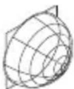
1 × 1 ×

1×

maks. 10 czujników
PL
maks. 10 czujników
PL
5. Montaż

natural_image
Diagram of a computer motherboard with an open lid and cable, showing internal components and wiring (no text or labels)natural_image
Technical diagram of a mechanical assembly with screw fasteners and a rotating shaft (no text or symbols)natural_image
Diagram of a mechanical component with arrows indicating direction, no text or symbols present
natural_image
Simple black-and-white diagram of a U-shaped magnet with two side magnets and two magnetic field lines below (no text or symbols)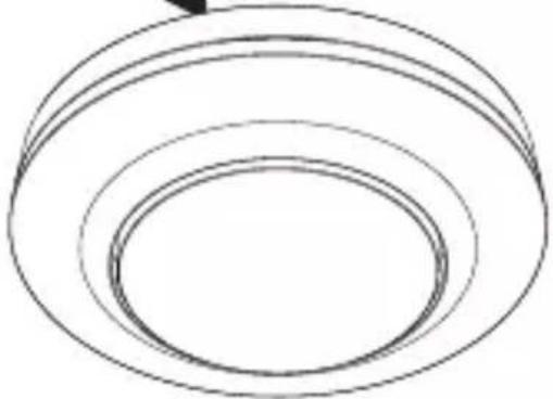
natural_image
Simple line drawing of concentric circular rings (no text or symbols)natural_image
Technical diagram of a mechanical component with arrows indicating assembly or movement, no visible text or symbols

natural_image
Technical line drawing of two mechanical components with concentric rings and radial grooves (no text or symbols)1 × 1 ×


natural_image
Technical line drawing of two concentric cylindrical components with radial grid patterns (no text or symbols)1 × 1 ×


natural_image
Technical line drawing of a mechanical component with concentric rings and mounting brackets (no text or symbols)
1 × 1 ×

1×

natural_image
Technical line drawing of a cylindrical mechanical component with concentric rings (no text or symbols)
1 × 1 ×

1×

max. 10 senzori
RO
max. 10 senzori
RO
5. Montaj

natural_image
Diagram of a computer motherboard with an open lid and cable, showing internal components and wiring (no text or labels)natural_image
Diagram of a mechanical assembly with screw fasteners and a rotating shaft (no text or symbols)natural_image
Diagram of a mechanical component with arrows indicating direction (no text or symbols)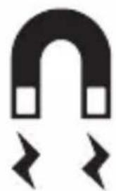
natural_image
Simple black-and-white diagram of a U-shaped magnet with two side blocks and two lightning bolts below (no text or symbols)
natural_image
Simple line drawing of concentric circular rings (no text or symbols)natural_image
Technical diagram of a mechanical device with internal components and directional arrows, no visible text or symbols
- Introduceti inelul de acoperire.
- Porniti alimentarea cu curent.
• Realizați reglajele.
→„6. Functionarea”
6. Functionarea
Reglaje din fabrică

5 ANI GARANTIA PRODUCATORULUI
10. Date tehnice
natural_image
Technical line drawing of two mechanical components with concentric rings and radial grooves (no text or symbols)1 × 1 ×

1×

- 1 Senzor
- 1 prekrivna skodelica
- 1 varnostni list (A)
- 1 navodilo za hiter zagon (B)
Obseg dobave MD / PD -8 ECO COM1 za nadomet
3.2
natural_image
Technical line drawing of two concentric cylindrical components with radial grid patterns (no text or symbols)1 × 1 ×
1×
- 1 Senzor
- 1 prekrivna skodelica
- 1 varnostni list (A)
- 1 navodilo za hiter zagon (B)
Mere izdelka MD / PD -8 ECO COM1 podomet
3.3
Mere izdelka MD / PD -8 ECO COM1 nadomet
3.4
SI
Pregled naprav MD / PD -8 ECO COM1 podo-met
3.5
A Močnostni modul
B Gumb za potencimeter
C Priključna sponka
D Senzorski modul
Pregled naprav MD / PD -8 ECO COM1 nado-met
3.6

A Nadometni adapter
B Senzorski modul
C Priključna sponka
D Prekrivni obroč
natural_image
Technical line drawing of a mechanical component with concentric circular features and a central dot (no text or symbols)
1 × 1 ×

1×

- 1 Senzor
- 1 prekrivna skodelica
- 1 varnostni list (A)
- 1 navodilo za hiter zagon (B)
Obseg dobave MD / PD -24 ECO COM1 za nadomet
3.10
natural_image
Simple line drawing of a cylindrical mechanical component with concentric rings (no text or symbols)
1 × 1 ×

1×

- 1 Senzor
- 1 prekrivna skodelica
- 1 varnostni list (A)
- 1 navodilo za hiter zagon (B)
Mere izdelka MD / PD -24 ECO COM1 podomet
3.11
Mere izdelka MD / PD -24 ECO COM1 nadomet
3.12
Pregled naprav MD / PD -24 ECO COM1 podomet
3.13
A Močnostni modul
B Gumb za potencimeter
C Priključna sponka
D Senzorski modul
Pregled naprav MD / PD -24 ECO COM1 nadomet
3.14

A Nadometni adapter
B Senzorski modul
C Priključna sponka
D Prekrivni obroč
max. 10 senzorjev
Priklop dovoda omrežja COM1 podomet
4.4
SI
SI
5. Montaža

natural_image
Diagram of a computer motherboard with an open lid and cable, showing internal components and wiring (no text or symbols)- Preverite, ali je dovod napetosti izklopljen.
- Izvedite omrežni priključek.
natural_image
Diagram of a mechanical assembly with screw fasteners and a rotating shaft (no text or symbols)natural_image
Diagram of a mechanical component with arrows indicating direction (no text or symbols)
natural_image
Simple black-and-white diagram of a horseshoe magnet with two arrows pointing outward (no text or symbols)
natural_image
Simple line drawing of three concentric ovals (no text or symbols)natural_image
Technical diagram of a mechanical device with internal components and directional arrows, no visible text or symbols- Preverite, ali je dovod napetosti izklopljen.
• Zarišite luknje za vrtanje.
5.5


natural_image
Technical line drawing of two mechanical components with concentric rings and radial grid lines (no text or symbols)1 × 1 ×


- 1 senzor
- 1 pokrivni zaslon
- 1 sigurnosno tehnički list (A)
- 1 uputa za brzo pokretanje (B)
natural_image
Technical line drawing of two mechanical components with concentric rings and radial grooves (no text or symbols)1 × 1 ×


- 1 senzor
- 1 pokrivni zaslon
- 1 sigurnosno tehnički list (A)
- 1 uputa za brzo pokretanje (B)
Dimenzije proizvoda MD / PD -8 ECO COM1 za podžbuknu instalaciju
3.3
Dimenzije proizvoda MD / PD -8 ECO COM1 za nadžbuknu instalaciju
3.4

HR
Pregled uređaja MD / PD -8 ECO COM1, podžbukna instalacija
3.5

A modul opterećenja
B kontakt potenciometra
C Priključna stezaljka
D senzorski modul
Pregled uređaja MD / PD -8 ECO COM1, nadžbukna instalacija
3.6
A nadžbukni adapter
B senzorski modul
C Priključna stezaljka
D prsten poklopca
HR
natural_image
Technical line drawing of a mechanical component with concentric rings and mounting bracket (no text or symbols)
1 × 1 ×

1×

- 1 senzor
- 1 pokrivni zaslon
- 1 sigurnosno tehnički list (A)
- 1 uputa za brzo pokretanje (B)
natural_image
Pure technical line drawing of a cylindrical mechanical part with concentric rings (no text or symbols)
1 × 1 ×
1×

- 1 senzor
- 1 pokrivni zaslon
- 1 sigurnosno tehnički list (A)
- 1 uputa za brzo pokretanje (B)
Dimenzije proizvoda MD / PD -24 ECO COM1 za podžbuknu instalaciju
3.11

Dimenzije proizvoda MD / PD -24 ECO COM1 za nadžbuknu instalaciju
3.12
Pregled uređaja MD / PD -24 ECO COM1, podžbukna instalacija
3.13

A modul opterećenja
B kontakt potenciometra
C Priključna stezaljka
D senzorski modul
Pregled uređaja MD / PD -24 ECO COM1, nadžbukna instalacija
3.14

A nadžbukni adapter
B senzorski modul
C Priključna stezaljka
D prsten poklopca
Shema priključivanja COM1 podžbukna instalacija – paralelni spoj
4.3
maks. 10 senzora
Priključak podžbuknog mrežnog voda COM1
4.4
HR
maks. 10 senzora
HR
5. Montaža

natural_image
Diagram of a computer motherboard with an open lid and cable, showing internal components and wiring (no text or symbols)natural_image
Technical diagram of a mechanical assembly with screw fasteners and a rotating shaft (no text or symbols)- Modul opterećenja pričvrstite na ugradbenu kutiju.
5.3

natural_image
Diagram of a mechanical component with arrows indicating direction (no text or symbols)
natural_image
Simple black-and-white diagram of a U-shaped magnet with two side magnets and two magnetic field lines below (no text or symbols)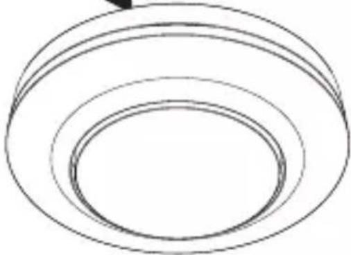
natural_image
Simple line drawing of concentric circular rings (no text or symbols)natural_image
Technical diagram of a mechanical device with internal components and directional arrows, no visible text or symbols- Provjerite je li isključeno naponsko napajanje.
- Odvojite senzorski modul od modula opterećenja.
• Demontirajte prsten poklopca i leću. - Izrežite pokrivni zaslon: prekriveni segmenti leće smanjuju domet.
- Umetnite pokrivni zaslon u leću.
- Pričvrstite leću vijcima.
• Stavite prsten poklopca. - Senzorski modul namjestite na modul opterećenja.
5.11


• Stavite prsten poklopca.
- Uključite strujno napajanje.
- Izvršite podešavanja.
→„6. Funkcija“
HR
6. Funkcija
Tvorničke postavke
Prilikom prvog puštanja senzora u rad kao i resetiranja pomoću aplikacije Smart Remote aktiviraju se tvorničke postavke.

natural_image
Technical line drawing of two mechanical components with concentric rings and radial grid lines (no text or symbols)1 × 1 ×


natural_image
Technical line drawing of two cylindrical mechanical components with internal grid patterns (no text or symbols)1 × 1 ×


natural_image
Technical line drawing of a mechanical component with a 3D wireframe view and a separate 2D mesh detail (no text or symbols)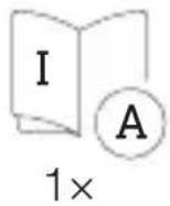

natural_image
Technical drawing of a cylindrical mechanical part with concentric rings and a separate wireframe sphere labeled 1×1× (no text or symbols on the diagram itself)

Lülitite plaan COM1, süvispaigaldatav – paralleellülitus
4.3
max. 10 sensorit
EE
Lülitite plaan COM1, pindpaigaldatav
4.5
Lülitite plaan COM1, pindpaigaldatav – paralleellülitus
4.6
max. 10 sensorit
EE
5. Montaaž

Elektrilöögi oht!
natural_image
Technical diagram of a mechanical assembly with screw fasteners and a rotating shaft (no text or symbols)- Kinnitage koormusmoodul kruvidega paigalduspesale.
5.3

natural_image
Diagram of a mechanical component with arrows indicating direction (no text or symbols)
natural_image
Simple black-and-white diagram of a U-shaped magnet with two side blocks and two lightning bolts below (no text or symbols)
natural_image
Simple line drawing of concentric circular rings (no text or symbols)- Asetage magnetiline sensorimoodul koormusmoodulile.
• Lülitage voolutoide sisse.
Pindpaigalduse paigaldussammud
5.4

natural_image
Technical diagram of a mechanical device with internal components and directional arrows, no visible text or symbols
• Paigaldage katterõngas.
• Lülitage voolutoide sisse.
- Teostage seaded.
→“6. Talitlus”
EE
6. Talitlus
Tehaseseadistused

natural_image
Technical line drawing of two mechanical components with concentric rings and radial grid patterns (no text or symbols)1 × 1 ×


natural_image
Technical line drawing of two cylindrical mechanical components with internal grid patterns (no text or symbols)1 × 1 ×


A Apkrovos modulis
B Potenciometro kištukas
C Gnybtai
D Sensoriaus modulis
natural_image
Technical line drawing of a mechanical component with concentric rings and mounting brackets (no text or symbols)
1 × 1 ×

1×

natural_image
Simple line drawing of a cylindrical object with concentric rings (no text or symbols)
1 × 1 ×

1×

A Apkrovos modulis
B Potenciometro kištukas
C Gnybtai
D Sensoriaus modulis
Sujungimo schema COM1 potinkinis montavimas – Lygiagretus jungimas
4.3

maks. 10 jutiklių
Maitinimo kabelio prijungimas COM1 potinkinis montavimas
4.4

LT
maks. 10 jutiklių
LT
5. Montavimas

natural_image
Diagram of a computer motherboard with an open lid and cable, showing internal components and wiring (no text or symbols)natural_image
Technical diagram of a mechanical assembly with screw fasteners and a rotating shaft (no text or symbols)natural_image
Diagram of a mechanical component with arrows indicating direction (no text or symbols)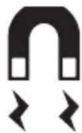
natural_image
Simple black-and-white diagram of a horseshoe magnet with two lightning bolts below (no text or symbols)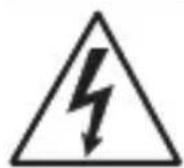

natural_image
Simple line drawing of three concentric ovals (no text or symbols)natural_image
Technical diagram of a mechanical device with internal components and directional arrows, no visible text or symbols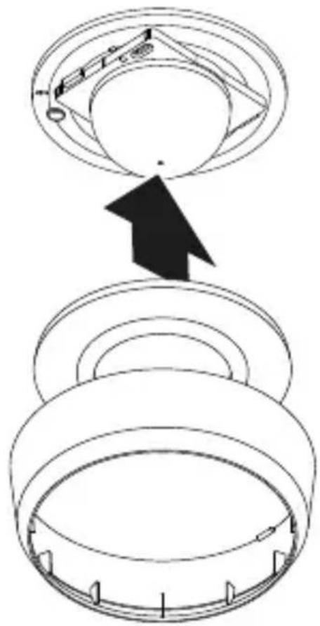

natural_image
Technical line drawing of two mechanical components with concentric rings and radial grid lines (no text or symbols)1 × 1 ×

1×
- 1 sensors
- 1 nosegs
- 1 Drošības datu lapa (A)
- 1 Ātrais starts (B)
Piegādes apjoms MD / PD -8 ECO COM1 virsapmetuma
3.2
natural_image
Technical line drawing of two cylindrical mechanical components with internal grid patterns (no text or symbols)1 × 1 ×
1×

- 1 sensors
- 1 nosegs
- 1 Drošības datu lapa (A)
- 1 trais starts (B)
Preces izmēri MD / PD -8 ECO COM1 zemapmetuma
3.3
Preces izmēri MD / PD -8 ECO COM1 virsapmetuma
3.4
LV
A Slodzes modulis
B Potenciometra štifts
C Pieslēguma aizspiednis
D Sensora modulis
natural_image
Technical line drawing of a mechanical component with concentric rings and mounting bracket (no text or symbols)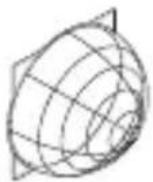
1 × 1 ×

1×

- 1 sensors
- 1 nosegs
- 1 Drošības datu lapa (A)
- 1 Ātrais starts (B)
Piegãdes apjoms MD / PD -24 ECO COM1 virsapmetuma
3.10

natural_image
Simple line drawing of a cylindrical object with concentric rings (no text or symbols)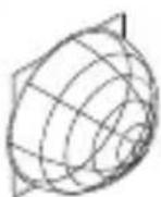
1 × 1 ×

1×

- 1 sensors
- 1 nosegs
- 1 Drošības datu lapa (A)
- 1 Atrais starts (B)
LV
Preces izmēri MD / PD -24 ECO COM1 zemapmetuma
3.11
Preces izmēri MD / PD -24 ECO COM1 virsapmetuma
3.12
A Slodzes modulis
B Potenciometra štifts
C Pieslēguma aizspiednis
D Sensora modulis
LV
maks. 10 sensori
Elektrotikla pievadvada pieslēgums COM1 zemapmetuma
4.4
LV
maks. 10 sensori
Elektrotikla pievadvada pieslēgums COM1 virsapmetuma
4.7
LV
5. Montāža

natural_image
Diagram of a computer motherboard with an open lid and cable, showing internal components and wiring (no text or labels)natural_image
Technical diagram of a mechanical assembly with screw fasteners and a rotating shaft (no text or symbols)natural_image
Diagram of a mechanical component with arrows indicating direction (no text or symbols)
natural_image
Simple black-and-white icon of a horseshoe magnet with two square magnets and two lightning bolts below (no text or symbols)
natural_image
Simple line drawing of concentric circular rings (no text or symbols)natural_image
Technical diagram of a mechanical device with internal components and directional arrows, no visible text or symbols

natural_image
Technical line drawing of two mechanical components with concentric rings and radial mesh patterns (no text or symbols)1 × 1 ×


natural_image
Technical line drawing of two cylindrical mechanical components with internal grid patterns (no text or symbols)1 × 1 ×

natural_image
Technical line drawing of a mechanical component with concentric rings and mounting brackets (no text or symbols)
1 × 1 ×

1×

natural_image
Pure 3D diagram of concentric circular layers without any text, numbers, or symbols
1 × 1 ×

1×

макс. 10 сензора
макс. 10 сензора
5. Монтаж

natural_image
Technical diagram of a mechanical assembly with screw fasteners and a rotating shaft (no text or symbols)natural_image
Diagram of a mechanical component with arrows indicating direction (no text or symbols)
natural_image
Simple black-and-white diagram of a U-shaped magnet with two arrows pointing outward (no text or symbols)


natural_image
Simple line drawing of concentric circular rings (no text or symbols)natural_image
Technical diagram of a mechanical device with internal components and directional arrows, no visible text or symbols
natural_image
Technical line drawing of two mechanical components with concentric circular features (no text or symbols)1 × 1 ×
1×
natural_image
Technical line drawing of two cylindrical components with internal grid patterns (no text or symbols)1 × 1 ×

1×
natural_image
Technical line drawing of a mechanical component with concentric rings and mounting brackets (no text or symbols)
1 × 1 ×
1×

natural_image
Simple line drawing of a cylindrical object with concentric rings (no text or symbols)
1 × 1 ×

1×
CN
4. 电气连接
最多 10 个传感器
暗装 COM1 电源线连接
4.4
原理图 COM1 表面贴装
4.5
原理图 COM1 表面贴装, 并联电路
4.6
最多 10 个传感器
明装 COM1 电源线连接
4.7

5. 安装
触电危险!
接触导电部件可能造成电击、灼伤或死亡。
natural_image
Diagram of a computer motherboard with an open lid and cable, showing internal components and wiring (no text or symbols)natural_image
Technical diagram of a mechanical assembly with screw fasteners and a rotating shaft (no text or symbols)- 将负载模块拧到插座上。
5.3


natural_image
Diagram of a mechanical component with arrows indicating direction (no text or symbols)
natural_image
Simple line drawing of concentric circular rings (no text or symbols)
natural_image
Simple black-and-white diagram of a U-shaped magnet with two side blocks and two directional arrows below (no text or symbols)natural_image
Technical diagram of a mechanical device with internal components and a pencil tip, no visible text or symbols- 检查电源是否已切断。
- 标记钻孔。
5.5

- 插上盖环。
- 接通电源。
- 进行设置。
→ “6. 功能”
6. 功能
出厂设置
iOS

7. 维护和保养
设备免维护。

触电危险!
natural_image
Technical line drawing of two mechanical components with concentric rings and radial mesh patterns (no text or symbols)1 × 1 ×


natural_image
Technical line drawing of two mechanical components with concentric rings and a meshed base (no text or symbols)1 × 1 ×

natural_image
Technical line drawing of a mechanical component with concentric rings and mounting bracket (no text or symbols)
1 × 1 ×

1×

natural_image
Pure 3D diagram of concentric circular layers without any text, numbers, or symbols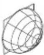
1 × 1 ×

1×

макс. 10 сенсоров
макс. 10 сенсоров
5. Монтаж

natural_image
Diagram of a computer motherboard with an open lid and cable, showing internal components and wiring (no text or symbols)natural_image
Technical diagram of a mechanical assembly with screw fasteners and a rotating shaft (no text or symbols)natural_image
Diagram of a mechanical component with arrows indicating direction, no text or symbols present
natural_image
Simple black-and-white diagram of a U-shaped magnet with two side blocks and two directional arrows below (no text or symbols)
natural_image
Simple line drawing of three concentric circular rings (no text or symbols)natural_image
Technical diagram of a mechanical component with arrows indicating assembly or movement, no visible text or symbols