
GSC 10 - Cadence and speed sensor GARMIN - Free user manual and instructions
Find the device manual for free GSC 10 GARMIN in PDF.



User questions about GSC 10 GARMIN
0 question about this device. Answer the ones you know or ask your own.
Ask a new question about this device
Download the instructions for your Cadence and speed sensor in PDF format for free! Find your manual GSC 10 - GARMIN and take your electronic device back in hand. On this page are published all the documents necessary for the use of your device. GSC 10 by GARMIN.
USER MANUAL GSC 10 GARMIN
natural_image
Black Garmin GARMIN robotic device with handle and control knob (no visible text or symbols)instructions (EN)
instructions (FR)
istruzioni (IT)
anweisungen (DE)
instrucciones (ES)
instruções (PT)
instructies (NL)
instruktioner (DA)
ohjeet (FI)
instruksjoner (NO)
instruktioner (SV)
Installing the GSC 10

WARNING
See the Important Safety and Product Information guide in the Forerunner® or the Edge® product box for product warnings and other important information.
Both magnets must be aligned with their respective indication lines.
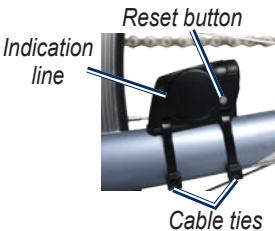
- Place the GSC 10 on the rear chain stay (on the side opposite the drive train).
NOTE: Place the flat rubber pad or the triangle-shaped rubber pad between the GSC 10 and the chain stay for stability.
text_image
Indication line Reset button Cable tiesGSC 10 on Rear Chain Stay
-
Loosely attach the GSC 10 using two cable ties.
-
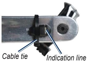
Attach the pedal magnet to the crank arm using the adhesive mount and a cable tie.
The pedal magnet must be within 5 mm of the GSC 10. The indication line on the pedal magnet must line up with the indication line on the GSC 10.
text_image
Cable tie Indication linePedal Magnet on Crank Arm
-
Unscrew the spoke magnet from the plastic piece.
-
Place the spoke in the groove of the plastic piece and tighten slightly.
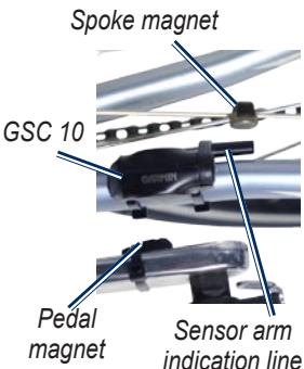
The spoke magnet can face away from the GSC 10 if there is not enough room between the sensor arm and the spoke. The spoke magnet must line up with the indication line on the sensor arm.
text_image
Spoke magnet GSC 10 Pedal magnet Sensor arm indication lineGSC 10 and Magnet Alignment
- Loosen the screw on the sensor arm.
- Move the sensor arm to within 5 mm of the spoke magnet.
You can also tilt the GSC 10 closer to either magnet for improved alignment.
- Press the Reset button on the GSC 10.
The LED turns red, then green.
- Pedal to test the sensor alignment.
The red LED blinks each time the pedal magnet passes the sensor. The green LED blinks each time the spoke magnet passes the sensor arm.
NOTE: The LED blinks for the first 60 passes after a reset. Press Reset again if you require additional passes.
- When everything is aligned and working correctly, tighten the cable ties, the sensor arm, and the spoke magnet.
Pair the Sensors
Pairing is the connecting of ANT ^+™ wireless sensors, for instance your GSC 10 with an Edge. After you pair the first time, your Edge automatically recognizes your GSC 10 each time it is activated.
NOTE: The pairing settings differ for each compatible Forerunner and Edge model. See your owner's manual.
GSC 10 Battery
WARNING
Do not use a sharp object to remove user-replaceable batteries. Contact your local waste disposal department to properly recycle the batteries.
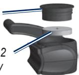
The GSC 10 contains a user-replaceable CR2032 battery.
- Locate the circular battery cover on the side of the GSC 10.
Battery cover
CR2032 battery
natural_image
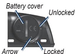
3D mechanical component diagram showing a lever and shaft assembly (no text or symbols)- Use a coin to twist the cover counter-clockwise until it is loose enough to remove (the arrow points to unlocked).
- Remove the cover and battery.
- Wait 30 seconds.
- Insert the new battery with the positive side facing up.
NOTE: Be careful not to damage or lose the O-ring gasket on the cover.
- Use a coin to twist the cover back into place (the arrow points to locked).
text_image
Battery cover Unlocked Arrow LockedTechnical Specifications
Physical size: W × H × D: 2.0 × 1.2 × 0.9 in. (5.1 × 3.0 × 2.3 cm)
Weight: 0.9 oz. (25 g)
Water resistance: IPX7
Transmission range: approximately 9.8 ft. (3 m)
Battery: user-replaceable CR2032 (3 volts) Perchlorate Material – special handling may apply. See www.dtsc.ca.gov /hazardouswaste /perchlorate.
Battery life: approximately 1.4 years (1 hour per day)
Operating temperature range: from 5°F to 158°F (from -15°C to 70°C)
Radio frequency/ protocol: 2.4 GHz/ ANT+ wireless communications protocol
System Compatibility: ANT+
Limited Warranty
Garmin's standard limited warranty applies to this accessory. See the Important Safety and Product Information guide in the Forerunner or the Edge product box.
natural_image
3D mechanical assembly diagram showing a lever and shaft assembly (no text or symbols)GSC 10 takahaarukassa
© 2010 Garmin Ltd. or its subsidiaries
Garmin International, Inc., 1200 East 151st Street, Olathe, Kansas 66062, USA Tel. (913) 397.8200 or (800) 800.1020 Fax (913) 397.8282
Garmin (Europe) Ltd., Liberty House, Hounsdown Business Park, Southampton, Hampshire, SO40 9LR UK Tel. +44 (0) 870.8501241 (outside the UK) 0808 2380000 (within the UK) Fax +44 (0) 870.8501251
Garmin Corporation, No. 68, Jangshu 2nd Road, Sijhih, Taipei County, Taiwan Tel. 886/2.2642.9199 Fax 886/2.2642.9099
Garmin ^® , the Garmin logo, Forerunner ^® , Edge ^® , Dynastream ^™ , ANT ^™ , and ANT+ ^™ are trademarks of Garmin Ltd. or its subsidiaries, registered in the USA and other countries. These trademarks may not be used without the express permission of Garmin. Other trademarks and trade names are those of their respective owners.

text_image
GARMIN®

For the latest product information and accessories, visit the Garmin Web site at www.garmin.com.
January 2010
Part Number 190-00646-01 Rev. C