PSB 401/1 - Drill Prowork - Free user manual and instructions
Find the device manual for free PSB 401/1 Prowork in PDF.
| Product type | Drill press |
| Brand | Prowork |
| Model | PSB 401/1 |
| Input voltage | 230 V - 50 Hz |
| Rated power | 350 W |
| Operating mode | S2 15 min (intermittent duty) |
| Motor speed | 1400 rpm |
| Speed range | 580 - 2650 rpm (5 speeds) |
| Chuck housing | B16 |
| Gear chuck | Ø 1.5 - 13 mm |
| Max. stem diameter | 13 mm |
| Spindle axis to frame distance | 104 mm |
| Drilling depth | 50 mm |
| Column diameter | 46 mm |
| Height | 590 mm |
| Weight | 18 kg |
| Sound pressure level | 61.5 dB(A) |
| Sound power level | 74.5 dB(A) |
| Hand-arm vibration | < 2.5 m/s² |
| Machinable materials | Metal, plastic, wood |
| Main functions | Drilling, chamfering, center drilling |
| Maintenance and cleaning | Clean with dry cloth, grease exposed parts (column, table), no harsh solvents |
| Safety | Safety switch on cover, zero voltage release, foldable chip guard |
| Spare parts and repairability | Orders via ISC GmbH, repairs by qualified electrician |
| General information | 2-year warranty, household use only |
Frequently Asked Questions - PSB 401/1 Prowork
User questions about PSB 401/1 Prowork
0 question about this device. Answer the ones you know or ask your own.
Ask a new question about this device
Download the instructions for your Drill in PDF format for free! Find your manual PSB 401/1 - Prowork and take your electronic device back in hand. On this page are published all the documents necessary for the use of your device. PSB 401/1 by Prowork.
USER MANUAL PSB 401/1 Prowork
text_image
Labeled diagram of a drill press with numbered parts for identification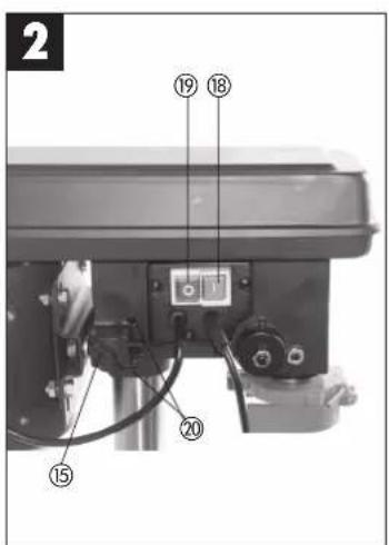
text_image
2 ⑲ ⑱ ⑲ ⑳ ⑲ ⑳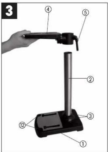
text_image
3 ① ② ③ ④ ⑤
3
text_image
4 ② ① ⑦ ③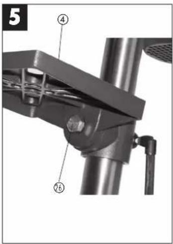
text_image
5 ④ ⑥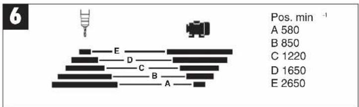
bar
| Category | Value | |---|---| | A | 580 | | B | 850 | | C | 1220 | | D | 1650 | | E | 2650 |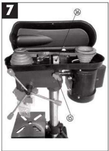
text_image
7 ⑯ ⑮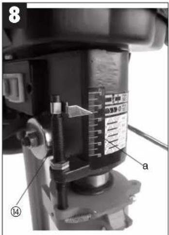
text_image
8 a ⑭D
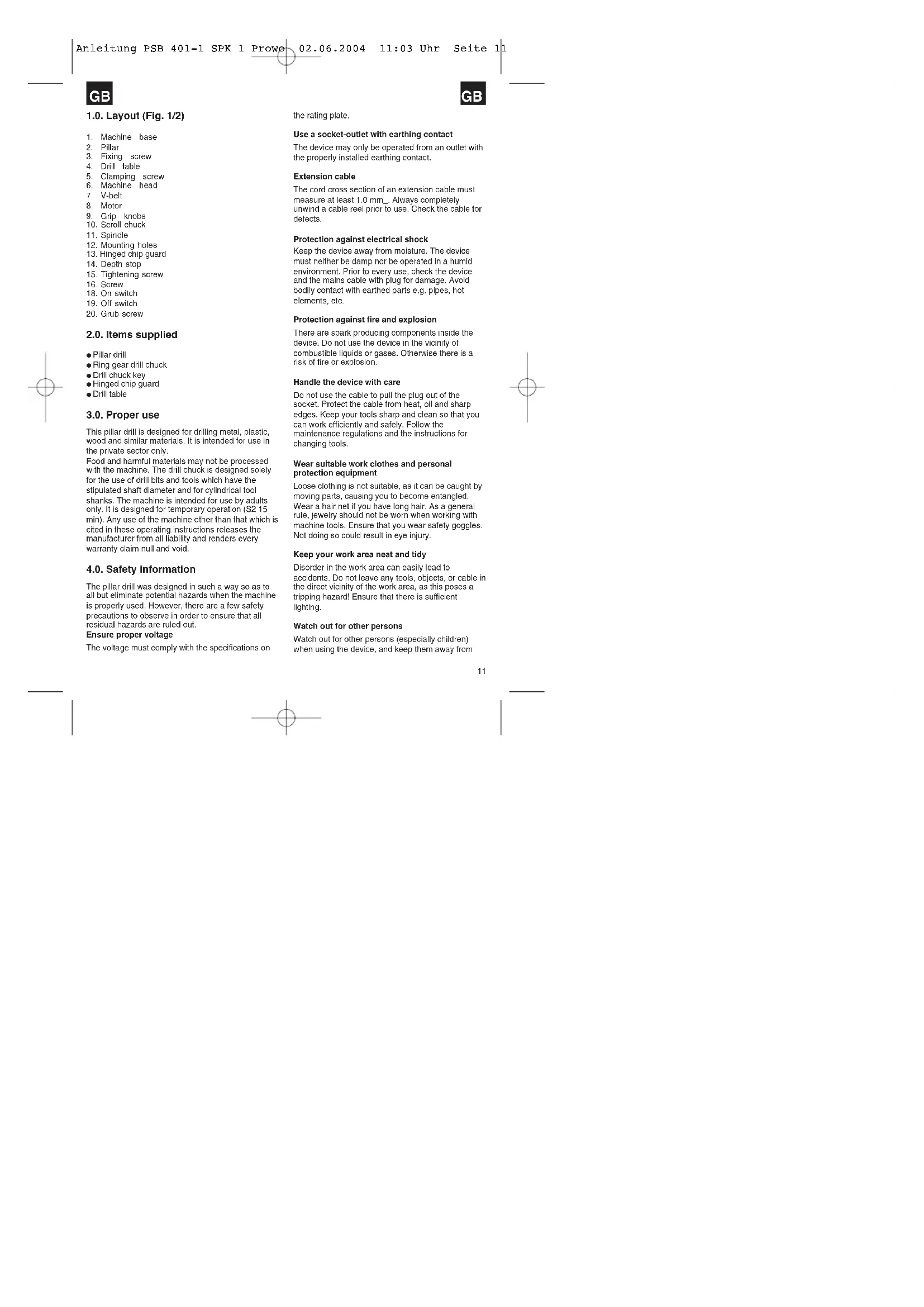
1.0. Layout (Fig. 1/2)
-
Machine base
-
Pillar
-
Fixing screw
-
Drill table
-
Clamping screw
-
Machine head
7 V-belt
8 Motor
9 Grin knobs
10 Scroll chuck
11 Spindle
12 Mounting holes
-
Hinged chin guard
-
Death stop
-
Tightening screw
-
Tightening screw
-
Screw
-
On cut
-
Off switch
-
Off switch
-
Grub screw
2.0. Items supplied
- Pillar drill
● Ring gear drill chuck
- Drill chuck key
● Hinged chip guard
- Drill table
3.0. Proper use
This pillar drill is designed for drilling metal, plastic, wood and similar materials. It is intended for use in the private sector only.
Food and harmful materials may not be processed with the machine. The drill chuck is designed solely for the use of drill bits and tools which have the stipulated shaft diameter and for cylindrical tool shanks. The machine is intended for use by adults only. It is designed for temporary operation (S2 15 min). Any use of the machine other than that which is cited in these operating instructions releases the manufacturer from all liability and renders every warranty claim null and void.
4.0. Safety information
The pillar drill was designed in such a way so as to all but eliminate potential hazards when the machine is properly used. However, there are a few safety precautions to observe in order to ensure that all residual hazards are ruled out.
Ensure proper voltage
The voltage must comply with the specifications on
the rating plate.
Use a socket-outlet with earthing contact
The device may only be operated from an outlet with the properly installed earthing contact.
Extension cable
The cord cross section of an extension cable must measure at least 1.0 mm. Always completely unwind a cable reel prior to use. Check the cable for defects.
Protection against electrical shock
Keep the device away from moisture. The device must neither be damp nor be operated in a humid environment. Prior to every use, check the device and the mains cable with plug for damage. Avoid bodily contact with earthed parts e.g. pipes, hot elements, etc.
Protection against fire and explosion
There are spark producing components inside the device. Do not use the device in the vicinity of combustible liquids or gases. Otherwise there is a risk of fire or explosion.
Handle the device with care
Do not use the cable to pull the plug out of the socket. Protect the cable from heat, oil and sharp edges. Keep your tools sharp and clean so that you can work efficiently and safely. Follow the maintenance regulations and the instructions for changing tools.
Wear suitable work clothes and personal protection equipment
Loose clothing is not suitable, as it can be caught by moving parts, causing you to become entangled. Wear a hair net if you have long hair. As a general rule, jewelry should not be worn when working with machine tools. Ensure that you wear safety goggles. Not doing so could result in eye injury.
Keep your work area neat and tidy
Disorder in the work area can easily lead to accidents. Do not leave any tools, objects, or cable in the direct vicinity of the work area, as this poses a tripping hazard! Ensure that there is sufficient lighting.
Watch out for other persons
Watch out for other persons (especially children) when using the device, and keep them away from
GB

GB
your work area. Do not let anyone touch the device or the power cable.
Store the tools in a safe location
Store unused devices in a dry, locked location that is out of the reach of children.
Avoid overloading the device
Operate the device only within the specified output range. Do not use any low-powered machines for heavy duty work. Do not use tools to perform work for which they were not intended.
Maintain a steady foothold
Ensure that you maintain a steady foothold while working. Avoid abnormal body positions and always keep your balance.
Pull out the mains plug
Pull out the mains plug when not using the tool, prior to maintenance, and when changing the drill bit.
Avoid unintentional start-up
Ensure that switch is turned off when plugging the plug into the socket.
Keep an eye on your work
Always keep an eye on your machine and the object you are working on. Never use the machine when you are not concentrating or are distracted. Never use the machine when you are under the influence of alcohol or are taking medication.
Check the tool for damage
Before using the tool, safety devices and any slightly damaged parts must be carefully checked to ensure that they are in good working order. Visually examine the tool's power cable on a regular basis. All parts must be correctly assembled and meet all the conditions required to ensure proper operation. Unless otherwise specified in the operating instructions, any damaged safety devices and parts must be properly repaired or replaced by a professionally recognized workshop. Never use tools with defective On/Off switches.
Warning! Using any plug-in tools and accessories other than those specified in these operating instructions can lead to injury.
Maximum workpiece size
Workpieces (max. 20 x 20 cm) may only be processed if they can be clamped securely on the drill table or in the vise.
Now, please read and follow all steps and procedures included in the operating instructions.
5.0. Technical data
SB 401/1
| Nominal input voltage 230V -/50 Hz | |
| Power rating 350 W | |
| Operating mode S2 15 min. | |
| Motor speed 1400 mln-1 | |
| Output speed 580 – 2.650 min-1 | |
| Speed levels 5 | |
| Drill chuck mount B 16 | |
| Scroll chuck ∅ 1.5 - 13 mm | |
| Max. shaft diameter 13 mm | |
| Throat | 104 |
| Drill depth 50 mm | |
| Pillar diameter 46 mm | |
| Height | 590 |
| Weight 18 kg | |
| LPA sound pressure level in idle mode | |
| 61,5 dB(A) |
| LWA sound power level in idle mode |
| 74,5 dB(A) |
Technical and visual enhancements may be made without prior notice. All dimensions, notes and specifications contained in these operating instructions are therefore subject to change.
Hand/am vibration is typically less than 2.5 m/s ^2 . Noise and vibration were determined in accordance with EN 61029-1 requirements.
6.0. Set-up
6.1. Assembly (Fig. 3)
Assemble the machine as follows:
- Position the machine base (1).
- Fasten the mounting flange with pillar (2) to machine base (1) using three screws (3) and washers.
● Push the drill table (4) with drill table clamp shaft onto the pillar (2) (Fig. 4). - Lock the drill table into the desired position using the clamping screw (5).
- Place the drill head (6) with V-belt cover (7) and motor (8) onto the drill pillar and fasten using the grub screw (20).
- Screw the three ball-shaped handles (9) onto the feeder cross handle.
Note: All bare parts are greased in order to protect them from corrosion. Before mounting the drill chuck
GB
(10) onto the spindle (11), both parts must be completely degreased using an environmentally friendly solvent. This ensures optimal transmission of power.
● Mount the drill chuck onto the spindle.
6.2. Installing the machine
Before the drill is started for the first time, it must be solidly and fully mounted on the work area of a stable workbench. Use both mounting holes (12) in the base plate to do this. Ensure that the machine is freely accessible for operation, adjustment and maintenance.
Note: The fixing screws may only be tightened to a point where they do not distort or deform the base plate. Excessive tension can lead to fracture.
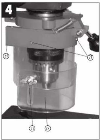
6.3. Hinged chip guard (Fig. 4)
Unscrew the three recessed head screws (21).
Push the transparent cover (23) into the groove of the red mounting frame (24) and fasten it again with the recessed head screws (21).
The height of the cover (23) is infinitely adjustable and can be locked using the two thumb screws (22). The chip guard (13) can be flipped upwards to change drill bits; ensure, however, that the chip guard (13) is back in its initial position before restarting the machine.
6.4. Prior to starting
Ensure that the voltage of the mains supply complies with the specifications on the rating plate. Connect the machine only to a socket with the properly installed earthing contact.
The table drill is equipped with a no-volt trip that is designed to protect the operator from an undesired restart following a drop in voltage. Should this occur, the machine must be manually restarted.
7.0. Operation

Wear suitable, protective clothing (i.e. rugged and tight-fitting) when working with the table drill.

Always wear safety goggles!

Long hair should always be bound back with a hair net or a cap!
GB
7.1. General (Fig. 2)
To switch on the machine, push in the green On button "l" (18); the machine starts up. To switch off, press the red Off button "O" (19); the device shuts down. Ensure that you do not overload the device. If the sound of the motor drops in pitch during operation, it is being overloaded. Do not overload the device to the point where the motor comes to a standstill.
The machine is designed for continuous operation with intermittent load (S2 15 min.).
The machine may be operated under a full load for a maximum of 15 minutes, at which time the machine needs to idle for 15 minutes. This prevents the motor from overheating.
7.2. Inserting the tool (Fig. 1)
Make sure that the power plug is removed from the socket-outlet before changing tools. Only cylindrical tools with the stipulated maximum shaft diameter may be clamped in the scroll chuck (10). Only use a tool that is sharp and free of defects. Do not use tools whose shaft is damaged or which are deformed or flawed in any other way. Use only accessories and attachments that are specified in the operating instructions or have been approved by the manufacturer.
7.3. Handling the drill chuck (Fig. 1)
Your table drill is equipped with a scroll chuck (10). In order to insert a drill bit, flip up the chip guard (13), insert the drill bit, then tighten down the drill chuck using the supplied chuck key. Pull out the chuck key. Ensure that the clamped in tool is firmly seated.
Caution! Do not leave the chuck key in the clamp hole.
Doing so will cause it to shoot out, which could cause injury.
7.4. Setting the speed (Fig. 1/6/7)
First switch the machine off, then pull out the mains plug.
The various spindle speeds can be set by moving the V-belt.
Proceed as follows:
- Remove the screw (16) in order to open the V-belt cover (7).
- Slacken the tightening screw (15) and push the motor (8) in the direction of the machine head.
- Move the V-belt to the desired position.
- Refer to the table for the recommended speeds for different drill bit materials (Fig. 6).
● Tighten the V-belt by pushing the motor (8) back from the machine head (6). Screw the tightening

GB
screw (16) back down again. The tension is properly set when the V-belt flexes in the middle by approx. 1 cm when pressed.
- Close the V-belt cover and screw down using the screw (16).
The V-belt cover (7) must always be locked tight, as the machine is equipped with a safety switch that only allows the machine to be turned on when the V-belt cover (7) is closed.
Caution! Never let the pillar drill run when the V-belt cover is open. Always pull the mains plug before opening the cover. Never touch the V-belt when it is rotating.
7.5 Drill depth stop (Fig. 8)
The drill depth can be set exactly by means of the depth stop (14) and a scale (a) on the front side of the machine head. The machine must be switched off in order to set the depth stop.
- Insert the required bit (7.2) and turn the setting screws up.
- Using the handle, move the bit so that its tip just touches the surface of the workpiece and read the value indicated on the scale.
- Remove the workpiece.
- Add the required drill depth to the value you read off the scale and use the handle to lower the bit until the value you calculated is indicated on the scale.
- Turn down the lower setting screw as far as it will go.
- Secure the setting by turning the upper setting screw against the lower setting screw.
Important! When setting the drill depth of a cylindrical hole you must add the length of the drill tip
7.6. Setting the angle of the drill table (Fig. 6)
- Slacken the carriage bolt (26) under the drill table (4).
- Set the drill table (4) to the desired angle (which can be read off the scale on the top side of the drill table).
● Tighten down the carriage bolt (26) in order to lock the drill table (4) into this position.
7.7. Setting the height of the drill table (Fig. 1/2)
- Slacken the tightening screw (5).
- Set the drill table (4) to the desired height by pressing down or lifting up and simultaneously (gently) pushing to the left or right.
● Screw the tightening screw (5) back down again.
7.8. Locking the workpiece into position (Fig. 1)
As a general rule, use a machine vice (14) or another
GB
suitable clamping device to lock a workpiece into position.
Never hold the workpiece in place with your hand!
When drilling, the workpiece should be able to travel on the drill table (4) for self-centering purposes. Ensure that the workpiece cannot rotate. This is best achieved by placing the workpiece/machine vice on a sturdy block.
Caution! Sheet metal parts must be clamped in to prevent them from being torn up. Properly set the height and angle of the drill table for each workpiece. There must be enough distance between the upper edge of the workpiece and the tip of the drill bit.
7.9. Drilling wood
Please note that sawdust must be properly evacuated when working with wood, as it can pose a health hazard. Ensure that you wear a suitable dust mask when performing work that generates dust.
7.10. Working speeds
Ensure that you drill at the proper speed. Drill speed is dependent on the diameter of the drill bit and the material in question.
The table below acts as a guide for selecting the proper speed for various materials.
Note: The drill speeds specified are merely suggested values.
| Drill bit ∅ Cast iron Steel Iron Aluminium Bronze |
| 3 2550 1600 2230 9500 8000 |
| 4 1900 1200 1680 7200 8000 |
| 5 1530 955 1340 5700 4800 |
| 6 1270 800 1100 4800 4000 |
| 7 1090 680 960 4100 3400 |
| 8 960 600 840 3600 3000 |
| 9 850 530 740 3200 2650 |
| 10 785 480 670 2800 2400 |
| 11 700 435 610 2800 2170 |
| 12 640 400 560 2400 2000 |
| 13 590 370 515 2200 1840 |
| 14 545 340 480 2000 1700 |
| 16 480 300 420 1800 1500 |
| 18 425 265 370 1800 1300 |
| 20 380 240 335 1400 1200 |
| 22 350 220 305 1300 1100 |
| 25 305 190 270 1150 950 |
GB
7.11. Countersinking and center-drilling
With this table drill, you can also countersink and center-drill. Please observe that countersinking should be performed at the lowest speed, while a high speed is required for center-drilling.
8.0. Care and maintenance
The table drill is to a large extent maintenance-free.
Keep the device clean. Pull out the mains plug before doing any cleaning and maintenance work on the machine.
Do not use any harsh, abrasive cleaning solvents. Ensure that no liquid seeps into the device.
Regrease all bare parts when the work is finished.
The drill pillar, blank parts of the column, and the drill table especially should be regreased at regular intervals. Use a standard, acid-free lubricating grease to do this.
Caution: Do not use your household refuse bin as a receptacle for oil and grease-soaked cleaning rags or grease and oil sludge. Dispose of these toxic materials in an environmentally-friendly fashion.
Regularly check and clean the ventilation holes. Store the device in a dry room. Should the device become damaged, do not try to repair it yourself; leave this work to the hands of a qualified electrical technician.
9.0. Ordering replacement parts
Replacement parts can be ordered through ISC GmbH (see the warranty declaration for the address). The following information should be provided when placing an order:
● Model/type of device
- Item number of device
● I.D. number of device
● Number of the required replacement part
GB

F
The image is too blurry to recognize any text content.
The image is too blurry to recognize any text content.
7.5 Boredybdestop (fig. 8)
text_image
Labeled diagram of a drill press machine with numbered parts for identification© EG Konformitätserklärung
GB EC Declaration of Conformity
F Déclaration de Conformité CE
NL EC Conformiteitsverklaring
E Declaracion CE de Conformidad
P Declaração de conformidade CE
⑤ EC Konformitetsförklaring
FIN EC Yhdenmukaisuusilmoitus
N EC Konfirmitetserklæring
EC Заявление о конформности
HR Dichiarazione di conformità CE
RO Declaratie de conformitate CE
TR ATUygunluk Deklarasyonu
The undersigned declares in the name of the company that the product is in compliance with the following guidelines and standards.
The image contains a single, solid horizontal line, which is a stylistic or background element (like a rule line on paper). According to Rule 2, such lines must be ignored by the OCR result. Therefore, the corrected OCR text is:
[Empty]
97/23/EG
The image contains no text or characters.
R&TTED 1999/5/EG
×
89/336/EWG
□
2000/14/EG: L_WM dB(A); L_VA dB(A)
The image contains no text or characters.
90/396/EWG
EN 61029-1; EN 55014-1; EN 55014-2; EN 61000-3-2; EN 61000-3-3
Eschenstraße 6 · D-94405 Landau/Isar (Germany)
Info-Tel. 0180-5 120 509 • Telefax 0180-5 835 830
(2) Date: 2019.03.08 at 10:00 a.m. Tuesday
GRI
The reprinting or reproduction by any other means, in whole or in
part, of documentation and papers accompanying pro
permitted only with the express consent of B2C GmbH
F
Institutional development of the SIC GmbH
①
7). Technical changes subject to change
- Technical changes subject to
① Sous reserve de modifications
(2) Portfolio Shoring for Delivered
The product described in these instructions comes with a 2-year warranty covering defects. This 2-year warranty period begins with the passing of risk or when the customer receives the product.
For warranty claims to be accepted, the product has to receive the current maintenance and be put to the proper use as described in the operating instructions.
Your statutory rights of warranty are naturally unaffected during these 2
This warranty applies in Germany, or in the respective country of the manufacturer's main regional sales partner, as a supplement to local regulations. Please note the details for contacting the customer service center responsible for your region or the service address listed below.
NL GARANTIE
© Einbell Portugal Ltda
Acartado 2100
Eua na Akieja. 225 Apartado 2100
R-4405-017 Arcozelo VNG
Tel. 022 0917500 Fax 022 0917529
① Einhell itela s.r.l.
Via Marconi 16
L22070 Berenazzo (Co)
Tel: 031 992080 Fax: 031 992084
DK Einbell Skendinovia
Erlmell Skandina
Bergesbesty, 3d.
DK-8600 Silkeborg Tel. 087 201200, Fax 087 201203
⑤ Haren Haralrison
Barlastrualer 3
S-41463 Gateburg
① Fickell Motors AG
Positooks 2005 N-3255 Lapik
(1) Sibhālwa, Hainu QX
Kopamonkefu 2
FIN. 23840
Tel. 03 2345000, Fax 03 2345040
PL Einbell Polska sp. 7.0.0
UL Miedzyleska 2-5
PL-50-514 Wroclaw
Tel. 071 3346508, Fax 071 3346503
(H) Finbell Hungary Ltd
Vaida Peter v. 12
H-1069 Budapest
Tel. 01 3039401, Fax 01 2101179
TR Semak
mekins ticaret ve sanavl ltd. stl.
Alay Cesme mah Yasemin Sok. No: 19
TB 34843 Maltene - Istenbul
Tel. 0216 4594905 Fax 0216 4429325
Vobler s.r.o
Zuρηλ 4
SK-95301 Zlate Morayce
Tel. 37 6426255, Fax 37 26256
K2 Turkestan
© An. Mayrolidopoulos S.A.
Technical & Commercial Company
- Papastratou & Asklipiou Str
GR 18545 Piritus
Tel 0210 4136155, Fax 0210 4137692
(16) Berman
Altufveurskon sbasse 24
BUS-127273 Moscow
Tel 095 7870179. Fax 095 5401750
Dibita
Motoio, 67
Metalo str. 23 LT-02180 Yinplus
Tel 05 2395709 Fax 05 2395770
(5) AS Baltail
Bouley
Haaslava vald
FF-52102 Tart
Tel 07 301 700. Fax 07 301 701
Helai Trading Co. LLC
POB 9282, Nakheel Rd, Delra. Shop No. 15
UAE-Dubai
Tel. 04 2279554, Fax 04 2217696
(1) Alborz Abzar Co. Ltd.
No. 111, Bestan Passage, Imam Khomeini Ave.
IR-11146 Teheran
Tel 021 6716072.
⑩ FISdop
Poslovni Center 96
BA-87000 Vitez
Tel 030 715 267, Fax 030 715 320
CS HANIMEX 400
Uzicke republike 50
SCG-31000 Uzice
Tel: 031 551 593, Fax: 031 601 538
② Eurasia Industrial and Automotive Supply
Bosseper Sir
Duncanville
ZA-Vereeniging 1930
Tel 16 455 571 2, Fax 16 455 571 6
EH 04:2004