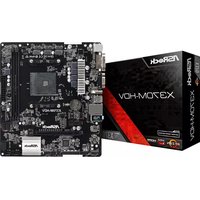
AM1B-ITX - Motherboard ASROCK - Free user manual and instructions
Find the device manual for free AM1B-ITX ASROCK in PDF.
Download the instructions for your Motherboard in PDF format for free! Find your manual AM1B-ITX - ASROCK and take your electronic device back in hand. On this page are published all the documents necessary for the use of your device. AM1B-ITX by ASROCK.
USER MANUAL AM1B-ITX ASROCK
Version 1.1 Published May 2016 Copyright©2016 ASRock INC. All rights reserved. Copyright Notice: No part of this documentation may be reproduced, transcribed, transmitted, or translated in any language, in any form or by any means, except duplication of documentation by the purchaser for backup purpose, without written consent of ASRock Inc. Products and corporate names appearing in this documentation may or may not be registered trademarks or copyrights of their respective companies, and are used only for identication or explanation and to the owners’ benet, without intent to infringe. Disclaimer: Specications and information contained in this documentation are furnished for informational use only and subject to change without notice, and should not be constructed as a commitment by ASRock. ASRock assumes no responsibility for any errors or omissions that may appear in this documentation. With respect to the contents of this documentation, ASRock does not provide warranty of any kind, either expressed or implied, including but not limited to the implied warranties or conditions of merchantability or tness for a particular purpose. In no event shall ASRock, its directors, ocers, employees, or agents be liable for any indirect, special, incidental, or consequential damages (including damages for loss of prots, loss of business, loss of data, interruption of business and the like), even if ASRock has been advised of the possibility of such damages arising from any defect or error in the documentation or product. is device complies with Part 15 of the FCC Rules. Operation is subject to the following two conditions: (1) this device may not cause harmful interference, and (2) this device must accept any interference received, including interference that may cause undesired operation.
CALIFORNIA, USA ONLY
e Lithium battery adopted on this motherboard contains Perchlorate, a toxic substance controlled in Perchlorate Best Management Practices (BMP) regulations passed by the California Legislature. When you discard the Lithium battery in California, USA, please follow the related regulations in advance. “Perchlorate Material-special handling may apply, see www.dtsc.ca.gov/hazardouswaste/perchlorate” ASRock Website: http://www.asrock.comAUSTRALIA ONLY Our goods come with guarantees that cannot be excluded under the Australian Consumer Law. You are entitled to a replacement or refund for a major failure and compensation for any other reasonably foreseeable loss or damage caused by our goods. You are also entitled to have the goods repaired or replaced if the goods fail to be of acceptable quality and the failure does not amount to a major failure. If you require assistance please call ASRock Tel : +886-2-28965588 ext.123 (Standard International call charges apply) e terms HDMI™ and HDMI High-Denition Multimedia Interface, and the HDMI logo are trademarks or registered trademarks of HDMI Licensing LLC in the United States and other countries.1 English AM1B-ITX Motherboard Layout AM1B-ITX RoHS CMOS BATTERY 32Mb BIOS ATXPWR1 FSB800 DDR3_A1 (64 bit, 240-pin module) DDR3_A2 (64 bit, 240-pin module) SATA3 _1 Super I/O LAN AUDI O CODE C
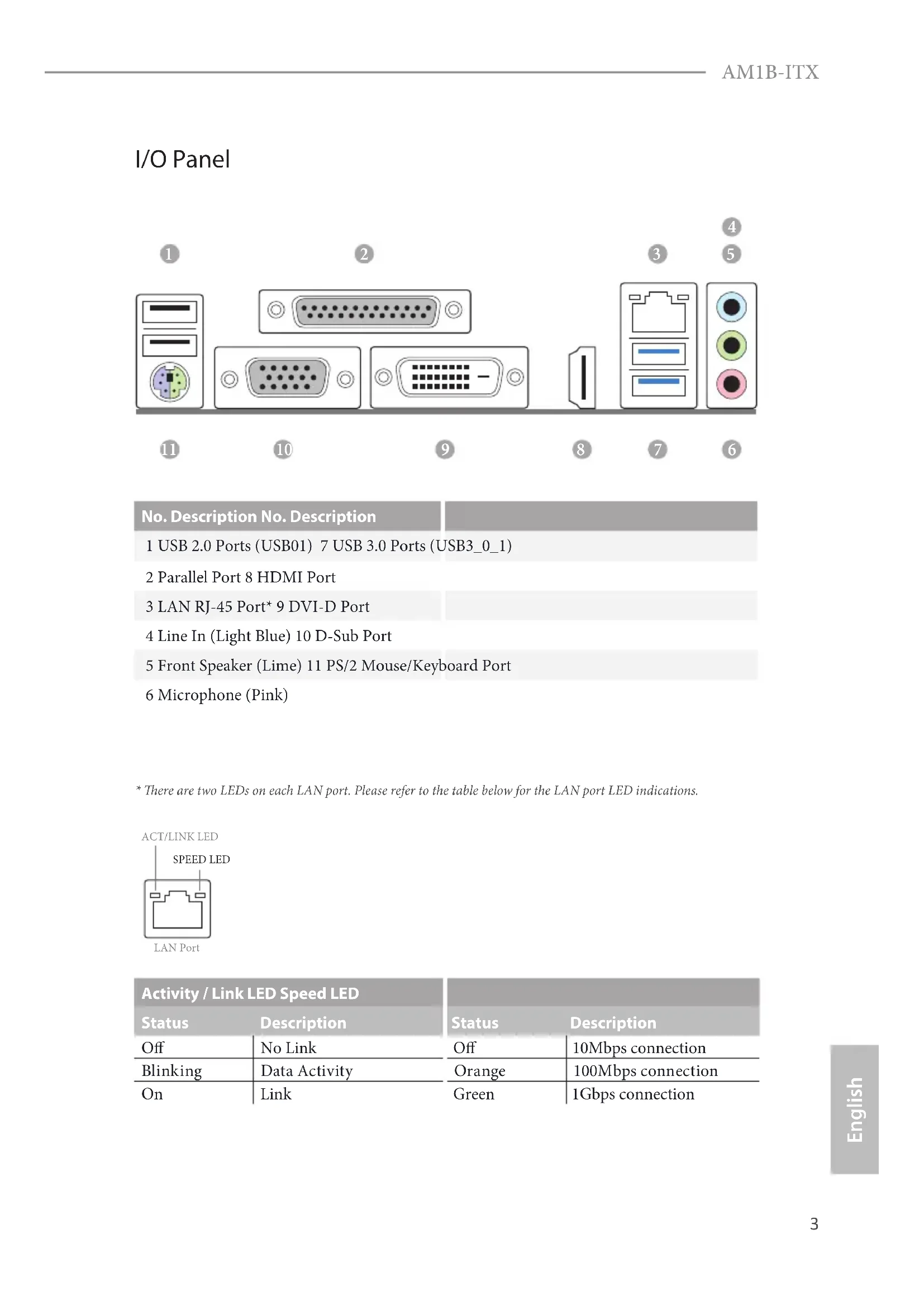
- ere are two LEDs on each LAN port. Please refer to the table below for the LAN port LED indications. Activity / Link LED Speed LED Status Description Status Description O No Link O 10Mbps connection Blinking Data Activity Orange 100Mbps connection On Link Green 1Gbps connection ACT/LINK LEDSPEED LEDLAN Port
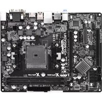
ank you for purchasing ASRock AM1B-ITX motherboard, a reliable motherboard produced under ASRock’s consistently stringent quality control. It delivers excellent performance with robust design conforming to ASRock’s commitment to quality and endurance.
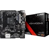
ASRock AM1B-ITX Support CD
1 x I/O Panel Shield Because the motherboard specications and the BIOS soware might be updated, the content of this documentation will be subject to change without notice. In case any modications of this documentation occur, the updated version will be available on ASRock’s website without further notice. If you require technical support related to this motherboard, please visit our website for specic information about the model you are using. You may nd the latest VGA cards and CPU support list on ASRock’s website as well. ASRock website http://www.asrock.com.5 English AM1B-ITX
All Solid Capacitor design CPU
Supports AMD AM1 Socket A-series and E-series Quad- Core/Dual-Core APU up to 25W Memory
Supports DDR3 1600/1333/1066 non-ECC, un-buered memory
Max. capacity of system memory: 32GB (see CAUTION1) Expansion Slot
Integrated AMD Radeon
R3 Series Graphics in A-series / E-series APU
Max. shared memory 2GB
Supports HDMI with max. resolution up to 4K × 2K (4096x2160) @ 24Hz or 4K × 2K (3840x2160) @ 30Hz
Supports DVI-D with max. resolution up to 1920x1200 @ 60Hz
Supports D-Sub with max. resolution up to 2048x1536 @ 60Hz
Supports Auto Lip Sync, Deep Color (12bpc), xvYCC and HBR (High Bit Rate Audio) with HDMI Port (Compliant HDMI monitor is required)
Supports HDCP with DVI-D and HDMI Ports
Supports Full HD 1080p Blu-ray (BD) playback with DVI-D and HDMI Ports Audio
Supports Full Spike Protection6 English LAN
Supports Wake-On-LAN
Supports Full Spike Protection
Supports LAN Cable Detection
Supports Energy Ecient Ethernet 802.3az
Supports PXE Rear Panel I/O
1 x Parallel Port (ECP/EPP support)
2 x USB 2.0 Ports (Supports Full Spike Protection)
2 x USB 3.0 Ports (Supports Full Spike Protection)
1 x RJ-45 LAN Port with LED (ACT/LINK LED and SPEED LED)
HD Audio Jacks: Line in / Front Speaker / Microphone Storage
2 x SATA3 6.0 Gb/s Connectors by AMD AM1 Series Socket 25W Quad-Core APU, support NCQ, AHCI and Hot Plug
2 x SATA3 6.0 Gb/s Connectors by ASMedia ASM1061, sup- port NCQ, AHCI and Hot Plug Connector
1 x CPU Fan Connector (4-pin)
1 x Power Fan Connector (3-pin)
1 x Front Panel Audio Connector
2 x USB 2.0 Headers (Support 4 USB 2.0 ports) (Supports Full Spike Protection)
1 x USB 3.0 Header by ASMedia ASM1042A (Supports 2 USB
3.0 ports) (Supports Full Spike Protection)7
English AM1B-ITX BIOS Feature
32Mb AMI UEFI Legal BIOS with GUI support
Supports “Plug and Play”
ACPI 1.1 compliance wake up events
DRAM Voltage multi-adjustment Support
Drivers, Utilities, AntiVirus Soware (Trial Version), Google Chrome Browser and Toolbar, Start8 (30 days trial) Hardware Monitor
CPU/Chassis temperature sensing
CPU Fan multi-speed control
ErP/EuP ready (ErP/EuP ready power supply is required)
- For detailed product information, please visit our website: http://www.asrock.com8 English Please realize that there is a certain risk involved with overclocking, including adjust- ing the setting in the BIOS, applying Untied Overclocking Technology, or using third- party overclocking tools. Overclocking may aect your system’s stability, or even cause damage to the components and devices of your system. It should be done at your own risk and expense. We are not responsible for possible damage caused by overclocking. Due to the operating system limitation, the actual memory size may be less than 4GB for the reservation for system usage under Windows® 8 / 7 / XP. For Windows® 64-bit OS with 64-bit CPU, there is no such limitation. You can use ASRock XFast RAM to utilize the memory that Windows® cannot use.9 English AM1B-ITX
ASRock A-Tuning A-Tuning is ASRock’s multi purpose soware suite with a new interface, more new features and improved utilities, including XFast RAM, Dehumidier, Good Night LED, FAN-Tastic Tuning and a whole lot more. ASRock Instant Boot ASRock Instant Boot allows you to turn on your PC in just a few seconds, provides a much more ecient way to save energy, time, money, and improves system running speed for your system. It leverages the S3 and S4 ACPI features which normally enable the Sleep/Standby and Hibernation modes in Windows® to shorten boot up time. By calling S3 and S4 at specic timing during the shutdown and startup process, Instant Boot allows you to enter your Windows® desktop in a few seconds. ASRock Instant Flash ASRock Instant Flash is a BIOS ash utility embedded in Flash ROM. is conve- nient BIOS update tool allows you to update the system BIOS in a few clicks without preparing an additional oppy diskette or other complicated ash utility. Just save the new BIOS le to your USB storage and launch this tool by pressing <F6> or <F2> during POST to enter the BIOS setup menu to access ASRock Instant Flash. Please be noted that the USB ash drive or hard drive must use FAT32/16/12 le system. ASRock APP Charger Simply by installing the ASRock APP Charger makes your iPhone/iPad/iPod Touch charge up to 40% faster than before on your computer. ASRock APP Charger allows you to quickly charge many Apple devices simultaneously and even supports continuous charging when your PC enters into Suspend to RAM (S3), hibernation mode (S4) or power o (S5). ASRock XFast LAN ASRock XFast LAN provides faster internet access, which includes the benets listed below. LAN Application Prioritization: You can congure your application’s priority ideally and add new programs to the list. Lower Latency in Game: Aer setting online game’s priority higher, it can lower the latency in games. Trac Shaping: You can watch Youtube HD videos and download simultaneously. Real- Time Analysis of Your Data: With the status window, you can easily recognize which data streams you are currently transferring.10 English ASRock XFast RAM ASRock XFast RAM is included in A-Tuning. It fully utilizes the memory space that cannot be used under Windows® 32-bit operating systems. ASRock XFast RAM shortens the loading time of previously visited websites, making web surng faster than ever. And it also boosts the speed of Adobe Photoshop 5 times faster. Another advantage of ASRock XFast RAM is that it reduces the frequency of accessing your SSDs or HDDs in order to extend their lifespan. ASRock Crashless BIOS ASRock Crashless BIOS allows users to update their BIOS without fear of failing. If power loss occurs during the BIOS updating process, ASRock Crashless BIOS will automatically nish the BIOS update procedure aer regaining power. Please note that BIOS les need to be placed in the root directory of your USB disk. Only USB 2.0 ports support this feature. ASRock OMG (Online Management Guard) Administrators are able to establish an internet curfew or restrict internet access at specied times via OMG. You may schedule the starting and ending hours of internet access granted to other users. In order to prevent users from bypassing OMG, guest accounts without permission to modify the system time are required. ASRock Internet Flash ASRock Internet Flash downloads and updates the latest UEFI rmware version from our servers for you without entering Windows
OS. Please setup network conguration before using Internet Flash. ASRock UEFI Tech Service Contact ASRock Tech Service by sending a support request from the UEFI setup utility if you are having trouble with your personal computer. Users may try to choose the category of the issue they have encountered, describe the problem in detail, and then attach an optional picture or log le for our technical support team. ASRock Dehumidier Function Users may prevent motherboard damages due to dampness by enabling “Dehumidier Function”. When enabling Dehumidier Function, the computer will power on automatically to dehumidify the system aer entering S4/S5 state.11 English AM1B-ITX ASRock Easy Driver Installer For users that don’t have an optical disk drive to install the drivers from our support CD, Easy Driver Installer is a handy tool in the UEFI that installs the LAN driver to your system via an USB storage device, then downloads and installs the other required drivers automatically. ASRock Interactive UEFI ASRock Interactive UEFI is a blend of system conguration tools, cool sound eects and stunning visuals. e unprecedented UEFI provides a more attractive interface and more amusment. ASRock Fast Boot With ASRock’s exclusive Fast Boot technology, it takes less than 1.5 seconds to logon to Windows 8 from a cold boot. No more waiting! e speedy boot will completely change your user experience and behavior. ASRock Restart to UEFI Windows® 8 brings the ultimate boot up experience. e lightning boot up speed makes it hard to access the UEFI setup. ASRock Restart to UEFI allows users to enter the UEFI automatically when turning on the PC. By enabling this function, the PC will enter the UEFI directly aer you restart. ASRock USB Key In a world where time is money, why waste precious time everyday typing usernames to log in to Windows? Why should we even bother memorizing those foot long passwords? Just plug in the USB Key and let your computer log in to windows automatically! ASRock FAN-Tastic Tuning ASRock FAN-Tastic Tuning is included in A-Tuning. Congure up to ve dierent fan speeds using the graph. e fans will automatically shi to the next speed level when the assigned temperature is met. ASRock Good Night LED ASRock Good Night LED technology oers you a better sleeping environment by extinguishing the unessential LEDs. By enabling Good Night LED in the BIOS, the Power/LAN LEDs will be switched o when the system is powered on. Good Night LED will automatically switch o the Power and LAN LEDs when the system enters into Standby/Hibernation mode as well.12 English
e illustration shows how jumpers are setup. When the jumper cap is placed on the pins, the jumper is “Short”. If no jumper cap is placed on the pins, the jumper is “Open”. e illustration shows a 3-pin jumper whose pin1 and pin2 are “Short” when a jumper cap is placed on these 2 pins. Clear CMOS Jumper (CLRCMOS1) (see p.1, No. 2) CLRCMOS1 allows you to clear the data in CMOS. To clear and reset the system parameters to default setup, please turn o the computer and unplug the power cord from the power supply. Aer waiting for 15 seconds, use a jumper cap to short pin2 and pin3 on CLRCMOS1 for 5 seconds. However, please do not clear the CMOS right aer you update the BIOS. If you need to clear the CMOS when you just nish updating the BIOS, you must boot up the system rst, and then shut it down before you do the clear-CMOS action. Please be noted that the password, date, time, and user default prole will be cleared only if the CMOS battery is removed. Clear CMOSDefault If you clear the CMOS, the case open may be detected. Please adjust the BIOS option “Clear Status” to clear the record of previous chassis intrusion status.13 English AM1B-ITX
1.5 Onboard Headers and Connectors
System Panel Header (9-pin PANEL1) (see p.1, No. 8) Connect the power switch, reset switch and system status indicator on the chassis to this header according to the pin assignments below. Note the positive and negative pins before connecting the cables. PWRBTN (Power Switch): Connect to the power switch on the chassis front panel. You may congure the way to turn o your system using the power switch. RESET (Reset Switch): Connect to the reset switch on the chassis front panel. Press the reset switch to restart the computer if the computer freezes and fails to perform a normal restart. PLED (System Power LED): Connect to the power status indicator on the chassis front panel. e LED is on when the system is operating. e LED keeps blinking when the system is in S3 sleep state. e LED is o when the system is in S4 sleep state or powered o (S5). HDLED (Hard Drive Activity LED): Connect to the hard drive activity LED on the chassis front panel. e LED is on when the hard drive is reading or writing data. e front panel design may dier by chassis. A front panel module mainly consists of power switch, reset switch, power LED, hard drive activity LED, speaker and etc. When connecting your chassis front panel module to this header, make sure the wire assignments and the pin assignments are matched correctly. Onboard headers and connectors are NOT jumpers. Do NOT place jumper caps over these headers and connectors. Placing jumper caps over the headers and connectors will cause permanent damage to the motherboard.14 English Serial ATA3 Connectors (SATA3_1: see p.1, No. 9) (SATA3_2: see p.1, No. 10) (SATA3_A1: see p.1, No. 12) (SATA3_A2: see p.1, No. 11) ese four SATA3 connectors support SATA data cables for internal storage devices with up to
6.0 Gb/s data transfer rate.
USB 2.0 Headers (9-pin USB4_5) (see p.1, No. 17) (9-pin USB6_7) (see p.1, No. 18) Besides two USB 2.0 ports on the I/O panel, there are two headers on this motherboard. Each USB
2.0 header can support
two ports. USB 3.0 Header (19-pin USB3_2_3) (see p.1, No. 14) Besides two USB 3.0 ports on the I/O panel, there is one header on this motherboard. is USB
3.0 header can support
two ports. Front Panel Audio Header (9-pin HD_AUDIO1) (see p.1, No. 19) is header is for connecting audio devices to the front audio panel. DUMMY GND GND
MIC_RETPRESENCE# GND OUT2_R MIC2_R MIC2_L OUT_RET15 English AM1B-ITX Chassis Speaker Header (4-pin SPEAKER1) (see p.1, No. 7) Please connect the chassis speaker to this header. Chassis and Power Fan Connectors (4-pin CHA_FAN1) (see p.1, No. 13) (3-pin PWR_FAN1) (see p.1, No. 1) Please connect fan cables to the fan connectors and match the black wire to the ground pin. CPU Fan Connector (4-pin CPU_FAN1) (see p.1, No. 3) is motherboard pro- vides a 4-Pin CPU fan (Quiet Fan) connector. If you plan to connect a 3-Pin CPU fan, please connect it to Pin 1-3. ATX Power Connector (24-pin ATXPWR1) (see p.1, No. 6) is motherboard pro- vides a 24-pin ATX power connector. To use a 20-pin ATX power supply, please plug it along Pin 1 and Pin
1. High Denition Audio supports Jack Sensing, but the panel wire on the chassis must
support HDA to function correctly. Please follow the instructions in our manual and chassis manual to install your system.
2. If you use an AC’97 audio panel, please install it to the front panel audio header by
the steps below: A. Connect Mic_IN (MIC) to MIC2_L. B. Connect Audio_R (RIN) to OUT2_R and Audio_L (LIN) to OUT2_L. C. Connect Ground (GND) to Ground (GND). D. MIC_RET and OUT_RET are for the HD audio panel only. You don’t need to connect them for the AC’97 audio panel. E. To activate the front mic, go to the “FrontMic” Tab in the Realtek Control panel and adjust “Recording Volume”.
English Serial Port Header (9-pin COM1) (see p.1, No. 16) is COM1 header supports a serial port module. Chassis Intrusion Header (2-pin CI1) (see p.1, No. 4) is motherboard supports CASE OPEN detection feature that detects if the chassis cove has been removed. is feature requires a chassis with chassis intrusion detection design. TPM Header (17-pin TPMS1) (see p.1, No. 15) is connector supports Trusted Platform Module (TPM) system, which can securely store keys, digital certicates, passwords, and data. A TPM system also helps enhance network security, protects digital identities, and ensures platform integrity.
ASRock AM1B-ITX-Support-CD
1 x Parallel Port (ECP/EPP Support)
Supporta Wake-On-LAN
Supporta Energy Ecient Ethernet 802.3az
Supporta “Plug and Play”
Soporta “jumper free setup”
- 1 x CPU 风扇接口 (4-pin)
Siap untuk ErP/EuP (memerlukan catu daya untuk ErP/EuP)Contact Information If you need to contact ASRock or want to know more about ASRock, you’re welcome to visit ASRock’s website at http://www.asrock.com; or you may contact your dealer for further information. For technical questions, please submit a support request form at http://www.asrock.com/support/tsd.asp ASRock Incorporation 2F., No.37, Sec. 2, Jhongyang S. Rd., Beitou District, Taipei City 112, Taiwan (R.O.C.) ASRock EUROPE B.V. Bijsterhuizen 11-11 6546 AR Nijmegen e Netherlands Phone: +31-24-345-44-33 Fax: +31-24-345-44-38 ASRock America, Inc. 13848 Magnolia Ave, Chino, CA91710 U.S.A. Phone: +1-909-590-8308 Fax: +1-909-590-1026EC-Declaration of Conformity For the following equipment: Motherboard (Product Name) AM1B-ITX / ASRock (Model Designation / Trade Name) ASRock Incorporation (Manufacturer Name) 2F., No.37, Sec. 2, Jhongyang S. Rd., Beitou District, Taipei City 112, Taiwan (R.O.C.) (Manufacturer Address) is herewith conrmed to comply with the requirements set out in the Council Directive on the Approximation of the Laws of the Member States relating to Electromagnetic Compatibility Directive (2004/108/EC) and Safety Directive (2006/95/ EC), the following standards are applied:
EN 55024: 1998 + A1:2001 + A2:2003 IEC 61000-4-2: 2008; IEC 61000-4-3: 2010; IEC 61000-4-4: 2010; IEC 61000-4-5: 2005; IEC 61000-4-6: 2008; IEC 61000-4-8: 2009; IEC 61000-4-11: 2004;
e following manufacturer / importer or authorized representative established within the EUT is responsible for this declaration: ASRock EUROPE B.V. (Company Name) Bijsterhuizen 1111 6546 AR Nijmegen e Netherlands (Company Address) Person responsible for making this declaration: (Name, Surname) A.V.P (Position / Title) Feb. 21, 2014 (Date) P/N: 15G06X717002AK V1.1