QC5000-ITX/WIFI - Motherboard ASROCK - Free user manual and instructions
Find the device manual for free QC5000-ITX/WIFI ASROCK in PDF.

User questions about QC5000-ITX/WIFI ASROCK
0 question about this device. Answer the ones you know or ask your own.
Ask a new question about this device
Download the instructions for your Motherboard in PDF format for free! Find your manual QC5000-ITX/WIFI - ASROCK and take your electronic device back in hand. On this page are published all the documents necessary for the use of your device. QC5000-ITX/WIFI by ASROCK.
USER MANUAL QC5000-ITX/WIFI ASROCK
Published October 2014
Copyright©2014 ASRock INC. All rights reserved.
Copyright Notice:
No part of this documentation may be reproduced, transcribed, transmitted, or translated in any language, in any form or by any means, except duplication of documentation by the purchaser for backup purpose, without written consent of ASRock Inc.
Products and corporate names appearing in this documentation may or may not be registered trademarks or copyrights of their respective companies, and are used only for identification or explanation and to the owners' benefit, without intent to infringe.
Disclaimer:
Specifications and information contained in this documentation are furnished for informational use only and subject to change without notice, and should not be constructed as a commitment by ASRock. ASRock assumes no responsibility for any errors or omissions that may appear in this documentation.
With respect to the contents of this documentation, ASRock does not provide warranty of any kind, either expressed or implied, including but not limited to the implied warranties or conditions of merchantability or fitness for a particular purpose.
In no event shall ASRock, its directors, officers, employees, or agents be liable for any indirect, special, incidental, or consequential damages (including damages for loss of profits, loss of business, loss of data, interruption of business and the like), even if ASRock has been advised of the possibility of such damages arising from any defect or error in the documentation or product.
The terms HDMI ^™ and HDMI High-Definition Multimedia Interface, and the HDMI logo are trademarks or registered trademarks of HDMI Licensing LLC in the United States and other countries.

This device complies with Part 15 of the FCC Rules. Operation is subject to the following two conditions:
(1) this device may not cause harmful interference, and
(2) this device must accept any interference received, including interference that may cause undesired operation.
CALIFORNIA, USA ONLY
The Lithium battery adopted on this motherboard contains Perchlorate, a toxic substance controlled in Perchlorate Best Management Practices (BMP) regulations passed by the California Legislature. When you discard the Lithium battery in California, USA, please follow the related regulations in advance.
"Perchlorate Material-special handling may apply, see www.dtsc.ca.gov/hazardouswaste/perchlorate"
ASRock Website: http://www.asrock.com
AUSTRALIA ONLY
Our goods come with guarantees that cannot be excluded under the Australian Consumer Law. You are entitled to a replacement or refund for a major failure and compensation for any other reasonably foreseeable loss or damage caused by our goods. You are also entitled to have the goods repaired or replaced if the goods fail to be of acceptable quality and the failure does not amount to a major failure. If you require assistance please call ASRock Tel: +886-2-28965588 ext.123 (Standard International call charges apply)
The terms HDMI ^™ and HDMI High-Definition Multimedia Interface, and the HDMI logo are trademarks or registered trademarks of HDMI Licensing LLC in the United States and other countries.

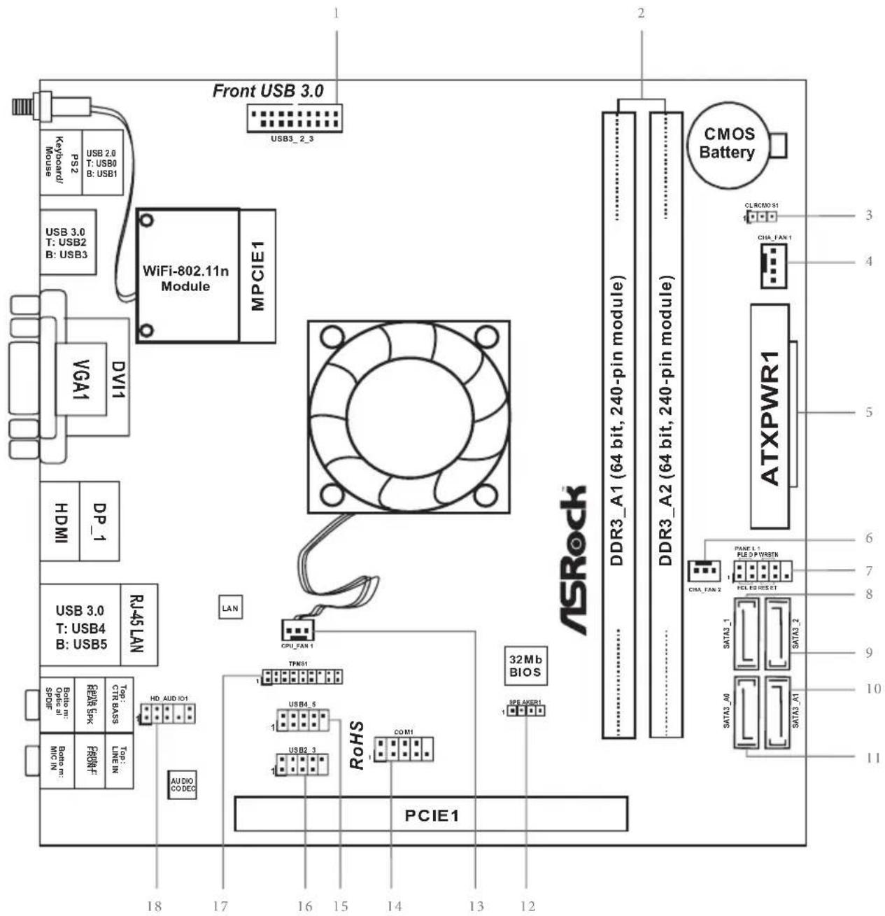
Motherboard Layout
text_image
18 17 16 15 14 13 12 1 2 3 4 5 6 7 8 9 10 11 12 13 14 15 16 17 18 R0HS PCIE1 CPU: 2.3 USB2_3 USB4_5 Top: 31A BASS Top: Optel pl SPIF Radio PSK Radio BPS Top: Line IN Top: USB4 B: USB5 USB3.0 T: USB4 B: USB5 HDMI DPI-1 RV45 LAN LAN TPMSI P20_PAN 1 32Mb BIOS ASRock™ DDR3_A1 (64 bit, 240-pin module) DDR3_A2 (64 bit, 240-pin module) ATXPWR1 CMOS Battery CIA_FAN 2 SATA3_A0 SATA3_1 SATA3_A1 SATA3_2 CIA_FAN 1 PUFP/VREFIN PWM1_1 PWM2_1 PWM3_1 PWM4_1 PWM5_1 PWM6_1 PWM7_1 PWM8_1 PWM9_1 PWM10_1 PWM11_1 PWM12_1 PWM13_1 PWM14_1 PWM15_1 PWM16_1 PWM17_1 PWM18_1 PWM19_1 PWM20_1 PWM21_1 PWM22_1 PWM23_1 PWM24_1 PWM25_1 PWM26_1 PWM27_1 PWM28_1 PWM29_1 PWM30_1 PWM31_1 PWM32_1 PWM33_1 PWM34_1 PWM35_1 PWM36_1 PWM37_1 PWM38_1 PWM39_1 PWM40_1 PWM41_1 PWM42_1 PWM43_1 PWM44_1 PWM45_1 PWM46_1 PWM47_1 PWM48_1 PWM49_1 PWM50_1 PWM51_1 PWM52_1 PWM53_1 PWM54_1 PWM55_1 PWM56_1 PWM57_1 PWM58_1 PWM59_1 PWM60_1 PWM61_1 PWM62_1 PWM63_1 PWM64_1 PWM65_1 PWM66_1 PWM67_1 PWM68_1 PWM69_1 PWM70_1 PWM71_1 PWM72_1 PWM73_1 PWM74_1 PWM75_1 PWM76_1 PWM77_1 PWM78_1 PWM79_1 PWM80_1 PWM81_1No. Description
| 1 USB 3.0 Header (USB3_2_3) |
| 2 2 x 240-pin DDR3 DIMM Slots (DDR3_A1, DDR3_A2) |
| 3 Clear CMOS Jumper (CLRCMOS1) |
| 4 Chassis Fan Connector (CHA_FAN1) |
| 5 ATX Power Connector (ATXPWR1) |
| 6 Chassis Fan Connector (CHA_FAN2) |
| 7 System Panel Header (PANEL1) |
| 8 SATA3 Connector (SATA3_1) |
| 9 SATA3 Connector (SATA3_2) |
| 10 SATA3 Connector (SATA3_A1) |
| 11 SATA3 Connector (SATA3_A0) |
| 12 Chassis Speaker Header (SPEAKER1) |
| 13 CPU Fan Connector (CPU_FAN1) |
| 14 COM Port Header (COM1) |
| 15 USB 2.0 Header (USB4_5) |
| 16 USB 2.0 Header (USB2_3) |
| 17 TPM Header (TPMS1) |
| 18 Front Panel Audio Header (HD_AUDIO1) |
* WiFi-802.11n Module and SMA Wi-Fi Antenna Cable are for QC5000-ITX/WiFi only.
* The fan on the CPU heatsink is for QC5000-ITX/WiFi / QC5000-ITX only.
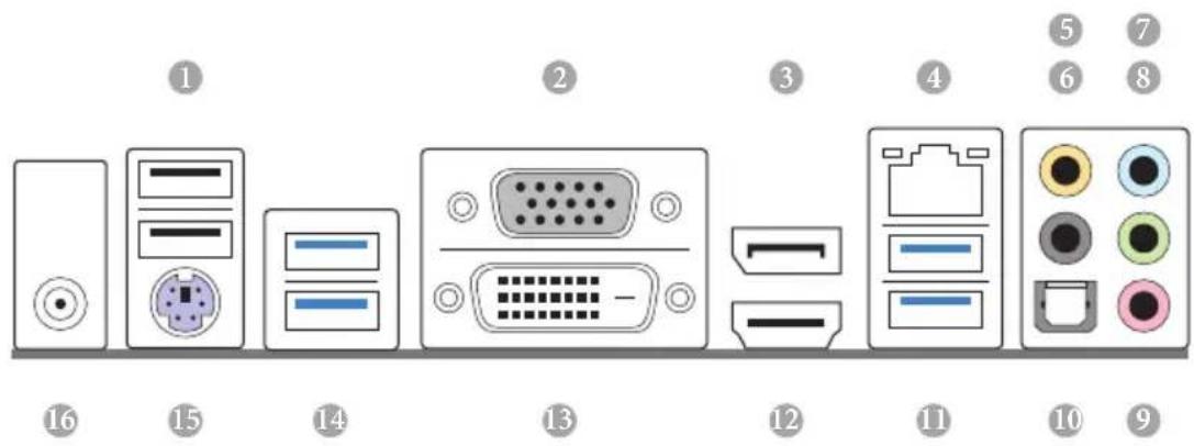
I/O Panel
text_image
1 2 3 4 5 6 7 8 9 10 11 12 13 14 15 16No. Description No. Description
1 USB 2.0 Ports (USB01) 9 Microphone (Pink)
2 D-Sub Port 10 Optical SPDIF Out Port
3 DisplayPort 1.2* 11 USB 3.0 Ports (USB3_4_5)
4 LAN RJ-45 Port** 12 HDMI Port*
5 Central / Bass (Orange) 13 DVI-D Port
6 Rear Speaker (Black) 14 USB 3.0 Ports (USB3_0_1)
7 Line In (Light Blue) 15 PS/2 Mouse/Keyboard Port
8 Front Speaker (Lime)***
16
Antenna Port (for QC5000-ITX/WiFi only)
* HDMI and DisplayPort 1.2 cannot output at the same time. You can only choose either one of them. Please refer to the BIOS setup option "HDMI/DP Switch" on page 43 of user manual in the support CD.
** There are two LEDs on each LAN port. Please refer to the table below for the LAN port LED indications.
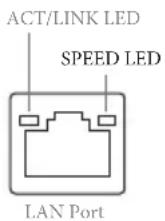
Activity / Link LED Speed LED Status Description Status Description
| Off No Link Off | 10Mbps connection | |
| Blinking Data Activity Orange 100Mbps connection | ||
| On Link Green 1 | Gbps connection | |
*** If you use a 2-channel speaker, please connect the speaker's plug into "Front Speaker Jack". See the table below for connection details in accordance with the type of speaker you use.
| Audio Output Channels | Front Speaker (No. 8) | Rear Speaker (No. 6) | Central / Bass (No. 5) | Line In or Side Speaker (No. 7) |
| 2 V -- -- -- | ||||
| 4 V V -- -- | ||||
| 6 V V V -- | ||||
| 8 V V V V |

To enable Multi-Streaming, you need to connect a front panel audio cable to the front panel audio header. After restarting your computer, you will find the "Mixer" tool on your system. Please select "Mixer ToolBox" click "Enable playback multi-streaming", and click "ok". Choose "2CH", "4CH", "6CH", or "8CH" and then you are allowed to select "Realtek HDA Primary output" to use the Rear Speaker, Central/Bass, and Front Speaker, or select "Realtek HDA Audio 2nd output" to use the front panel audio.
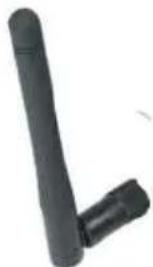
WiFi-802.11n Module and ASRock WiFi 2.4GHz Antenna (for QC5000-ITX/WiFi only)
WiFi-802.11n Module
WiFi-802.11n module is an easy-to-use wireless local area network (WLAN) adapter to support WiFi function. With WiFi-802.11n module, you can easily create a wireless environment and enjoy the convenience of wireless network connectivity. Therefore, from anywhere within the signal range, you will be able to play LAN games, connect to the internet, access and share printers, and make Internet phone calls easily.
natural_image
Black USB port terminal with a curved handle and a separate L-shaped tip (no text or symbols visible)ASRock WiFi 2.4GHz Antenna
Antenna Port
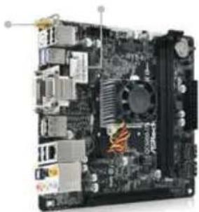
WiFi-802.11n Module
natural_image
Interior view of a computer motherboard showing CPU socket, RAM slots, and heatsink (no visible text or labels)WiFi-802.11n module supports Station mode. You can use the wireless function to connect the access point (AP), or connect with other stations in the wireless range instead. There are two choices provided in station mode: Infrastructure mode and Ad-hoc mode. Please read below introduction for the differences of these two modes.
Infrastructure Mode
If you have a present access point (AP) in your wireless network environment for this station to join, you can set up WiFi-802.11n module in Infrastructure mode. In this mode, WiFi-802.11n module acts as a wireless adapter. In other words, it is centered on an AP that provides Internet access and LAN communication for the wireless stations, such as PC, notebook and other devices.
Ad-hoc Mode
If you don't have a present access point in your wireless network environment, you can set up WiFi-802.11n module in Ad-hoc mode. The wireless network brings together workstations, PC, notebook and other devices for wireless communication.
Chapter 1 Introduction
Thank you for purchasing ASRock QC5000-ITX/WiFi / QC5000-ITX / QC5000-ITX/PH motherboard, a reliable motherboard produced under ASRock's consistently stringent quality control. It delivers excellent performance with robust design conforming to ASRock's commitment to quality and endurance.

Because the motherboard specifications and the BIOS software might be updated, the content of this documentation will be subject to change without notice. In case any modifications of this documentation occur, the updated version will be available on ASRock's website without further notice. If you require technical support related to this motherboard, please visit our website for specific information about the model you are using. You may find the latest VGA cards and CPU support list on ASRock's website as well. ASRock website http://www.asrock.com.
1.1 Package Contents
- ASRock QC5000-ITX/WiFi / QC5000-ITX / QC5000-ITX/PH Motherboard (Mini-ITX Form Factor)
- ASRock QC5000-ITX/WiFi / QC5000-ITX / QC5000-ITX/PH Quick Installation Guide
• ASRock QC5000-ITX/WiFi / QC5000-ITX / QC5000-ITX/PH Support CD
• 2 x Serial ATA (SATA) Data Cables (Optional) - 1 x I/O Panel Shield
• 1 x ASRock WiFi 2.4GHz Antenna (for QC5000-ITX/WiFi only) - 1 x WiFi Module Screw (for QC5000-ITX / QC5000-ITX/PH only)
1.2 Specifications
Platform
- Mini-ITX Form Factor
• All Solid Capacitor design
• High Density Glass Fabric PCB
CPU
• AMD FT3 Kabini A4-5000 Quad-Core APU
Memory
• 2 x DDR3 DIMM Slots
- Supports DDR3 1600/1333/1066 non-ECC, un-buffered memory
• Max. capacity of system memory: 16GB (see CAUTION1)
Expansion
• 1 x PCI Express 2.0 x16 Slot (PCIE1 @ x4 mode)
• 1 x Mini-PCI Express Slot: For WiFi Module
Graphics
- Integrated AMD Radeon ^TM HD 8330 Graphics
- DirectX 11.1, Pixel Shader 5.0
• Max. shared memory 2GB - Four graphics output options: D-Sub, DVI-D, HDMI and DisplayPort 1.2 (see CAUTION2)
- Supports HDMI with max. resolution up to 4K × 2K (4096x2160) @ 24Hz or 4K × 2K (3840x2160) @ 30Hz
- Supports DVI-D with max. resolution up to 1920x1200 @ 60Hz
- Supports D-Sub with max. resolution up to 2048x1536 @ 60Hz
- Supports DisplayPort 1.2 with max. resolution up to 4K × 2K (4096x2160) @ 30Hz
- Supports Auto Lip Sync, Deep Color (12bpc), xvYCC and HBR (High Bit Rate Audio) with HDMI Port (Compliant HDMI monitor is required)
- Supports HDCP with DVI-D, HDMI and DisplayPort 1.2 Ports
- Supports Full HD 1080p Blu-ray (BD) playback with DVI-D, HDMI and DisplayPort 1.2 Ports
Audio
- 7.1 CH HD Audio with Content Protection (Realtek ALC892 Audio Codec)
• Premium Blu-ray Audio support
• Supports Surge Protection (ASRock Full Spike Protection)
LAN
• PCIE x1 Gigabit LAN 10/100/1000 Mb/s
• Realtek RTL8111E
• Supports Wake-On-LAN
- Supports Lightning/ESD Protection (ASRock Full Spike Protection)
• Supports LAN Cable Detection
• Supports Energy Efficient Ethernet 802.3az
- Supports PXE
Wireless
WiFi-802.11n Module
LAN (for
QC5000-
ITX/WiFi
only)
- 1T1R 150Mbps IEEE 802.11n / 54Mbps IEEE 802.11g / 11Mbps IEEE 802.11b
- Supports Station mode (Infrastructure mode and Ad-hoc mode)
Rear Panel
I/O
• 1 x Antenna Port (for QC5000-ITX/WiFi only)
• 1 x PS/2 Mouse/Keyboard Port
- 1 x D-Sub Port
- 1 x DVI-D Port
- 1 x HDMI Port
- 1 x DisplayPort 1.2
• 1 x Optical SPDIF Out Port
- 2 x USB 2.0 Ports (Supports ESD Protection (ASRock Full Spike Protection))
- 2 x USB 3.0 Ports (AMD FT3 Kabini A4-5000 Quad-Core APU) (Supports ESD Protection (ASRock Full Spike Protection))
- 2 x USB 3.0 Ports (Etron EJ188H) (Supports ESD Protection (ASRock Full Spike Protection))
- 1 x RJ-45 LAN Port with LED (ACT/LINK LED and SPEED LED)
- HD Audio Jacks: Rear Speaker / Central / Bass / Line in / Front Speaker / Microphone
Storage
- 2 x SATA3 6.0 Gb/s Connectors by AMD FT3 Kabini A4-5000 Quad-Core APU, support NCQ, AHCI and Hot Plug
- 2 x SATA3 6.0 Gb/s Connectors by ASMedia ASM1061, support NCQ, AHCI and Hot Plug
Connector
• 1 x COM Port Header
- 1 x TPM Header
• 1 x CPU Fan Connector (3-pin)
• 2 x Chassis Fan Connectors (1 x 4-pin, 1 x 3-pin)
• 1 x 24 pin ATX Power Connector
• 1 x Front Panel Audio Connector
- 2 x USB 2.0 Headers (Support 4 USB 2.0 ports) (Supports ESD Protection (ASRock Full Spike Protection))
- 1 x USB 3.0 Header by Etron EJ188H (Supports 2 USB 3.0 ports) (Supports ESD Protection (ASRock Full Spike Protection))
BIOS
• 32Mb AMI UEFI Legal BIOS with multilingual GUI support
• Supports "Plug and Play"
• ACPI 1.1 compliance wake up events
- SMBIOS 2.3.1 support
• DRAM Voltage multi-adjustment
Hardware
• CPU/Chassis temperature sensing
• CPU/Chassis Fan Tachometer
• CPU/Chassis Quiet Fan
• CPU/Chassis Fan multi-speed control
• Voltage monitoring: +12V, +5V, +3.3V, Vcore
os
- Microsoft® Windows® 8.1 32-bit / 8.1 64-bit / 8 32-bit / 8 64-bit / 7 32-bit / 7 64-bit / XP 32-bit / XP 64-bit
* USB 3.0 is not supported by Windows® XP
Certifica-
- FCC, CE, WHQL
- ErP/EuP ready (ErP/EuP ready power supply is required)

Please realize that there is a certain risk involved with overclocking, including adjusting the setting in the BIOS, applying Untied Overclocking Technology, or using third-party overclocking tools. Overclocking may affect your system's stability, or even cause damage to the components and devices of your system. It should be done at your own risk and expense. We are not responsible for possible damage caused by overclocking.

- Due to the operating system limitation, the actual memory size may be less than 4GB for the reservation for system usage under Windows ^® 8.1/8/7/XP. For Windows ^® 64-bit OS with 64-bit CPU, there is no such limitation. You can use ASRock XFast RAM to utilize the memory that Windows ^* cannot use.
- HDMI and DisplayPort 1.2 cannot output at the same time. You can only choose either one of them. Please refer to the BIOS setup option "HDMI/DP Switch" on page 43 of user manual in the support CD.
Chapter 2 Installation
This is a Mini-ITX form factor motherboard. Before you install the motherboard, study the configuration of your chassis to ensure that the motherboard fits into it.
Pre-installation Precautions
Take note of the following precautions before you install motherboard components or change any motherboard settings.
- Make sure to unplug the power cord before installing or removing the motherboard. Failure to do so may cause physical injuries to you and damages to motherboard components.
- In order to avoid damage from static electricity to the motherboard's components, NEVER place your motherboard directly on a carpet. Also remember to use a grounded wrist strap or touch a safety grounded object before you handle the components.
- Hold components by the edges and do not touch the ICs.
- Whenever you uninstall any components, place them on a grounded anti-static pad or in the bag that comes with the components.
- When placing screws to secure the motherboard to the chassis, please do not over-tighten the screws! Doing so may damage the motherboard.
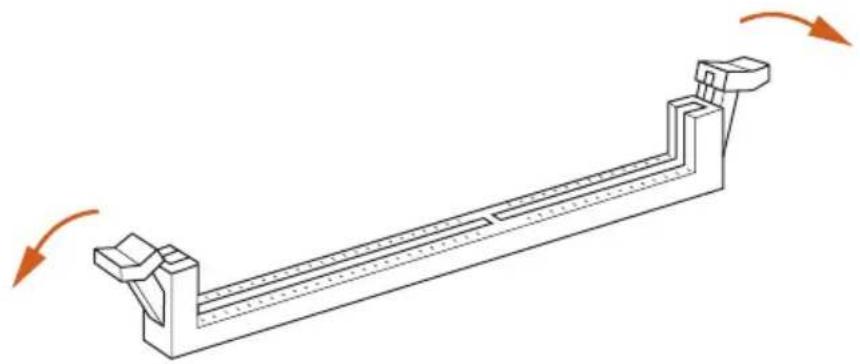
2.1 Installing Memory Modules (DIMM)
This motherboard provides two 240-pin DDR3 (Double Data Rate 3) DIMM slots.

It is not allowed to install a DDR or DDR2 memory module into a DDR3 slot; otherwise, this motherboard and DIMM may be damaged.

The DIMM only fits in one correct orientation. It will cause permanent damage to the motherboard and the DIMM if you force the DIMM into the slot at incorrect orientation.
1
natural_image
Technical line drawing of a mechanical support structure with rotational arrows indicating motion (no text or symbols)2
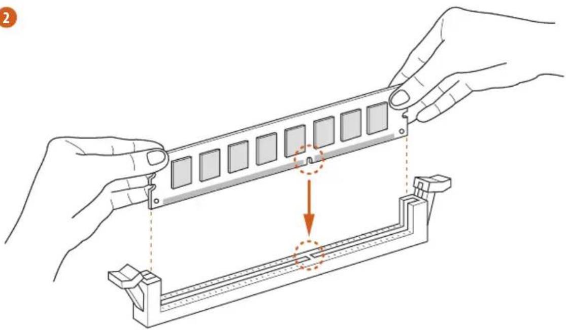
natural_image
Illustration of hands assembling a mechanical component with a highlighted section (no text or symbols)3
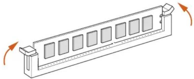
natural_image
Isometric line drawing of a rectangular structure with multiple square panels and directional arrows indicating rotation (no text or symbols)2.2 Expansion Slots (PCI Express Slots)
There are 2 PCI Express slots on the motherboard.

Before installing an expansion card, please make sure that the power supply is switched off or the power cord is unplugged. Please read the documentation of the expansion card and make necessary hardware settings for the card before you start the installation.
PCIe slots:
PCIE1 (PCIe 2.0 x16 slot) is used for PCI Express x4 lane width graphics cards. MPCIE1 (mini-PCIe slot) is used for WiFi module.
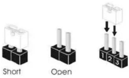
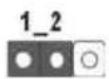
2.3 Jumpers Setup
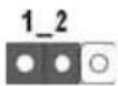
The illustration shows how jumpers are setup. When the jumper cap is placed on the pins, the jumper is "Short". If no jumper cap is placed on the pins, the jumper is "Open". The illustration shows a 3-pin jumper whose pin1 and pin2 are "Short" when a jumper cap is placed on these 2 pins.
Clear CMOS Jumper (CLRCMOS1)
(see p.1, No. 3)
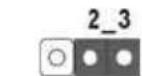
Clear CMOSDefault
CLRCMOS1 allows you to clear the data in CMOS. To clear and reset the system parameters to default setup, please turn off the computer and unplug the power cord from the power supply. After waiting for 15 seconds, use a jumper cap to short pin2 and pin3 on CLRCMOS1 for 5 seconds. However, please do not clear the CMOS right after you update the BIOS. If you need to clear the CMOS when you just finish updating the BIOS, you must boot up the system first, and then shut it down before you do the clear-CMOS action. Please be noted that the password, date, time, and user default profile will be cleared only if the CMOS battery is removed.
2.4 Onboard Headers and Connectors

Onboard headers and connectors are NOT jumpers. Do NOT place jumper caps over these headers and connectors. Placing jumper caps over the headers and connectors will cause permanent damage to the motherboard.
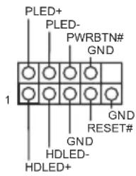
System Panel Header (9-pin PANEL1) (see p.1, No. 7)
text_image
PLED+ PLED- PWRBTN# GND 1 GND RESET# GND HDLED- HDLED+Connect the power switch, reset switch and system status indicator on the chassis to this header according to the pin assignments below. Note the positive and negative pins before connecting the cables.

PWRBTN (Power Switch):
Connect to the power switch on the chassis front panel. You may configure the way to turn off your system using the power switch.
RESET (Reset Switch):
Connect to the reset switch on the chassis front panel. Press the reset switch to restart the computer if the computer freezes and fails to perform a normal restart.
PLED (System Power LED):
Connect to the power status indicator on the chassis front panel. The LED is on when the system is operating. The LED keeps blinking when the system is in S3 sleep state. The LED is off when the system is in S4 sleep state or powered off (S5).
HDLED (Hard Drive Activity LED):
Connect to the hard drive activity LED on the chassis front panel. The LED is on when the hard drive is reading or writing data.
The front panel design may differ by chassis. A front panel module mainly consists of power switch, reset switch, power LED, hard drive activity LED, speaker and etc. When connecting your chassis front panel module to this header, make sure the wire assignments and the pin assignments are matched correctly.
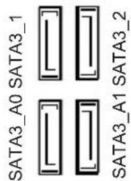
Serial ATA3 Connectors
(SATA3_1:
see p.1, No. 8)
(SATA3_2:
see p.1, No. 9)
(SATA3_A0:
see p.1, No. 11)
(SATA3_A1:
see p.1, No. 10)
text_image
SATA3_A0 SATA3_1 SATA3_A1 SATA3_2These four SATA3
connectors support SATA data cables for internal storage devices with up to
6.0 Gb/s data transfer rate.
USB 2.0 Headers
(9-pin USB2_3)
(see p.1, No. 16)
(9-pin USB4_5)
(see p.1, No. 15)
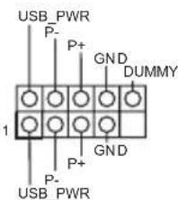
text_image
USB_PWR P- P+ GND DUMMY 1 P- P+ GND USB_PWRBesides two USB 2.0 ports on the I/O panel, there are two headers on this motherboard. Each USB
2.0 header can support two ports.
USB 3.0 Header
(19-pin USB3_2_3)
(see p.1, No. 1)
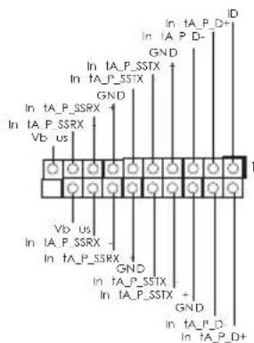
text_image
In tA_P_D+ In tA_P_D- GND In tA_P_SSTX GND In tA_P_SSTX GND In tA_P_SSRX GND In tA_P_SSTX GND In tA_P_SSTX GND In tA_P_SSTX GND In tA_P_D- GND In tA_P_D+Besides four USB 3.0 ports on the I/O panel, there is one header on this motherboard. This USB 3.0 header can support two ports.
Front Panel Audio Header
(9-pin HD_AUDIO1)
(see p.1, No. 18)
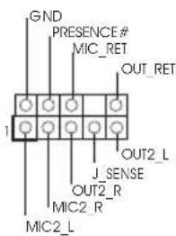
text_image
GND PRESENCE# MIC_RET OUT_RET 1 J_SENSE OUT2_R MIC2_R MIC2_LThis header is for connecting audio devices to the front audio panel.

- High Definition Audio supports Jack Sensing, but the panel wire on the chassis must support HDA to function correctly. Please follow the instructions in our manual and chassis manual to install your system.
- If you use an AC'97 audio panel, please install it to the front panel audio header by the steps below:
A. Connect Mic_IN (MIC) to MIC2_L.
B. Connect Audio_R (RIN) to OUT2_R and Audio_L (LIN) to OUT2_L.
C. Connect Ground (GND) to Ground (GND).
D. MIC_RET and OUT_RET are for the HD audio panel only. You don't need to connect them for the AC'97 audio panel.
E. To activate the front mic, go to the "FrontMic" Tab in the Realtek Control panel and adjust "Recording Volume".
Chassis Speaker Header
(4-pin SPEAKER1)
(see p.1, No. 12)
DUMMY SPEAKER
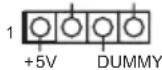
Please connect the chassis
speaker to this header.
Chassis Fan Connectors
(4-pin CHA_FAN1)
(see p.1, No. 4)
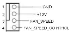
Please connect fan cables to the fan connectors and match the black wire to the ground pin.
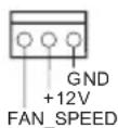
(3-pin CHA_FAN2)
(see p.1, No. 6)
CPU Fan Connector
(3-pin CPU_FAN1)
(see p.1, No. 13)
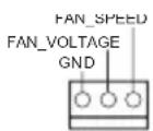
Please connect fan cables to the fan connectors and match the black wire to the ground pin.
ATX Power Connector
(24-pin ATXPWR1)
(see p.1, No. 5)
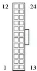
This motherboard provides a 24-pin ATX power connector. To use a 20-pin ATX power supply, please plug it along Pin 1 and Pin 13.
Serial Port Header
(9-pin COM1)
(see p.1, No. 14)
RRXD1
TR#1
DDSR#1
CCTS#1
1
BRI#1
RRTS#1
GND
TTXD1
DDCD#1
This COM1 header supports a serial port module.
TPM Header
(17-pin TPMS1)
(see p.1, No. 17)
| PCICLK | GND |
| FRAME | SMB_CLK_MAIN |
| PCIRST# | SMB_DATA_MAIN |
| LAD3 | LAD2 |
| +3V | LAD1 |
| LAD0 | GND |
| S_PWRDOWN# | |
| +3VSB | SERIRQ# |
| GND | GND |
This connector supports Trusted Platform Module (TPM) system, which can securely store keys, digital certificates, passwords, and data. A TPM system also helps enhance network security, protects digital identities, and ensures platform integrity.
1 Einleitung
text_image
Short OpenSerial-ATA-III-Anschlüsse
(SATA3_1:
siehe S. 1, Nr. 8)
(SATA3_2:
siehe S. 1, Nr. 9)
(SATA3_A0:
siehe S. 1, Nr. 11)
(SATA3_A1:
siehe S. 1, Nr. 10)

text_image
SATA3_A0 SATA3_1 SATA3_A1 SATA3_2text_image
USB_PWR P- P+ GND DUMMY 1 GND P+ P- USB_PWR P-(Trusted Platform Module
text_image
Short Opentext_image
Short Openbit / 7 32-bit / 7 64-bit / XP 32-bit / XP 64-bit
text_image
Short Open清除 CMOS 跳线 (CLRCMOS1)
(见第 1 页,第 3 个)
2_3 清除 CMOS默认
If you need to contact ASRock or want to know more about ASRock, you're welcome to visit ASRock's website at http://www.asrock.com; or you may contact your dealer for further information. For technical questions, please submit a support request form at http://www.asrock.com/support/tsd.asp
ASRock Incorporation
2F., No.37, Sec. 2, Jhongyang S. Rd., Beitou District,
Taipei City 112, Taiwan (R.O.C.)
ASRock EUROPE B.V.
Bijsterhuizen 3151
6604 LV Wijchen
The Netherlands
Phone: +31-24-345-44-33
Fax: +31-24-345-44-38
ASRock America, Inc.
13848 Magnolia Ave, Chino, CA91710
U.S.A.
Phone: +1-909-590-8308
Fax: +1-909-590-1026