
J3455-ITX - Motherboard ASROCK - Free user manual and instructions
Find the device manual for free J3455-ITX ASROCK in PDF.

| Product Type | Motherboard |
| Brand | ASRock |
| Model | J3455-ITX |
| Form Factor | Mini-ITX (17 x 17 cm) |
| Integrated CPU | Intel Quad-Core J3455 (up to 2.3 GHz) |
| Chipset | Integrated Intel SoC |
| Memory | 2 x DDR3L DIMM, up to 16 GB, 1600 MHz (max 750 MHz per manual) |
| Storage | 4 x SATA3 (6 Gb/s) |
| USB Ports | 2 x USB 3.0 (rear), 2 x USB 2.0 (rear), 2 x USB 3.0 via header, 2 x USB 2.0 via header |
| Video Outputs | 1 x HDMI, 1 x DVI-D |
| Audio | Realtek ALC887, 7.1 HD channels |
| Networking | Gigabit LAN (Realtek RTL8111H) |
| Internal Connectors | 1 x USB 3.0 header, 2 x USB 2.0 headers, 1 x HD audio header, 1 x COM, 1 x TPM, 1 x CPU fan connector, 1 x chassis fan connector |
| Rear Panel | 1 x HDMI, 1 x DVI-D, 2 x USB 3.0, 2 x USB 2.0, 1 x RJ45, 3 x audio jacks (line in, front out, mic) |
| Power Supply | ATX 24-pin |
| BIOS | AMI UEFI with GUI |
| Operating System | Windows 10 compatible (drivers available) |
| Operating Temperature | 0 °C to 40 °C (estimated) |
Frequently Asked Questions - J3455-ITX ASROCK
User questions about J3455-ITX ASROCK
0 question about this device. Answer the ones you know or ask your own.
Ask a new question about this device
Download the instructions for your Motherboard in PDF format for free! Find your manual J3455-ITX - ASROCK and take your electronic device back in hand. On this page are published all the documents necessary for the use of your device. J3455-ITX by ASROCK.
USER MANUAL J3455-ITX ASROCK
Published August 2016
Copyright©2016 ASRock INC. All rights reserved.
Copyright Notice:
No part of this documentation may be reproduced, transcribed, transmitted, or translated in any language, in any form or by any means, except duplication of documentation by the purchaser for backup purpose, without written consent of ASRock Inc.
Products and corporate names appearing in this documentation may or may not be registered trademarks or copyrights of their respective companies, and are used only for identification or explanation and to the owners' benefit, without intent to infringe.
Disclaimer:
Specifications and information contained in this documentation are furnished for informational use only and subject to change without notice, and should not be constructed as a commitment by ASRock. ASRock assumes no responsibility for any errors or omissions that may appear in this documentation.
With respect to the contents of this documentation, ASRock does not provide warranty of any kind, either expressed or implied, including but not limited to the implied warranties or conditions of merchantability or fitness for a particular purpose.
In no event shall ASRock, its directors, officers, employees, or agents be liable for any indirect, special, incidental, or consequential damages (including damages for loss of profits, loss of business, loss of data, interruption of business and the like), even if ASRock has been advised of the possibility of such damages arising from any defect or error in the documentation or product.

This device complies with Part 15 of the FCC Rules. Operation is subject to the following two conditions:
(1) this device may not cause harmful interference, and
(2) this device must accept any interference received, including interference that may cause undesired operation.
CALIFORNIA, USA ONLY
The Lithium battery adopted on this motherboard contains Perchlorate, a toxic substance controlled in Perchlorate Best Management Practices (BMP) regulations passed by the California Legislature. When you discard the Lithium battery in California, USA, please follow the related regulations in advance.
"Perchlorate Material-special handling may apply, see www.dtsc.ca.gov/hazardouswaste/perchlorate"
ASRock Website: http://www.asrock.com
AUSTRALIA ONLY
Our goods come with guarantees that cannot be excluded under the Australian Consumer Law. You are entitled to a replacement or refund for a major failure and compensation for any other reasonably foreseeable loss or damage caused by our goods. You are also entitled to have the goods repaired or replaced if the goods fail to be of acceptable quality and the failure does not amount to a major failure. If you require assistance please call ASRock Tel: +886-2-28965588 ext.123 (Standard International call charges apply)
The terms HDMI ^™ and HDMI High-Definition Multimedia Interface, and the HDMI logo are trademarks or registered trademarks of HDMI Licensing LLC in the United States and other countries.

HIGH-DEFINITION MULTIMEDIA INTERFACE
Motherboard Layout
text_image
ASRock PS2 Mouse Keydo and VGA1 DV11 HDMI1 USB 3.0 T: USB2 B: USB3 USB 2.0 T: USB4 B: USB5 DJ-45 LAN LAN DDR3_A1 Front USB 3.0 CDI_B1 PCIE1 HD_AUDIO1 SATA3_A1 SATA3_1 SATA3_A2 SATA3_2 CPU_FAN1 CLRMOS1 RoHS CMOS Battery TPMS1 ATXPWR1 COM1 USB3_0_1 CHA_FAN1 SPK_CII LCD_PWRD9 RHOLED盘片 PANEL1 151617 14 13 12 11 10 9 1 2 3 4 5 6 7 8No. Description
1 CPU Fan Connector (CPU_FAN1)
2 Clear CMOS Jumper (CLRMOS1)
3 TPM Header (TPMS1)
4 ATX Power Connector (ATXPWR1)
5 2 x 204-pin DDR3 SO-DIMM Slots (DDR3_A1, DDR3_B1)
6 COM Port Header (COM1)
7 System Panel Header (PANEL1)
8 Chassis Intrusion and Speaker Header (SPK_CI1)
9 USB 2.0 Header (USB_0_1)
10 Chassis Fan Connector (CHA_FAN1)
11 USB 3.0 Header (USB3_0_1)
12 USB 2.0 Header (USB6)
13 SATA3 Connector (SATA3_1)
14 SATA3 Connector (SATA3_2)
15 SATA3 Connector (SATA3_A2)
16 SATA3 Connector (SATA3_A1)
17 Front Panel Audio Header (HD_AUDIO1)
I/O Panel

text_image
Diagram showing labeled electronic device ports and connectors, including VGA, Ethernet, and USB interface modules with numbered labels.No. Description No. Description
1 PS/2 Mouse Port 8 Microphone (Pink)
2 D-Sub Port 9 Optical SPDIF Out Port
3 LAN RJ-45 Port* 10 USB 2.0 Ports (USB45)
4 Central / Bass (Orange) 11 USB 3.0 Ports (USB3_23)
5 Rear Speaker (Black) 12 HDMI Port
6 Line In (Light Blue) 13 DVI-D Port
7 Front Speaker (Lime) ^** 14 PS/2 Keyboard Port
* There are two LEDs on each LAN port. Please refer to the table below for the LAN port LED indications.

| Activity / Link LED Speed LED | |||
| Status Description Status Description | |||
| Off No Link Off | 10Mbps connection | ||
| Blinking | Data Activity | Orange | 100Mbps connection |
| On Link Green | Gbps connection | ||
** If you use a 2-channel speaker, please connect the speaker's plug into "Front Speaker Jack". See the table below for connection details in accordance with the type of speaker you use.
| Audio Output Channels | Front Speaker (No. 7) | Rear Speaker (No. 5) | Central / Bass (No. 4) | Line In (No. 6) |
| 2 V -- -- -- | ||||
| 4 V V -- -- | ||||
| 6 V V V -- | ||||
| 8 V V V V |

To enable Multi-Streaming, you need to connect a front panel audio cable to the front panel audio header. After restarting your computer, you will find the "Mixer" tool on your system. Please select "Mixer ToolBox", click "Enable playback multi-streaming", and click "ok". Choose "2CH", "4CH", "6CH", or "8CH" and then you are allowed to select "Realtek HDA Primary output" to use the Rear Speaker, Central/Bass, and Front Speaker, or select "Realtek HDA Audio 2nd output" to use the front panel audio.
Chapter 1 Introduction
Thank you for purchasing ASRock J4205-ITX/J3455-ITX motherboard, a reliable motherboard produced under ASRock's consistently stringent quality control. It delivers excellent performance with robust design conforming to ASRock's commitment to quality and endurance.

Because the motherboard specifications and the BIOS software might be updated, the content of this documentation will be subject to change without notice. In case any modifications of this documentation occur, the updated version will be available on ASRock's website without further notice. If you require technical support related to this motherboard, please visit our website for specific information about the model you are using. You may find the latest VGA cards and CPU support list on ASRock's website as well. ASRock website http://www.asrock.com.
1.1 Package Contents
ASRock J4205-ITX/J3455-ITX Motherboard (Mini-ITX Form Factor)
ASRock J4205-ITX/J3455-ITX Quick Installation Guide
ASRock J4205-ITX/J3455-ITX Support CD
2 x Serial ATA (SATA) Data Cables (Optional)
1 x I/O Panel Shield
1 x WiFi Module Screw (Optional)
1.2 Specifications
| Platform | Mini-ITX Form FactorSolid Capacitor design |
| CPU | Intel® Quad-Core Pentium® Processor J4205 (up to 2.6 GHz)(for J4205-ITX)Intel® Quad-Core Processor J3455 (up to 2.3 GHz)(for J3455-ITX) |
| Memory | Dual Channel DDR3/DDR3L Memory Technology2 x DDR3/DDR3L SO-DIMM Slots* 2GB DRAM is not supported.Supports DDR3/DDR3L 1866/1600/1333 non-ECC, un-buffered memoryMax. capacity of system memory: 16GB |
| Expansion Slot | 1 x PCI Express 2.0 x1 Slot1 x M.2 Socket (Key E), supports type 2230 WiFi/BT module |
| Graphics | 800MHz) (for J4205-ITX)750MHz) (for J3455-ITX)(4096x2160) @ 60Hz60Hz60HzAudio) with HDMI Port (Compliant HDMI monitor is required)HEVC (H.265) 10b @ MP level 5.1 (GPU accelerated), JPEG, VP8, VP9and HDMI Ports |
| Audio | 7.1 CH HD Audio with Content Protection (Realtek ALC892 Audio Codec)* To configure 7.1 CH HD Audio, it is required to use an HD front panel audio module and enable the multi-channel audio feature through the audio driver.Premium Blu-ray Audio supportSupports Surge Protection (ASRock Full Spike Protection)ELNA Audio Caps |
| LAN | PCIE x1 Gigabit LAN 10/100/1000 Mb/sRealtek RTL8111GRSupports Wake-On-WANSupports Lightning/ESD Protection (ASRock Full Spike Protection)Supports LAN Cable DetectionSupports Energy Efficient Ethernet 802.3azSupports PXE |
| Rear Panel I/O | 1 x PS/2 Mouse Port1 x PS/2 Keyboard Port1 x D-Sub Port1 x DVI-D Port1 x HDMI Port1 x Optical SPDIF Out Port2 x USB 2.0 Ports (Supports ESD Protection (ASRock Full Spike Protection))2 x USB 3.0 Ports (Supports ESD Protection (ASRock Full Spike Protection))1 x RJ-45 LAN Port with LED (ACT/LINK LED and SPEED LED)HD Audio Jacks: Side Speaker / Rear Speaker / Central / Bass / Line in / Front Speaker / Microphone |
| Storage | 2 x SATA3 6.0 Gb/s Connectors, support NCQ, AHCI and Hot Plug2 x SATA3 6.0 Gb/s Connectors by ASMedia ASM1061, support NCQ, AHCI and Hot Plug |
Connector
1 x COM Port Header 1 x TPM Header 1 x Chassis Intrusion and Speaker Header 1 x CPU Fan Connector (3-pin) 1 x Chassis Fan Connector (3-pin) 1 x 24 pin ATX Power Connector 1 x Front Panel Audio Connector 2 x USB 2.0 Headers (Support 3 USB 2.0 ports) (Supports ESD Protection (ASRock Full Spike Protection)) 1 x USB 3.0 Header (Supports 2 USB 3.0 ports) (Supports ESD Protection (ASRock Full Spike Protection)) * USB3_0_1 is shared with USB_0_1.
BIOS
AMI UEFI Legal BIOS with GUI support
Feature
Supports Plug and Play
ACPI 5.0 compliant wake up events
Supports jumperfree
SMBIOS 2.7 support
Hardware
CPU/Chassis temperature sensing
Monitor
CPU/Chassis Fan Tachometer
CPU/Chassis Quiet Fan (Auto adjust chassis fan speed by
CPU temperature)
CPU/Chassis Fan multi-speed control
Voltage monitoring: +12V, +5V, +3.3V, CPU Vcore
OS
Microsoft® Windows® 10 64-bit
* For the updated Windows* 10 driver, please visit ASRock's
website for details: http://www.asrock.com
Linux: Ubuntu 16.10 / Fedora 25
Certifica-
FCC, CE, WHQL
tions
ErP/EuP ready (ErP/EuP ready power supply is required)
Chapter 2 Installation
This is a Mini-ITX form factor motherboard. Before you install the motherboard, study the configuration of your chassis to ensure that the motherboard fits into it.
Pre-installation Precautions
Take note of the following precautions before you install motherboard components or change any motherboard settings.
Make sure to unplug the power cord before installing or removing the motherboard.
Failure to do so may cause physical injuries to you and damages to motherboard components.
In order to avoid damage from static electricity to the motherboard's components,
NEVER place your motherboard directly on a carpet. Also remember to use a grounded wrist strap or touch a safety grounded object before you handle the components.
Hold components by the edges and do not touch the ICs.
Whenever you uninstall any components, place them on a grounded anti-static pad or in the bag that comes with the components.
When placing screws to secure the motherboard to the chassis, please do not over-tighten the screws! Doing so may damage the motherboard.
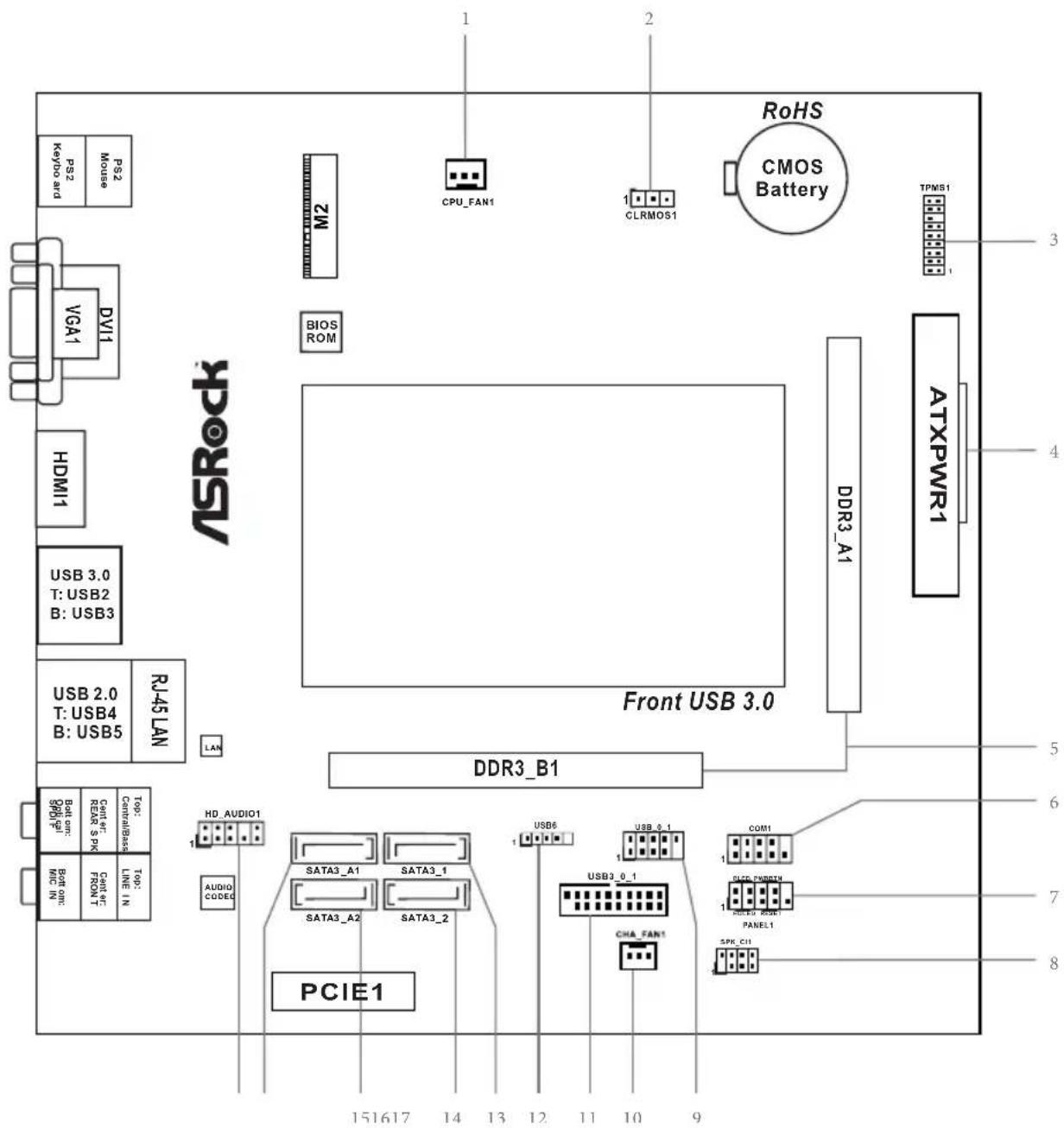
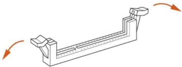
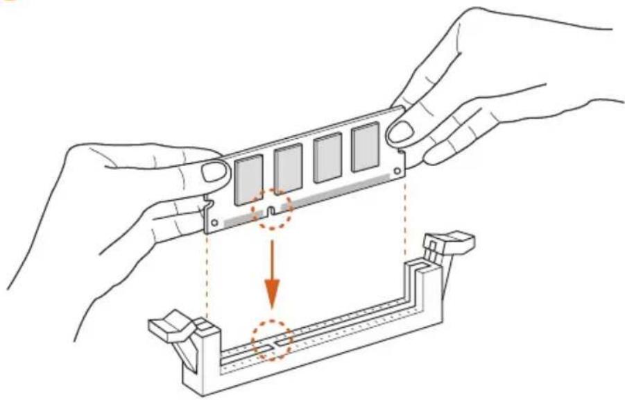
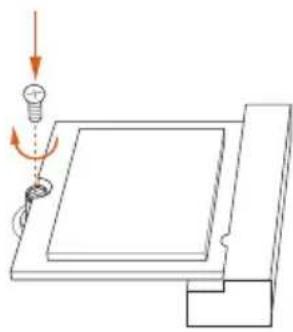
2.1 Installing Memory Modules (SO-DIMM)
☐is motherboard provides two 204-pin DDR3/DDR3L (Double Data Rate 3) SO-DIMM slots.

It is not allowed to install a DDR or DDR2 memory module into a DDR3/DDR3L slot; otherwise, this motherboard and SO-DIMM may be damaged.

The SO-DIMM only fits in one correct orientation. It will cause permanent damage to the motherboard and the SO-DIMM if you force the SO-DIMM into the slot at incorrect orientation.
1
natural_image
Isometric line drawing of a mechanical component with arrows indicating motion direction (no text or symbols)2
natural_image
Illustration of hands assembling a mechanical component with an arrow indicating motion (no text or symbols present)3
natural_image
Technical line drawing of a mechanical component with five rectangular slots and directional arrows indicating rotation (no text or symbols)2.2 Expansion Slot (PCI Express Slot)
There is 1 PCI Express slot on the motherboard.

Before installing an expansion card, please make sure that the power supply is switched off or the power cord is unplugged. Please read the documentation of the expansion card and make necessary hardware settings for the card before you start the installation.
PCIe slot:
PCIE1 (PCIe 2.0 x1 slot) is used for PCI Express cards with x1 lane width cards.
Warning:
To ensure better graphics compatibility, the BIOS is set to "boot from Onboard VGA" as default even the user install a VGA card on PCIe slot.
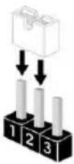
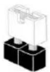
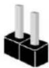
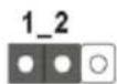
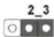
2.3 Jumpers Setup
The illustration shows how jumpers are setup. When the jumper cap is placed on the pins, the jumper is "Short". If no jumper cap is placed on the pins, the jumper is "Open". The illustration shows a 3-pin jumper whose pin1 and pin2 are "Short" when a jumper cap is placed on these 2 pins.

Short

Open
Clear CMOS Jumper (CLRMOS1)
(see p.1, No. 2)

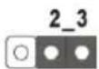
Clear CMOSDefault
CLRMOS1 allows you to clear the data in CMOS. To clear and reset the system parameters to default setup, please turn off the computer and unplug the power cord from the power supply. After waiting for 15 seconds, use a jumper cap to short pin2 and pin3 on CLRMOS1 for 5 seconds. However, please do not clear the CMOS right after you update the BIOS. If you need to clear the CMOS when you just finish updating the BIOS, you must boot up the system first, and then shut it down before you do the clear-CMOS action. Please be noted that the password, date, time, and user default profile will be cleared only if the CMOS battery is removed.

If you clear the CMOS, the case open may be detected. Please adjust the BIOS option "Clear Status" to clear the record of previous chassis intrusion status.
2.4 Onboard Headers and Connectors

Onboard headers and connectors are NOT jumpers. Do NOT place jumper caps over these headers and connectors. Placing jumper caps over the headers and connectors will cause permanent damage to the motherboard.
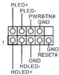
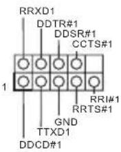
System Panel Header (9-pin PANEL1) (see p.1, No. 7)
text_image
PLED+ PLED- PWRBTN# GND 1 GND RESET# GND HDLED- HDLED+Connect the power switch, reset switch and system status indicator on the chassis to this header according to the pin assignments below. Note the positive and negative pins before connecting the cables.

PWRBTN (Power Switch):
Connect to the power switch on the chassis front panel. You may configure the way to turn off your system using the power switch.
RESET (Reset Switch):
Connect to the reset switch on the chassis front panel. Press the reset switch to restart the computer if the computer freezes and fails to perform a normal restart.
PLED (System Power LED):
Connect to the power status indicator on the chassis front panel. The LED is on when the system is operating. The LED keeps blinking when the system is in S1/S3 sleep state. The LED is off when the system is in S4 sleep state or powered off (S5).
HDLED (Hard Drive Activity LED):
Connect to the hard drive activity LED on the chassis front panel. The LED is on when the hard drive is reading or writing data.
The front panel design may differ by chassis. A front panel module mainly consists of power switch, reset switch, power LED, hard drive activity LED, speaker and etc. When connecting your chassis front panel module to this header, make sure the wire assignments and the pin assignments are matched correctly.
Chassis Intrusion and Speaker Header (7-pin SPK_CI1) (see p.1, No. 8)
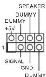
Please connect the chassis intrusion and the chassis speaker to this header.
Serial ATA3 Connectors
(SATA3_1:
see p.1, No. 13)
(SATA3_2:
see p.1, No. 14)
(SATA3_A1:
see p.1, No. 16)
(SATA3_A2:
see p.1, No. 15)
SATA3_A1 SATA3_1
SATA3_A2 SATA3_2
These four SATA3
connectors support SATA data cables for internal storage devices with up to 6.0 Gb/s data transfer rate.
USB 2.0 Headers
(4-pin USB6)
(see p.1, No. 12)
(9-pin USB_0_1)
(see p.1, No. 9)

Besides two USB 2.0 ports on the I/O panel, there are two headers on this motherboard.
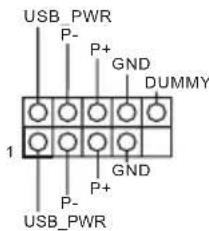
text_image
USB_PWR P- P+ GND DUMMY 1 P- GND P+ USB_PWRUSB 3.0 Header
(19-pin USB3_0_1)
(see p.1, No. 11)

text_image
IntA_P_D + IntA_P_D - GN_D IntA_P_SSTX+ GN_D IntA_P_SSRX + Vbu_s Vbu_s IntA_P_SSRX - IntA_P_SSRX + GN_D IntA_P_SSTX- IntA_P_SSTX+ GN_D IntA_P_D - IntA_P_D + ID 1Besides two USB 3.0 ports on the I/O panel, there is one header on this motherboard. This USB 3.0 header can support two ports.
Front Panel Audio Header
(9-pin HD_AUDIO1)
(see p.1, No. 17)

text_image
GND PRESENCE# MIC_RET OUT_RET 1 J_SENSE OUT2_R MIC2_R MIC2_LThis header is for
connecting audio devices to the front audio panel.

- High Definition Audio supports Jack Sensing, but the panel wire on the chassis must support HDA to function correctly. Please follow the instructions in our manual and chassis manual to install your system.
- If you use an AC'97 audio panel, please install it to the front panel audio header by the steps below:
A. Connect Mic_IN (MIC) to MIC2_L.
B. Connect Audio_R (RIN) to OUT2_R and Audio_L (LIN) to OUT2_L.
C. Connect Ground (GND) to Ground (GND).
D. MIC_RET and OUT_RET are for the HD audio panel only. You don't need to connect them for the AC'97 audio panel.
E. To activate the front mic, go to the "FrontMic" Tab in the Realtek Control panel and adjust "Recording Volume".
Chassis Fan Connector (3-pin CHA_FAN1) (see p.1, No. 10)
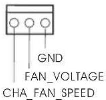
text_image
GND FAN_VOLTAGE CHA_FAN_SPEEDPlease connect fan cable to the fan connector and match the black wire to the ground pin.
CPU Fan Connector (3-pin CPU_FAN1) (see p.1, No. 1)

text_image
GND FAN_VOLTAGE CPU_FAN_SPEEDPlease connect the CPU fan cable to the connector and match the black wire to the ground pin.
ATX Power Connector (24-pin ATXPWR1) (see p.1, No. 4)

This motherboard provides a 24-pin ATX power connector. To use a 20-pin ATX power supply, please plug it along Pin 1 and Pin 13.
TPM Header (17-pin TPMS1) (see p.1, No. 3)
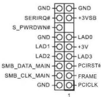
text_image
GND SERIRQ# S_PWRDWN# GND LAD0 LAD1 +3V LAD2 LAD3 SMB_DATA_MAIN PCIRST# SMB_CLK_MAIN FRAME GND PCICLK 1This connector supports Trusted Platform Module (TPM) system, which can securely store keys, digital certificates, passwords, and data. A TPM system also helps enhance network security, protects digital identities, and ensures platform integrity.
Serial Port Header
(9-pin COM1)
(see p.1, No. 6)
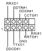
This COM1 header supports a serial port module.
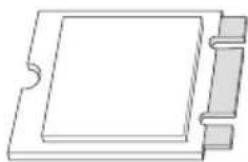
2.5 M.2 WiFi/BT Module Installation Guide
The M.2, also known as the Next Generation Form Factor (NGFF), is a small size and versatile card edge connector that aims to replace mPCIe and mSATA. The M.2 Socket (Key E) supports type 2230 WiFi/BT module.
* The M.2 socket does not support SATA M.2 SSDs.
Installing the WiFi/BT module

natural_image
Pure technical line drawing of a mechanical component with no text or symbolsStep 1
Prepare a type 2230 WiFi/BT module and the screw.
natural_image
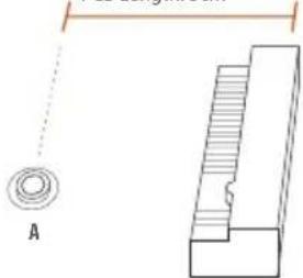
Pure electrical circuit lines without any symbolsModule Type: Type2230
PCB Length: 3cm
natural_image
Technical diagram showing a circular component labeled 'A' and a stepped mechanical part with hatching (no text or symbols present)Step 2
Find the nut location to be used.

natural_image
Diagram of a mechanical or electronic component with labeled section A and crosshair symbol (no readable text or symbols)
natural_image
Pure mechanical assembly diagram showing a shaft and housing with no text or symbolsStep 3
Align and gently insert the WiFi/BT module into the M.2 slot. Please be aware that the module only fits in one orientation.
natural_image
Diagram showing a light bulb interacting with a rectangular panel, with an arrow indicating rotation (no text or symbols present)Step 4
Tighten the screw with a screwdriver to secure the module into place. Please do not overtighten the screw as this might damage the module.
1 Einleitung
DDR3L 1866/1600/1333
Fente
d'expansion
BT type 2230
Graphiques
Auto Lip Sync, xvYCC 및 HBR (High Bit Rate Audio)(HDMI
TPM(Trusted Platform
Module)시스템을 지원합니다
다.TPM 시스템은 네트워크
보안을 강화하고,디지털 신
원을 보호하며 플랫폼 무결
성을 유지합니다.
시리얼 포트 헤더
(9 핀 COM1)
(1페이지,6번 항목 참조)
이 COM1 헤더는 시리얼
포트 모듈을 지원합니다.

natural_image
Simple graphic with a magnifying glass icon and a horizontal line, no text or symbols present.1.1 パッケージの内容
1.2 仕様
CPU
GHz) (J4205-ITX)
(J3455-ITX)
(J4205-ITX)
HDMI
LAN

natural_image
Blank white image with no visible content, text, or symbolsos
1.3 ジャンパー設定
Short
Open

(CLRCMOS1)

1.
2.
Enabling USB Ports for Windows® 7 Installation
Intel® Braswell and Skylake has removed their support for the Enhanced Host Controller Interface (EHCI – USB2.0) and only kept the eXtensible Host Controller Interface (XHCI – USB3.0). Due to that fact that XHCI is not included in the Windows 7 inbox drivers, users may find it difficult to install Windows 7 operating system because the USB ports on their motherboard won’t work. In order for the USB ports to function properly, please create a Windows® 7 installation disk with the Intel® USB 3.0 eXtensible Host Controller (xHCI) drivers packed into the ISO file.
Requirements
A Windows ^® 7 installation disk or USB drive
A Windows ^® PC
Win7 USB Patcher (included in the ASRock Support CD or downloaded from website)
Scenarios
You have an ODD and PS/2 ports:
If there is an optical disc drive, PS/2 ports and PS/2 Keyboard or mouse on your computer, you can skip the instructions below and go ahead to install Windows ^® 7 OS.
You only have an ODD (For Intel Skylake platforms only):
If there is an optical disc drive but no PS/2 ports on your computer, please enable the "PS/2 Simulator" option in UEFI SETUP UTILITY > Advanced > USB Configuration, which allows the USB port to function as a PS/2 port, and then you can install the Windows ^® 7 OS. Please set PS/S Simulator back to disabled after the installation.
You've got nothing:
If you do not have an optical disc drive, please find another computer and follow the instructions below to create a new ISO file with the "Win7 USB Patcher". Then use the new patched Windows ^® 7 installation USB drive to install Windows ^® 7 OS.
Instructions
Step 1
Insert the Windows* 7 installation disk or USB drive to your system.
Step 2
Extract the tool (Win7 USB Patcher) and launch it.
Step 3
Select how you want to install Windows 7 later.

text_image
ASRock WIN 7 USB PATCHER Step 1 of 4 This patcher helps you to create a Windows® 7 installation file with the USB driver bundled. Choose whether you want to install Windows® 7 from your USB device or optical disk drive later. Create a Windows 7 installation disk with a USB device Create a Windows 7 installation disk with a USB device Create a Windows 7 installation disk with a CD Create a Windows 7 installation ISO file for a CD Next >Step 4
Locate your Win7 source folder or your ISO file.

text_image
ASRock WIN 7 USB PATCHER Step 2 of 4 Locate your original Windows® 7 installation media. Try clicking refresh if it doesn't appear. ISO File USB or Optical disk Source Directory liah.iso ISO FileStep 5
Select the USB storage, compact disk or destination folder for the new Windows 7 installation file.
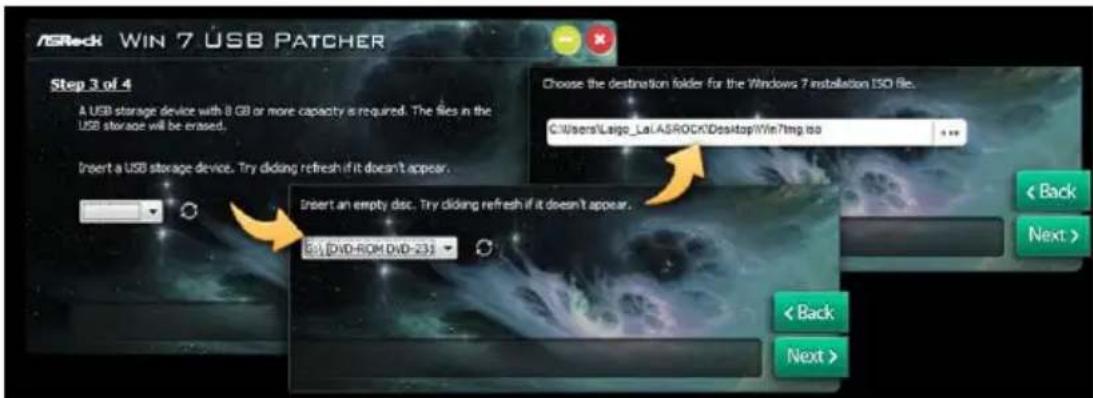
text_image
ASRock WIN 7 USB PATCHER Step 3 of 4 A USB storage device with 8 GB or more capacity is required. The files in the USB storage will be erased. Insert a USB storage device. Try clicking refresh if it doesn't appear. Choose the destination folder for the Windows 7 installation ISO Re. C:\Users\Largo_Lai.ASROCK\Desktop\Win\Temp.no Insert an empty disc. Try clicking refresh if it doesn't appear. B:\DVD-ROM DVD-23J < Back Next > < Back Next >Step 6
Click "Start" to begin.
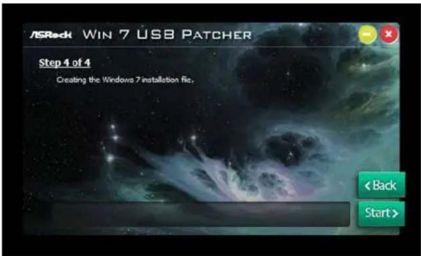
text_image
ASRock WIN 7 USB PATCHER Step 4 of 4 Creating the Windows 7 installation file. < Back Start >Step 7
Now you are able to install Windows ^® 7 on Braswell or Skylake with the new burned CD. Or please use the patched ISO image to make an OS USB drive to install the OS.
Contact Information
If you need to contact ASRock or want to know more about ASRock, you're welcome to visit ASRock's website at http://www.asrock.com; or you may contact your dealer for further information. For technical questions, please submit a support request form at http://www.asrock.com/support/tsd.asp
ASRock Incorporation
2F., No.37, Sec. 2, Jhongyang S. Rd., Beitou District,
Taipei City 112, Taiwan (R.O.C.)
ASRock EUROPE B.V.
Bijsterhuizen 11-11
6546 AR Nijmegen
The Netherlands
Phone: +31-24-345-44-33
Fax: +31-24-345-44-38
ASRock America, Inc.
13848 Magnolia Ave, Chino, CA91710
U.S.A.
Phone: +1-909-590-8308
Fax: +1-909-590-1026
For the following equipment:
Motherboard
| (Product Name) |
| J4205-ITX/J3455-ITX / ASRock |
(Model Designation / Trade Name)
| ASRock Incorporation |
| (Manufacturer Name) |
2F., No.37, Sec. 2, Jhongyang S. Rd., Beitou District, Taipei City 112, Taiwan (R.O.C.)
| (Manufacturer Address) |
| is herewith confirmed to comply with the requirements set out in the Council Directive on the Approximation of the Laws of the Member States relating to Electromagnetic Compatibility Directive (2004/108/EC) and Safety Directive (2006/95/EC), the following standards are applied: |
EN 55022: 2006+A1:2007
EN 61000-3-2: 2009
EN 61000-3-3:2008
EN 55024: 1998 + A1:2001 + A2:2003
IEC 61000-4-2: 2008;
IEC 61000-4-3: 2010; IEC 61000-4-4: 2010;
IEC 61000-4-5: 2005; IEC 61000-4-6: 2008;
IEC 61000-4-8: 2009; IEC 61000-4-11: 2004;
EN 60950-1: 2005 + A1:2009
IEC 60950-1:2006 + A11:2009 + A1:2010 + A12:2011
The following manufacturer / importer or authorized representative established within the EUT is responsible for this declaration:
ASRock EUROPE B.V.
(Company Name)
Bijsterhuizen 1111 6546 AR Nijmegen The Netherlands
(Company Address)
Person responsible for making this declaration:

(Name, Surname)
A.V.P
(Position / Title)
Sep. 30, 2016
(Date)