
YT-82380 - Milling machine Yato - Free user manual and instructions
Find the device manual for free YT-82380 Yato in PDF.

| Product Type | Router (wood milling machine) |
| Brand | Yato |
| Model | YT-82380 |
| Supply Voltage | 220-240 V ~ |
| Frequency | 50 Hz |
| Rated Power | 2100 W |
| No-load Speed | 8000 - 23500 min⁻¹ |
| Tool Holder (Collet) Size | 8 mm / 12 mm |
| Plunge Stroke | 55 mm |
| Weight | 6.6 kg |
| Electrical Protection Class | II (double insulation) |
| Protection Rating | IP20 |
| Sound Pressure Level (LpA ± KpA) | 94 ± 3 dB(A) |
| Sound Power Level (LwA ± KwA) | 105 ± 3 dB(A) |
| Vibration Level (ah ± K) | 3.41 ± 1.5 m/s² |
| Processable Materials | Wood and wood-based materials (MDF, particleboard, plywood) |
| Included Accessories | Parallel guide, circular guide, dust extraction adapter, template plate, reduction sleeve, wrench |
| Main Functions | Profiling, grooving, template copying, circular and parallel routing |
| Speed Adjustment | Continuous electronic speed control |
| Depth Adjustment | Depth gauge with micrometer, rotating stop |
| Spindle Lock | Yes, for bit change |
| Maintenance and Cleaning | Clean ventilation slots with compressed air (max 0.3 MPa) or brush; do not use chemicals |
| Warranty | Manufacturer warranty according to conditions; user disassembly voids warranty |
Frequently Asked Questions - YT-82380 Yato
User questions about YT-82380 Yato
0 question about this device. Answer the ones you know or ask your own.
Ask a new question about this device
Download the instructions for your Milling machine in PDF format for free! Find your manual YT-82380 - Yato and take your electronic device back in hand. On this page are published all the documents necessary for the use of your device. YT-82380 by Yato.
USER MANUAL YT-82380 Yato
natural_image
Black and white YATO 3 precision press machine with adjustable handle and base (no visible text or symbols)CE
PL D RUS UA LT LV CZ SK H RO E F I NL GR
natural_image
Close-up of a mechanical presser with hands operating the tool, showing a curved arrow indicating motion (no text or symbols visible)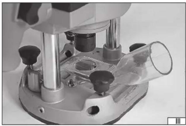
natural_image
Close-up of a laboratory microscope with transparent glass chamber and multiple test tubes (no visible text or labels)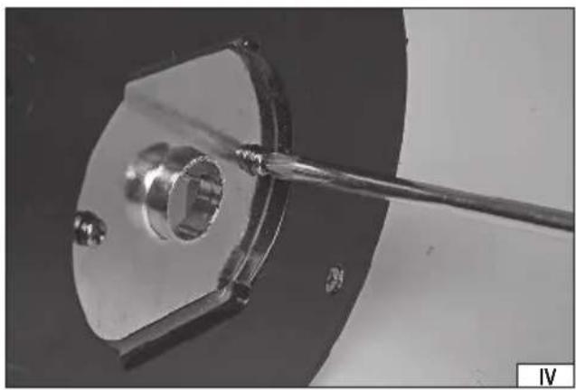
natural_image
Close-up of a mechanical component with a metal bracket and threaded rod, no visible text or symbols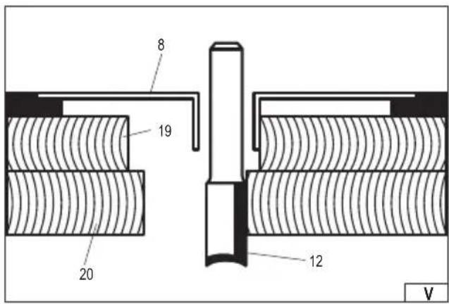

natural_image
Close-up of mechanical components with hands adjusting parts (no visible text or symbols)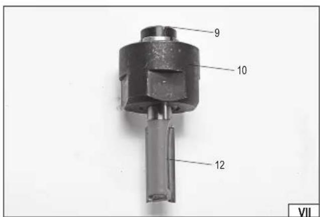
2022
natural_image
Close-up of mechanical components with bolts and springs, no visible text or symbols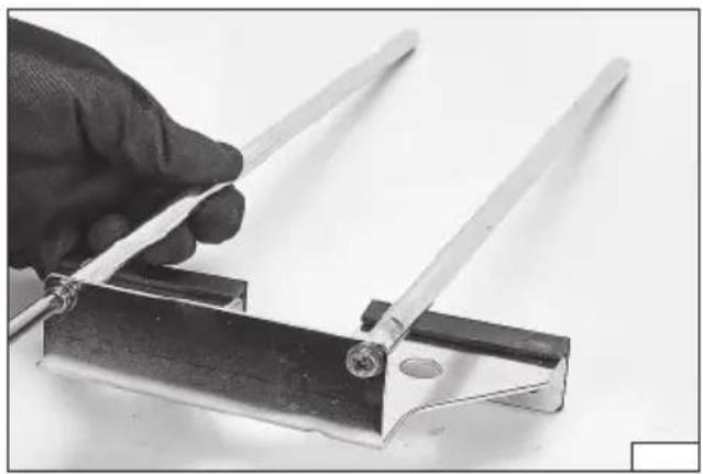
natural_image
Hand holding a metal tool with two metal rods, mounted on a metal bracket (no text or symbols visible)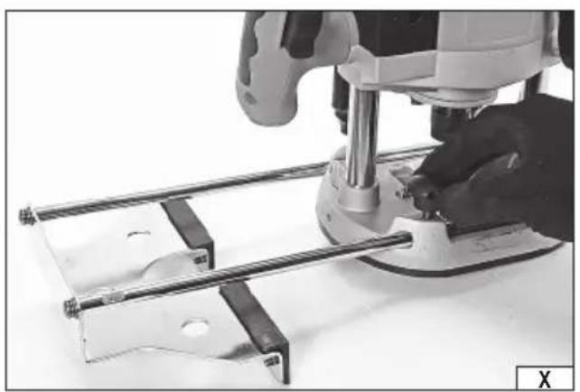
natural_image
Close-up of a hand using a tool to adjust metal components on a metal frame (no visible text or symbols)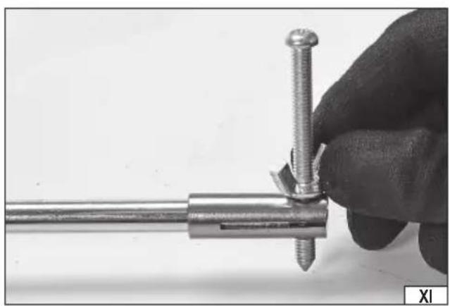
natural_image
Close-up of a hand holding a metal tool with a screw and bracket, no visible text or symbols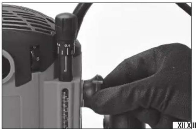
natural_image
Close-up of a hand operating a power tool with a dial indicator (no visible text or symbols)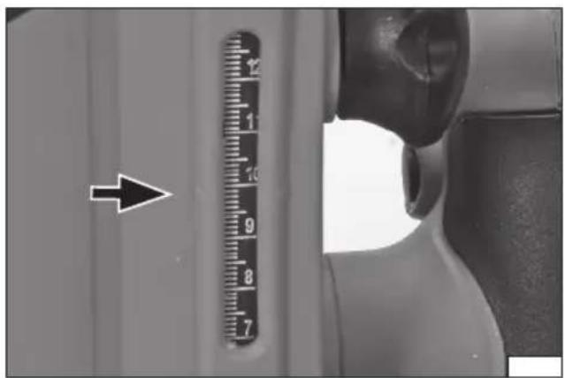
natural_image
Close-up of a mechanical component with arrows indicating direction, no visible text or symbols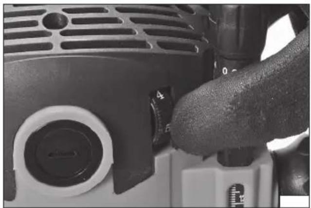
natural_image
Close-up of a hand operating a precision measuring instrument with a tool handle (no visible text or symbols)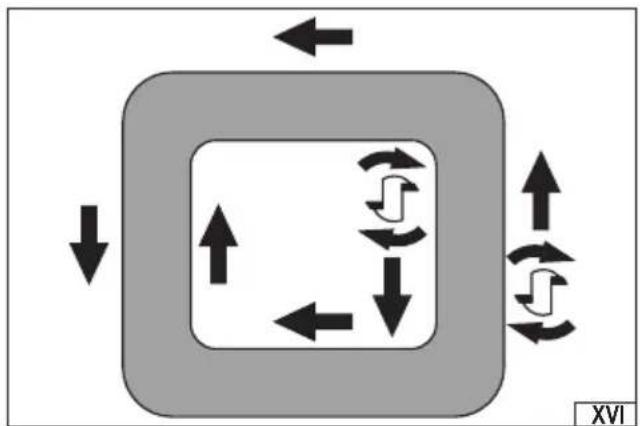
flowchart
graph TD
    A["Input"] --> B["Process Block"]
    B --> C["Output"]
    style A fill:#f9f,stroke:#333
    style B fill:#ccf,stroke:#333
    style C fill:#cfc,stroke:#333
    note1["↑"] --> B
    note2["↓"] --> B
    note3["↔"] --> B
    note4["↔"] --> B
    note5["↔"] --> B
    note6["↔"] --> B
    note7["↔"] --> B
    note8["↔"] --> B
    note9["↔"] --> B
    note10["↔"] --> B
    note11["↔"] --> B
    note12["↔"] --> B
    note13["↔"] --> B
    note14["↔"] --> B
    note15["↔"] --> B
    note16["↔"] --> B
    note17["↔"] --> B
    note18["↔"] --> B
    note19["↔"] --> B
    note20["↔"] --> B
    note21["↔"] --> B
    note22["↔"] --> B
    note23["↔"] --> B
    note24["↔"] --> B
    note25["↔"] --> B
    note26["↔"] --> B
    note27["↔"] --> B
    note28["↔"] --> B
    note29["↔"] --> B
    note30["↔"] --> B
    note31["↔"] --> B
    note32["↔"] --> B
    note33["↔"] --> B
    note34["↔"] --> B
    note35["↔"] --> B
    note36["↔"] --> B
    note37["↔"] --> B
    note38["↔"] --> B
    note39["↔"] --> B
    note40["↔"] --> B
    note41["↔"] --> B
    note42["↔"] --> B
    note43["↔"] --> B
    note44["↔"] --> B
    note45["↔"] --> B
    note46["↔"] --> B
    note47["↔"] --> B
    note48["↔"] --> B
    note49["↔"] --> B
    note50["↔"] --> B
natural_image
Close-up of hands operating a mechanical tool on a metal frame (no visible text or symbols)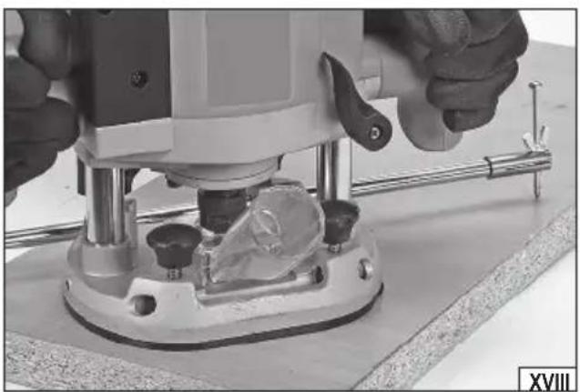
natural_image
Close-up of hands operating a mechanical tool on a workbench, no visible text or symbolsPL
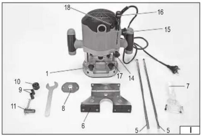
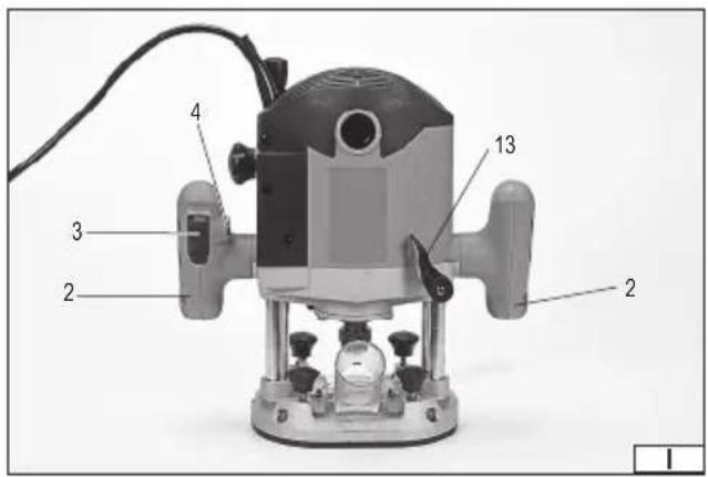
-
sole plate
-
handle
-
on/off switch
-
on/off switch lock
-
guide rod
-
retaining plate
-
dust extraction adapter
-
template plate
-
reduction sleeve
-
cutter handle nut
-
clamp with a needle
-
cutter
-
stroke lock lever
-
depth gauge lock knob
-
depth gauge controller
-
micrometer knob
-
rotary retaining plate
-
speed controller
-
template
20.workpiece
D
Read the operating instruction
Wear protective goggles
Schutzbrille tragen
Wear hearing protectors
Gehörschutz tragen
This symbol indicates that waste electrical and electronic equipment (including batteries and storage cells) cannot be disposed of with other types of waste. Waste equipment should be collected and handed over separately to a collection point for recycling and recovery, in order to reduce the amount of waste and the use of natural resources. Uncontrolled release of hazardous components contained in electrical and electronic equipment may pose a risk to human health and have adverse effects for the environment. The household plays an important role in contributing to reuse and recovery, including recycling of waste equipment. For more information about the appropriate recycling methods, contact your local authority or retailer.
WYPOSAŻENIE PRODUKTU
PRODUCT CHARACTERISTICS
The plunge router is used to process wood and wood-based materials using shank cutters. The plunge router is equipped with guides to facilitate straight and curved cutting. The possibility of easily connecting the dust extraction system makes work safer. The correct, reliable and safe operation of the tool depends on its proper use, therefore:
Read and keep this entire manual before the first use of the tool.
The tool supplier shall not be liable for any damage resulting from failure to comply the safety instructions and recommendations specified in this manual.
ACCESSORIES
The tool is delivered complete but requires preparation before beginning operation. The plunge router is supplied with guides, dust extraction connection and a sleeve for mounting cutters with a smaller handle diameter. Cutters are not supplied with the tool.
TECHNICAL DATA
| Parameter Unit Value | ||
| Catalogue No. YT-82380 | ||
| Power supply voltage [V~] 220 - 240 | ||
| Power frequency [Hz] 50 | ||
| Rated power [W] 2100 | ||
| Rated speed [min] | -1 8000 - 23500 | |
| Chuck size [mm] | 8 / 12 | |
| Cutting unit stroke | [mm] | 55 |
| Insulation class | II | |
| Protection rating | IP20 | |
| Noise level | ||
| - sound pressure LmA ± KpA | [dB (A)] | 94 ± 3 |
| - sound power LwA ± KwA | [dB (A)] | 105 ± 3 |
| Vibration aη ± K | [m/s2] | 3.41 ± 1.5 |
| Weight | [kg] | 6.6 |
The declared noise emission values have been measured using the standard test method and can be used to compare one tool to another. The declared noise emission values can also be used for preliminary exposure assessment.
Warning! Noise emissions during the correct operation of a power tool may differ from the declared values depending on the manner in which the tool is used, in particular the type of the workpiece.
Warning! Operator protection measures must be determined based on an approximation of exposure under current conditions of use. All stages of the work cycle must be taken into account. In addition to the working time, other factors must be taken into account, such as the time when the tool is switched off and when it is idle.
GENERAL WARNINGS FOR THE SAFETY OF POWER TOOLS
Warning! Read all safety warnings, illustrations and specifications provided with this power tool. Failure to do so may result in electric shock, fire or serious injury.
Keep all warnings and instructions for future reference.
The term "power tool" used in warnings applies to all tools driven by power both wired and wireless.
Workplace safety
Keep the workplace well-lit and clean. Disorder and poor lighting can be causes of accidents.
Do not work with power tools in an environment with an increased risk of explosion, containing flammable liquids, gases or vapors. Power tools generate sparks that can ignite dust or fumes.
Children and third persons should not be allowed to enter the workplace. Loss of concentration can result in loss of control.
Electrical safety
The plug of the electric cable must match the power socket. You must not modify the plug in any way. Do not use any plug adapters with earthed power tools. An unmodified plug that fits the outlet reduces the risk of electric shock.
Avoid contact with earthed surfaces such as pipes, radiators and coolers. Grounding the body increases the risk of electric shock.
GB
Do not expose power tools to contact with atmospheric precipitation or moisture. Water and moisture that gets inside the power tool increases the risk of electric shock.
Do not overload the power cable. Do not use the power cord to carry, pull or unplug the power plug from the power outlet.
Avoid contact of the power cable with heat, oils, sharp edges and moving parts. Damage or entanglement of the power cord increases the risk of electric shock.
In the case of working outside closed rooms, use extension cords intended for work outside closed rooms. The use of an extension cord adapted for outdoor use reduces the risk of electric shock.
When using a power tool in a humid environment is unavoidable as a protection against supply voltage use a residual current device (RCD). The use of RCD reduces the risk of electric shock.
Personal safety
Stay alert, pay attention to what you do and keep common sense while working with the power tool. Do not use a power tool when you are tired or under the influence of alcohol or medication. Even a moment of inattention while working can lead to serious personal injury.
Use personal protective equipment. Always wear eye protection. The use of personal protective equipment such as dust masks, anti-slip safety shoes, helmets and hearing protection reduce the risk of serious personal injury.
Prevent accidental operation. Make sure that the electric switch is in the “off” position before connecting to the power supply and / or battery, lifting or moving the power tool. Moving the power tool with the finger on the switch or powering the power tool, when the switch is in the “on” position can lead to serious injuries.
Before turning on the power tool remove any keys and other tools that were used to adjust it. The key left on the rotating parts of the power tool can lead to serious injuries.
Do not reach and do not lean too far. Keep the right attitude and balance all the time. This will allow easier control over the power tool in case of unexpected work situations.
Dress accordingly. Do not wear loose clothing or jewelry. Keep your hair and clothing away from moving parts of the power tool. Loose clothing, jewelry or long hair can be caught by moving parts.
If the devices are fitted for the connection of dust extraction or dust collection, make sure that they are connected and used properly. The use of dust extraction reduces the risk of dust hazards.
Do not let the experience acquired from frequent use of the tool resulted in carelessness and ignoring safety rules.
Carefree action can cause serious injuries in a fraction of a second.
Use and care of the power tool
Do not overload the power tool. Use the power tool appropriate for the selected application. The right power tool will provide a better and safer job if used according to the designed load.
Do not use the power tool, if the electric switch does not allow switching on and off. Power tool, which cannot be controlled by means of a power switch is dangerous and must be returned for repair.
Disconnect the plug from the power socket and / or remove the battery if it is detachable from the power tool before adjusting, changing accessories or storing the tool. Such preventive measures will allow you to avoid accidentally turning on the power tool.
Keep the tool out of the reach of children, do not let people who do not know how to operate the power tool or these instructions use a power tool. Power tools are dangerous in the hands of untrained users.
Maintain power tools and accessories. Check the tool for mismatches or jams of moving parts, damage to parts and any other conditions that may affect the operation of the power tool. Damage must be repaired before using the power tool. Many accidents are caused by incorrectly maintained tools.
Keep cutting tools sharp and clean. Properly maintained cutting tools with sharp edges are less prone to jamming and are easier to control when working.
Use power tools, accessories and inserted tools etc. in accordance with these instructions, taking into account the type and conditions of work. The use of tools for work other than designed is likely to result in a dangerous situation.
Handles and gripping surfaces must be dry, clean and free from oil and grease. Slippery handles and gripping surfaces do not allow for safe operation and control of the tool in dangerous situations.
Repairs
Repair the power tool only in authorized facilities using only original spare parts. This ensures proper operation safety of the power tool.
ADDITIONAL SAFETY WARNINGS FOR ROUTERS
Hold the tool by the insulated surfaces of the handle, as the tool may come into contact with its own power cord. Cutting the “live” cable may cause the metal parts of the tool to become “live” and electrocute the operator.
Use clamps or other appropriate means to secure and hold the workpiece on a stable platform. Holding the workpiece with your hands or other parts of your body will cause instability and can lead to loss of control.
GB
The purpose of the tool
The tool is used for processing wood by means of shank cutters guided from the top of the workpiece along its surface. It is also possible to process wood-based materials such as MDF, chipboard, plywood, etc.
The processing of materials other than wood and wood-based materials, such as plastics or metals, is prohibited. Do not use the tool as a stationary tool or as a drive for other tools. The user is liable for all damage resulting from improper use of the tool.
Residual risks
Even if the tool is used correctly, there are residual risks which cannot be avoided. The following hazards arise from the construction and use of the tool: contact with the rotating cutting tool; ejection of the inserted tool or its parts; ejection of dust and pieces of wood; inhalation of dust generated during work; hearing damage if no hearing protection is used; electric shock when touching non-insulated parts of the tool. Failure to follow the instructions in the manual may be the cause of other hazards resulting from improper use.
Additional safety instructions
Always hold the tool by the insulated handles when working. The inserted tool may come into contact with the tool's power cord or with another hidden "live" cord. Such contact may cause uninsulated parts of the tool to become live and may electrocute the operator. Always attach the workpieces to a stable base, e.g. a work table. Never hold the workpiece with your hands, legs or other body parts. The correct clamping of the workpiece will reduce the risk of losing control of the tool and body contact with moving parts of the tool. When processing long workpieces, support them near the machining point and near their ends. Long elements tend to bend under their own weight. The supports must be positioned so that the bending parts of the components do not catch the tool. Use only cutters with the diameter of the handles specified in the manual. Do not rework the cutter handle to fit the tool socket. Use the sleeve and nut to match the diameter of the handle. Before installing the cutter, make sure that its speed is greater than or equal to the speed of the tool.
Processing some materials can generate dust which can be harmful if inhaled. Always use dust masks during operation. You should also connect the tool to the dust extraction system whenever possible.
Check the tool and the inserted tool for damage before each use. If you notice any damage, do not begin work until the damage has been repaired. Pay special attention to the power cord. The damaged power cord cannot be repaired and must be replaced entirely. Replacement must be carried out at an authorised service centre. Always pull the power cord by the plug when unplugging it from the socket, never by the cord.
Wear personal protection equipment during work: eye protection, hearing protection, dust mask, protective clothing with long sleeves and legs, protective gloves, helmet and footwear with anti-slip soles. Long hair should be tied up.
All activities related to the assembly and adjustment must be carried out with the tool power supply disconnected. The tool power cord must be unplugged from the socket. Make sure the on/off switch is in the "off" position before connecting the tool to the power supply.
Before using the cutter, make sure that the cutting edges are free from damage and properly sharpened. Damaged cutting edges can cause the cutter to jump away from the workpiece, cause uneven work results and the cutter to crack. Imperfect edges will require the cutter to be pressed with greater force against the workpiece, which can cause the workpiece to burn and also cause the cutter to crack.
Do not use cutters with a larger diameter than the dimensions of the opening in the base. After mounting the cutter in the plunge router spindle it should not block the lowering and lifting of the plunge router housing.
TOOL OPERATION
Preparing for operation
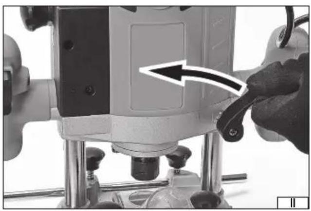
Take the tool and accessories out of the packaging and remove all its parts.
Due to the reduced size of the packaging, the plunge router is delivered set in the lowest position. Place the plunge router on its sole plate and then hold the top of the housing with one hand and using the other hand, turn the stroke lock lever counter-clockwise (II). The springs in the brackets will raise the plunge router housing. Use your hand on the top of the housing to generate slight resistance so that lifting is not too abrupt.
Fully unwind the power cord.
Connecting the dust extraction system adapter
The dust extraction system adapter consists of two components: a transparent connection for the dust extraction system and a metal mounting plate. The dust extraction system can only be used for cutters with a diameter smaller than that of the opening in the mounting plate.
The adapter shall be mounted to the opening in the upper part of the sole plate so that the dust extraction system connection is directed away from or towards the operator (III). Fasten the adapter with screws. Do not tighten the screws too much to avoid damaging the adapter.
An industrial vacuum cleaner can be used as a dust extraction system. It is not recommended to use a household vacuum cleaner, which is not suitable for absorbing dust generated during wood processing and may be damaged during such work. Always connect a flexible hose to the tool connection, which allows the tool to operate freely. Position the hose so that it does not come
GB
into contact with the inserted tool during operation. If the diameter of the vacuum cleaner hose differs from the diameter of the connection, use the adapter (available separately).
Installing the template plate
The template plate allows the cutting of the shape on the basis of the template. The plate should be mounted from the bottom of the plunge router sole plate so that the sleeve in the centre of the plate faces downwards (IV). Place the dust extraction adapter on top of the sole plate and tighten the screws. Do not tighten the screws too much to avoid damaging the adapter. When guiding the plunge router, press the plate sleeve firmly against the template (V). The material cut out on the basis of the template will have dimensions slightly different from those of the template. This is because the diameter of the cutter must be smaller than the diameter of the sleeve of the template plate.
Cutter assembly and disassembly
Warning! Due to the risk of injury from sharp edges of the cutter, assembly must be carried out using protective gloves.
Select the cutter with the handle diameter listed in the technical data table. Press and hold the spindle lock button and unscrew the clamping nut (VI) using a wrench. If the diameter of the cutter handle is smaller than the sleeve inside the nut, use the supplied reduction sleeve (VII). The nut with the cutter should be screwed onto the spindle thread, then by pressing and holding the spindle lock, tighten the nut firmly and securely using a wrench (VIII).
To disassemble the cutter, follow the above procedure in the reverse order.
Mounting the parallel cutting guide
The guide makes it easy to cut straight edges or rebates. The guide consists of a retaining plate and two rods. Remove both screws at the ends of the rods completely. Then fix the rods to the retaining plate using screws (IX). Place the supplied flat and spring washers under the screw heads to prevent the screws from loosening due to vibrations during operation. The rods should face in the same direction as the retaining plate.
Insert the rods into the openings in the sole plate housing, then lock the guide position by tightening the screws in the sole plate (X).
Mounting the circular cutting guide
The guide makes it easy to cutting circles and curves. The guide consists of one rod and the clamp with a needle. Insert the rod through the openings in the sole plate of the plunge router and fix its position with screws. Slide the clamp with a needle onto the end of the rod without the screw and secure it by tightening the wing nut (XI). Adjust the position of the needle so that the sharp end provides reliable support when performing circular cutting. Always lock the position of the needle by tightening the wing nut.
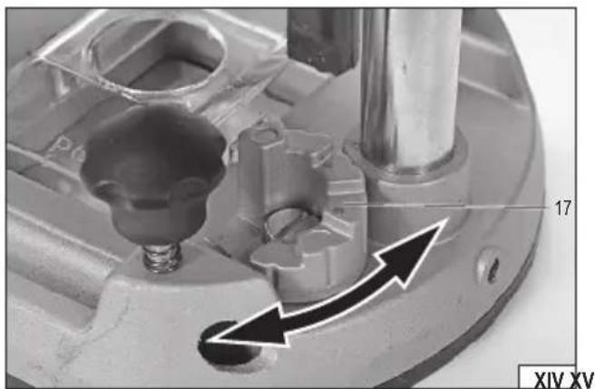
Setting the cutting unit stroke
The cutting unit stroke is used to set the cutting depth. Make sure that the stroke lock lever is not locked and that the plunge router housing can be moved freely in relation to the sole plate. Loosen the depth gauge lock knob. Set the depth gauge controller position by turning it (XII). The position can be read in the housing window (XIII). The depth gauge is also equipped with a micrometer knob, which enables precise setting of the cutting depth by means of an additional rod pulled out from the depth gauge. The rotation of the knob is scaled in millimetres of the length of the extension of the rod. The depth gauge rests on the rotary retaining plate located in the sole plate (XIV). The plate must be turned so that the desired cutting depth is set.
The plunge router housing in the lower position should be locked by turning the stroke lock lever clockwise as far as possible.
Speed adjustment (XV)
The plunge router speed can be adjusted smoothly within the range specified in the technical data table. The speed is set using the knob. The higher the visible number, the higher the speed. The speed must be selected according to the type of workpiece and the diameter of the cutter. The smaller the diameter of the cutter and the harder the wood, the higher the speed which can be set. Please note, however, that too high a speed can cause the workpiece to burn. It is recommended to carry out tests on waste material.
Warning! Do not change the speed setting while the tool is running under load.
Starting and stopping the cutter
Before starting the plunge router, hold the plunge router with both hands on the handles and make sure that the cutter does not come into contact with any objects. The plunge router is started by pressing and holding the on/off switch. Hold the plunge router running for approx. 30 seconds before starting work. You can start working if no abnormal working symptoms are detected during this time, e.g. increased vibration, increased noise, suspicious smell or smoke coming from the tool.
The device is stopped by releasing the on/off switch. After releasing the on/off switch, the cutter will keep spinning for some time.
Wait for the cutter rotation to stop completely before putting the tool away.
The on/off switch has a safety lock to prevent unintentional pressing. Before pressing the on/off switch, press and hold the lock button, and then press the on/off switch. You do not need to hold down the lock button any longer.
Cutting (XVI)
The direction of rotation of the spindle is indicated by an arrow on the sole plate and on the housing. Cutting must be carried out
GB
counter-clockwise for external cutting and clockwise for internal cutting. This prevents the cutter from jumping and ensures a good cutting result.
The speed of the plunge router should be adjusted experimentally, it is recommended to carry out tests using waste made of the same material as the intended workpiece. The slower the speed, the better the cutting result. However, too slow a speed may cause the surface being cut to burn and leave permanent marks on it.
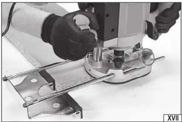
Cutting parallel to the edge (XVII)
In the case of such cutting, one of the edges of the workpiece shall be treated as the reference line for the routing of the plunge router. Set the cutting depth, set the guide for parallel cutting in the desired position, rest the guide plate against the edge of the workpiece and then move the plunge router so that the retaining plate always rests on the edge along its entire length. The cutter track will be parallel to the edge
Circular cutting (XVIII)
In this cutting process, the pivot point is used as the centre of the circle which determines the cutter track. Set the cutting depth, set the guide for circular cutting in the desired position and set the guide needle to the point which will be the centre of the circle. If possible, make a small indentation so that the needle blade has a better support. Then move the plunge router around a circle whose radius will be the distance between the axis of the needle and the axis of the cutter.
Tips for cutting
During cutting, the plunge router should be guided by a smooth motion at a uniform speed. The smoother the guiding motion, the higher the cutting quality.
Avoid hitting the workpiece with the cutter.
Allow the plunge router to reach the set speed and only then start cutting.
If cutting must be continued, enter the cutter into the track at full speed. This will prevent the cutter from being jammed in the workpiece.
MAINTENANCE AND OVERHAUL
CAUTION! Before carrying out any adjustment, servicing or maintenance work, unplug the tool from the power outlet. Having finished working with the workpiece/material, inspect the power tool for damage by visually inspecting the exterior and the body and the handles. Check the power cord and its rubber gland, the action of the ON/OFF switch, the vents for clogging, the motor brushes for sparking, the noise of the bearings and the drive transmission, and how the power tool starts and runs. During the warranty period, the user is not allowed to disassemble the tool or replace any components or parts, as this will void the warranty rights. Any irregularities found during overhaul or the operation signal the need for repair at a service centre. For this purpose, contact the manufacturer. Having finished your work, clean the housing, the vents, all switches, all handles and guards with compressed air (at 0.3 MPa maximum), a brush or a dry cloth. Do not use any chemicals or cleaners. Do not use sharp tools for cleaning. Remove the circular saw and clean the inside of the guards, the fixing of the circular saw, as well as the saw itself from dust and other impurities generated during operation. Clean handles, knobs and other adjusting parts with a dry, clean cloth.
PRODUKTBESCHREIBUNG
CARACTÉRISTIQUES DU PRODUIT
DECLARATION OF CONFORMITY
0122/YT-82380/EC/2022
We declare and guarantee with full responsibility that the following products:
Router; 220-240 V\~; 50 Hz; 2100 W; 8 / 12 mm; 8000 - 23500 min -1 ; item no. YT-82380
meet requirements of the following European Standards / Technical Specifications:
EN 62841-1:2015
EN 62841-2-17:2017
EN 55014-1:2006 + A1:2009 + A2:2011
EN 55014-2:2015
EN 61000-3-2:2014
EN 61000-3-3:2013
and fulfill requirements of the following European Directives:
2006/42/EC Machinery and safety elements
2014/30/EU Electromagnetic compatibility (EMC) Directive
2011/65/EU Restriction of the Use of Certain Hazardous Substances
Serial number: concern all serials numbers of item(s) mentioned in this declaration
The last two digits of the year in which the CE marking was affixed: 19
Year of production: 2022
The person authorized to compile the technical file:
Tomasz Zych
(Place and date of issue)

(Name and signature of authorized person)
TOYA S.A.
- PL
- D
- WYPOSAŻENIE PRODUKTU
- PRODUCT CHARACTERISTICS
- ACCESSORIES
- GENERAL WARNINGS FOR THE SAFETY OF POWER TOOLS
- Workplace safety
- Electrical safety
- GB
- Personal safety
- Use and care of the power tool
- Repairs
- ADDITIONAL SAFETY WARNINGS FOR ROUTERS
- The purpose of the tool
- Residual risks
- Additional safety instructions
- TOOL OPERATION
- Preparing for operation
- Connecting the dust extraction system adapter
- Installing the template plate
- Cutter assembly and disassembly
- Mounting the parallel cutting guide
- Mounting the circular cutting guide
- Setting the cutting unit stroke
- Speed adjustment (XV)
- Starting and stopping the cutter
- Cutting (XVI)
- Cutting parallel to the edge (XVII)
- Circular cutting (XVIII)
- Tips for cutting
- MAINTENANCE AND OVERHAUL
- PRODUKTBESCHREIBUNG
- CARACTÉRISTIQUES DU PRODUIT
- DECLARATION OF CONFORMITY
Brand : Yato
Model : YT-82380
Category : Milling machine