Multigym Plus G112X - Fitness Equipment BH FITNESS - Free user manual and instructions
Find the device manual for free Multigym Plus G112X BH FITNESS in PDF.
User questions about Multigym Plus G112X BH FITNESS
0 question about this device. Answer the ones you know or ask your own.
Ask a new question about this device
Download the instructions for your Fitness Equipment in PDF format for free! Find your manual Multigym Plus G112X - BH FITNESS and take your electronic device back in hand. On this page are published all the documents necessary for the use of your device. Multigym Plus G112X by BH FITNESS.
USER MANUAL Multigym Plus G112X BH FITNESS
natural_image
Modern MultiGym plus exercise machine with red seat and silver frame (no visible text or symbols)Instrucciones de montaje y utilización Instructions for assembly and use Instructions de montage et utilisation Montage und gebrauchsanleitung Instruções de montagem e utilização Istruzioni di montaggio e uso Montage-en gebruiksinstrukties
Fig.1
text_image
Technical diagram showing 28 numbered mechanical or structural components with labeled parts, likely for assembly or manufacturing purposes.Fig.2
text_image
Technical diagram showing various mechanical parts with numbered labels, likely for assembly or manufacturing purposes.Fig.3
text_image
11 76 70 76 80 10Fig.4
text_image
13 52 28 76 63 76 63Fig.5
text_image
Technical diagram of a mechanical testing apparatus with numbered components for identificationFig.6
text_image
2 80 76 10 70 76Fig.7
text_image
70 76 63 76 1 76 80 13 2Fig.8
text_image
Technical diagram of a mechanical lifting device with numbered components and labeled partsFig.9
text_image
Technical diagram of a mechanical exercise machine with numbered components and labeled partsFig.10
text_image
Technical diagram of a mechanical exercise machine with numbered components and labeled partsFig.11
text_image
Technical diagram of a mechanical exercise machine with numbered components and labeled partsFig.12
text_image
19 33 1 80 76 66 57 36 Fig.12B 5 80 76 65 38 Fig.12C 36 36A 83 42 82 14 Fig.12D 32 33 32 33 33 31 9 37 A1 C1 B1 D1 Fig.12A 17 57 U Fig.12EFig.13
text_image
Technical diagram of a fitness equipment machine with numbered components and labeled partsFig.14
text_image
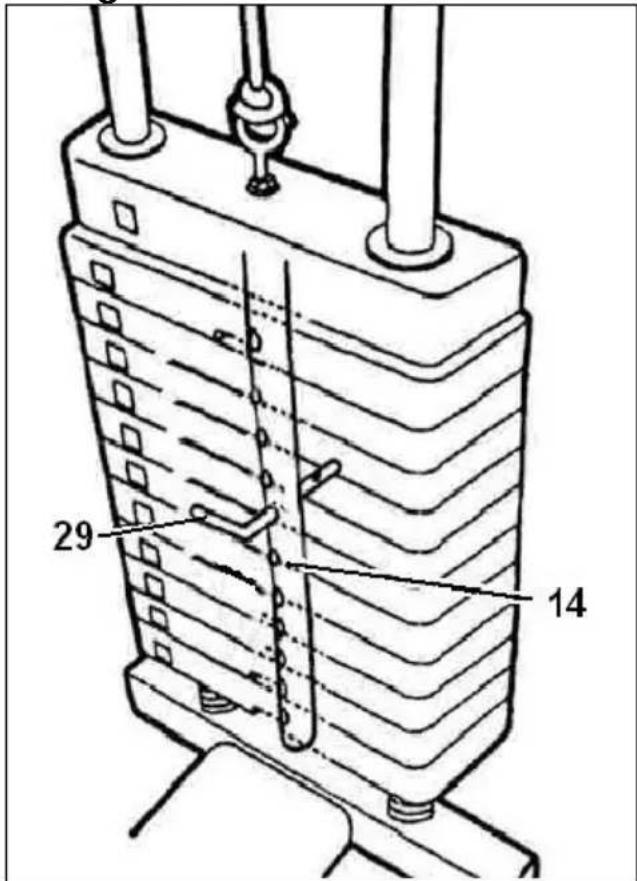
29 14Fig.15
natural_image
Technical line drawing of a mechanical device with labeled parts and directional arrow (no readable text or symbols)Fig.16
natural_image
Technical line drawing of a mechanical assembly with no visible text or symbolsEspañol
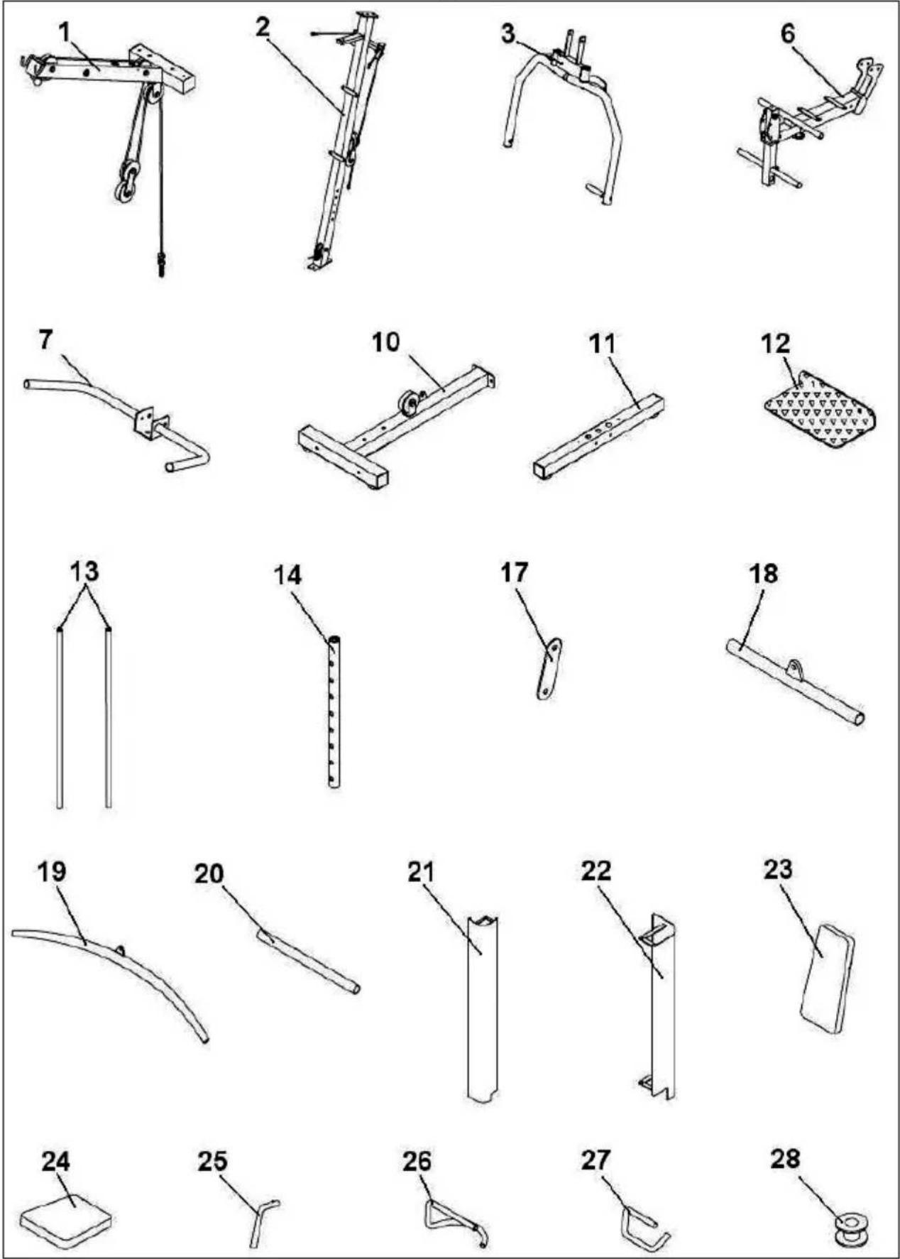
Take the unit out of its box and make sure that all of the pieces are there: The assistance of a second person is required for assembling this machine.
Fig.1.-
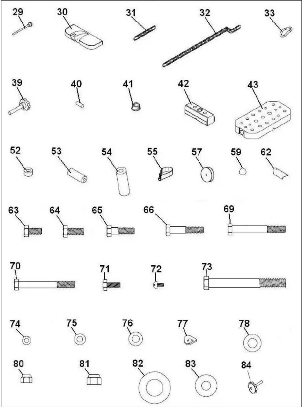
(1) Top body.
(2) Vertical mast.
(3) "Butterfly" arm rotation support.
(6) Seat support.
(7) Seat hand support.
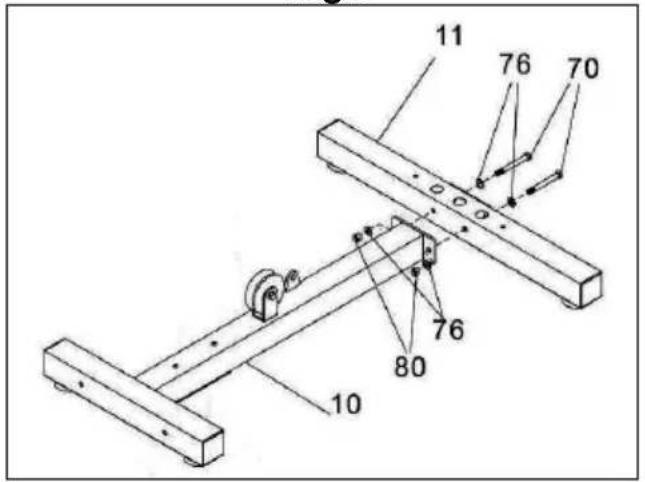
(10) Main post.
(11) Outer stabiliser.
(12) Feet support plate.
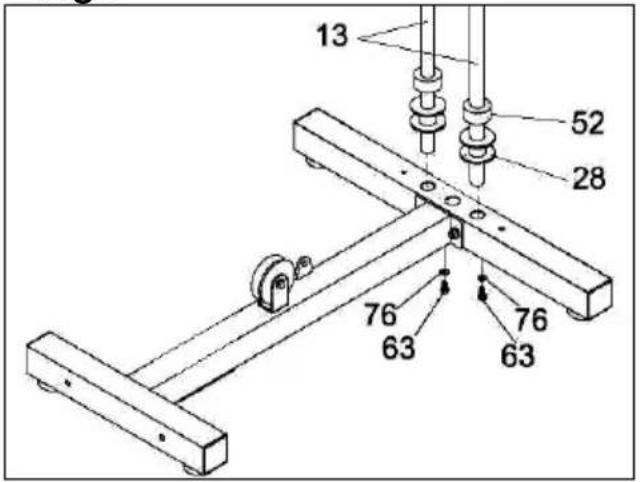
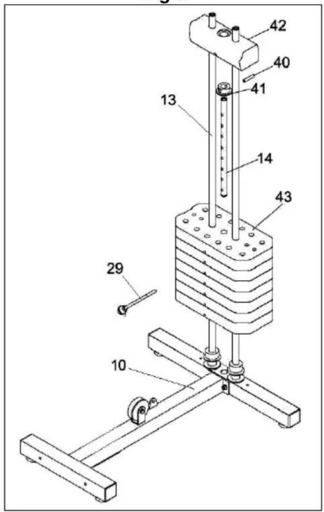
(13) Weight columns.
(14) Weight selector post.
(15) Butterfly bars.
(17) Linear pulley plates.
(18) Short exercise bar.
(19) Long exercise bar.
(20) Leg tube covers.
(21) Front right side panel.
(22) Rear left side panel.
(23) Backrest.
(24) Seat.
(25) Butterfly exercise selector.
(26) Seat locking pin.
(27) Leg lock pin.
(28) Bottom washer for weights.
(29) Weight selector.
(30) Top cover.
(31) Weight cable chain.
(32) Leg pull-up cable chain.
(33) Chain hook.
(39) Leg support adjustment knob.
(40) First weight lockpin.
(41) First weight holding collar.
(42) Top weight.
(43) Weight set.
(52) 45x45 tube cap.
(53) 25 diameter tube cap.
(54) 45 diameter tube cap.
(55) Arm stop protector.
(57) Large pulley.
(59) M-12 nut cover.
(62) Arm limit plate.
Fig.2.- NUTS & BOLTS.
(63) Bolts M-10x20.
(64) Bolts M-10x25.
(65) Bolts M-10x30.
(66) Bolts M-10x50.
(69) Bolts M-10x80.
(70) Bolts M-10x85.
(71) Bolts M-8x20.
(72) Bolts M-5x10.
(73) Bolts M-12x110.
(74) Flat washers M-5.
(75) Flat washers M-8.
(76) Flat washers M-10.
(77) Washers M-10.
(78) Flat washers M-12.
(79) Flat washers 19x40.
(80) Self-locking nut M-10.
(81) Self-locking nut M-12.
(82) Flat washers 26x46.
(83) Flat washers 13x32.
(84) Seat support adjustment knob.
ASSEMBLY.-
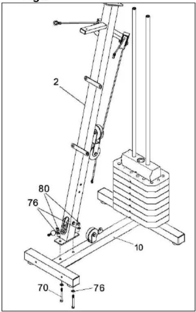
1- Place the base tube (1) close to the rear tube (11) Fig.3, fix with the screws (70), washers (76) and nuts (80) and tighten firmly.
FITTING THE WEIGHTS.-
2.- Fit the guide post (13) along with washers (28) and the bottom weight stops (52) as shown in Fig.4. 3.- Next, place the weights onto the guide post as shown in Fig.4, in correct alphabetical order with the letters facing the front of the machine, beginning with the letter "L".
4.- Now take the weight selector tube (14), Fig.4, and attach the holding collar (41) for the first weight and insert the lockpin (40). Fit the last weight (42) onto the bars, tighten the bolts (63) for the guide post (13) to the main body (10), as shown in Fig.5.
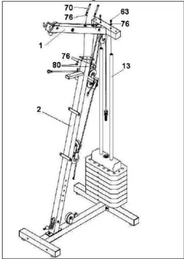
5.-Put the screws (70) into the screw holes so that they are in their correct position, without tightening Fig.6. Make sure the main structure (2) remains in a vertical position Fig.6.
6.-Fit the top body (1) Fig.7 onto the main body (2). Hand tighten the bolts (63) (70) as shown in Fig.7.
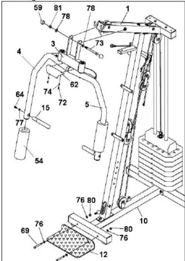
FITTING THE BUTTERFLY ARM SUPPORT.-
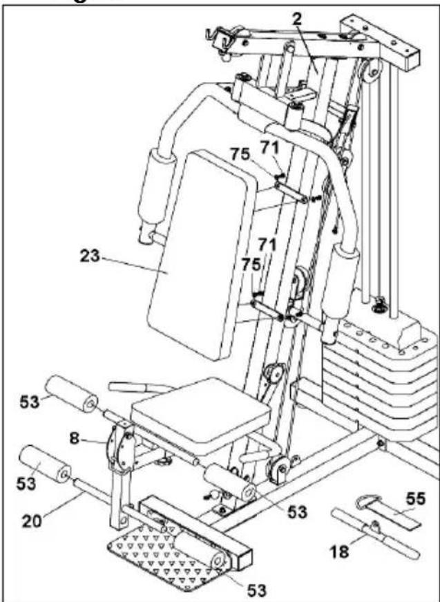
7.- Fit the butterfly arm support (3) into the top support (1), Fig.8. Insert bolt (73), along with washer (78) and nut (81), and tighten securely. Fit the nut cap (59). Next, place the feet support plate (12) close to the lower support (10) Fig.8. Fix the screws (69) with washers (76) and tighten the nuts (80).
FITTING THE ARM LIMIT PLATE.-
8.-Take the nuts, washers and bolts off the arm rotation support Fig.8. Next, fit the plate (62) with the logo facing outward and refit the bolts, washers and nut, tighten the bolts securely.
FITTING THE TOP FOAM COVERS.-
9.-Take the foam covers (54) and fit them onto the two BUTTERFLY bars, as shown in Fig.8. Now take the handle (15), remove the bolt and the washer Fig.8 and screw it on to the arms (left and right).
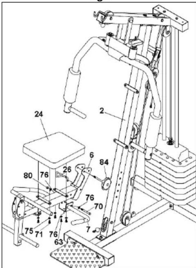
FITTING THE SEAT STRUCTURE.-
10.- Take the knob from the seat support (84). Position it on one of the two seat height setting holes Fig.9 and secure using the knob (84). Fit the seat locking pin (26).
FITTING THE HANDGRIP SUPPORT.-
11.- Fit the handgrip support (7) onto the tube for the seat frame (6), Fig.9. Next, insert bolt (70), flat washer (76) and tighten using nut (80).
FITTING THE SEAT.-
12.-Take the seat (24) and position it on the seat support Fig.9. Fit the bolts (71) with their washers (75) and tighten securely.
13.-Take the backrest (23) and position it against the central mast, as shown in Fig.10. Now use the bolts (71) and washers (75) to secure the backrest Fig.10.
FITTING THE BOTTOM FOAM COVERS.-
14.-First take the foam covers (53) and fit them onto the top rounded tubes for the leg support Fig.10. Now do the same for the bottom leg support foam covers (53).
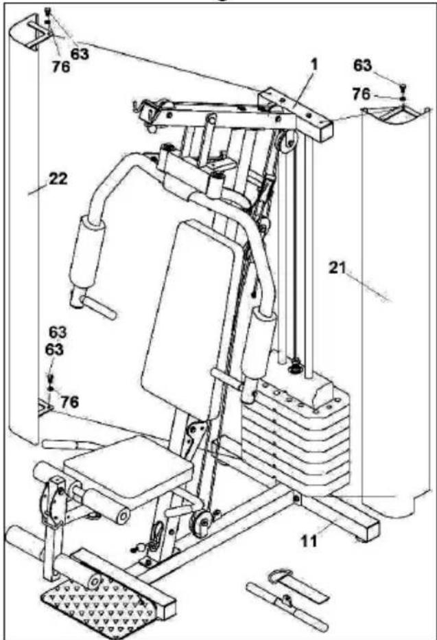
FITTING THE PANELS.-
15.-Position the left and right protection plates (22 and 21) onto the main frame (1), fitting the plate wedge into the accommodating groove in the base, then tighten screws (63) slightly in the upper part as shown in Fig.11.
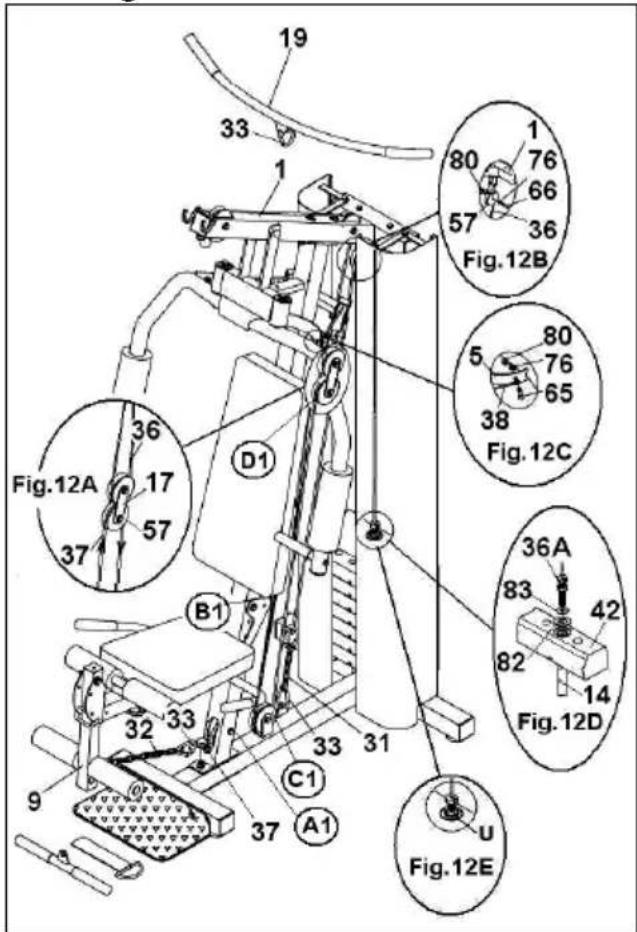
FITTING THE CABLE SYSTEM.-
◆ 16.- First check that the steel cables are correctly fitted into the pulleys that are supplied prefitted, following the arrows in Fig.12.
◆ Fit the plates (17) onto the pulleys (57) as shownh in Fig.12A.
◆ Position the upper body cable (36) onto pulley (57) Fig.12B, insert the pulley into the main body support (1), Fig.12B, and tighten using bolt (66), washer (76) and nut (80).
◆ Next, attach one end of cable (38) to the left arm plate for the Butterfly exercise, Fig.12C, fit bolt (65) with washers (76) and nut (80).
Do the same with the other end of cable (38) for the right Butterfly exercise arm.
- The weights have already been fitted into their housing in the previous assembly step.
❖ Lift the first weight (42) and fit the weight selector post (14), as shown in Fig.12D.
◆ Screw bolt (36A) into the selector post (14), when it is screwed in, lower the weight so that it rests on the other weights.
◆ Insert the weight selector pin (29) into the selector post (14), Fig.12, and tighten nut (U) securely, Fig.12E.
Take the end of the foot pull-up cable (37) and by following the arrows marked on the cable, Fig.12, pass it through the first pulley (A1), as shown in Fig.12.
◆ Next, pass the same tip through lower pulley (B1; C1) Fig.12.
◆ Continue passing the tip of the cable (37) through the third pulley (D1) Fig.12. Attach the end of the cable to the carabiner (33) and to chain (31), position it on the end joined to the support on the base, Fig.12.
Note: After a while you may notice that steel cable slackens a little due to the cable settling into position. To remedy this just tension the steel cable by changing the chain link (31).
17.- Fit the chain (32) onto the leg accessory hook (9) Fig.12, to be able to do the leg exercises.
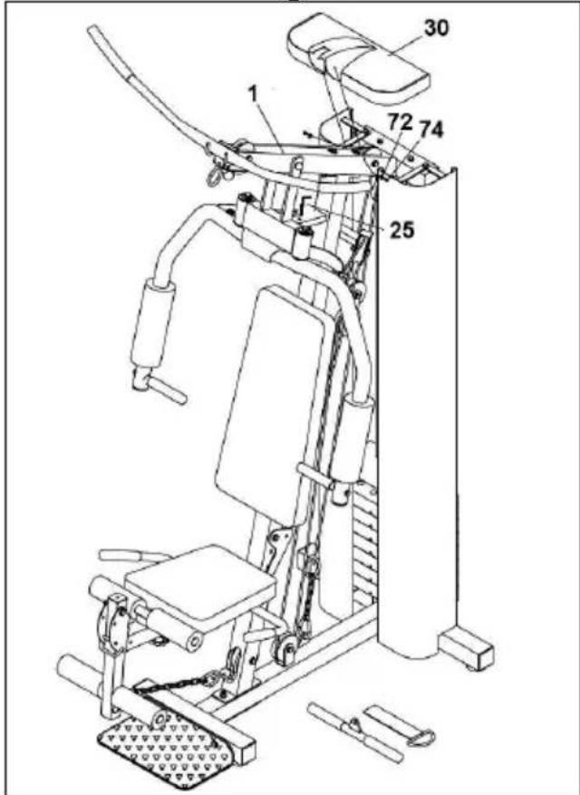
18.- Attach the top casing (30) fitting it over the upper body (1) so that it slots onto the main body Fig.13. Fasten on using screws (72).
19.- Set the selector (25) as shown in Fig.13 to be able to do the Butterfly exercise.
POSITIONING THE WEIGHT SELECTOR ROD.-
20.-Insert the weight selector (29) rod into the orifice of the weights required for the exercise, as shown in Fig.14. For optimum control of exercise conditions, the weights are already marked with letters.
By checking the equivalence charts on the bottom of the apparatus, you will be able to check the exercised strength as the meaning of each letter Fig.32 is expressed in kilograms and pounds.
FOLDING THE SEAT.-
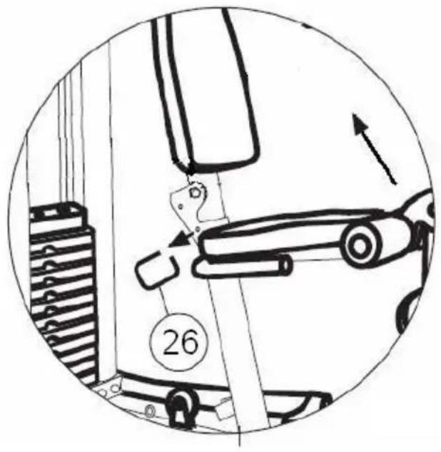
21.-To fold the seat, pull the safety rod (26) and lift it in the direction of the arrow as shown in Fig.15. The same rod is used to put the seat back up.
Note: The seat can be put into two different positions.
LEVELLING.-
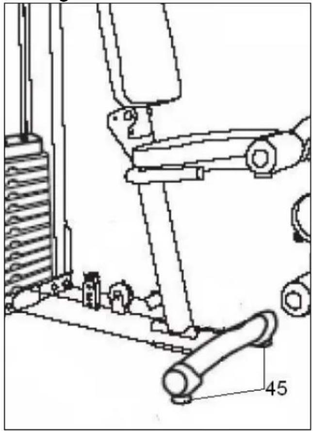
22.-Once it has been firmly positioned into place, check the base and ground level of the machine. Levelling can be improved by more or less swivelling the adjustable feet (45) Fig.16.
Do not hesitate to get touch with the Technical Assistance Service if you have any queries by phoning customer services (see last page in manual)
BH RESERVES THE RIGHT TO MODIFY THE SPECIFICATIONS OF ITS PRODUCTS WITHOUT PRIOR NOTICE
Français
1 MONTAGE.-
Monte as chapas (17) sobre as roldanas (57) da Fig.12A.
Fig.2.-MOEREN & SCHROEVEN
(63) Schroeven M-10x20.
(64) Schroeven M-10x25.
(65) Schroeven M-10x30.
(66) Schroeven M-10x50.
(69) Schroeven M-10x80.
(70) Schroeven Allen M-8x20.
(71) Schroeven M-8x20.
(72) Schroeven M-5x10.
(73) Schroeven M-12x110.
(74) Vlakke sluitringen M-5.
(75) Vlakke sluitringen M-8.
(76) Vlakke sluitringen M-10.
(77) Sluitringen M-10.
(78) Vlakke sluitringen M-12.
(79) Vlakke sluitringen M-19x40.
(80) Zelfborgende moer M-10.
(81) Zelfborgende moer M-12.
(82) Vlakke sluitringen M-26x46.
(83) Vlakke sluitringen M-13x32.
(84) Draaiknop zadelsteun.
MONTAGE.-
text_image
Technical diagram of a mechanical assembly with numbered components and labeled partsTo order replacement parts: State the part code and Quantity
e-mail: info@bhfitness.pt
BH SERVICE PORTUGAL
Tel.: +351 234 729 510
Fax: +351 234 729 519
e-mail: info@bhfitness.pt
BH GERMANY GmbH
Altendorfer Str. 526
45355 Essen
Tel: +49 201 450910-0
e-mail:
info@bhgermany.com
Toll free: +1 866 325 2339
service.uk@bhfitness.com
BH FITNESS ASIA
BH Asia Ltd.
No.80, Jhongshan Rd.,
Daya Dist.,
Taichung City 42841,
Taiwan. R.O.C.
Tel.: +886 4 25609200
Fax: +886 4 25609280
Block A, NO.68, Branch Lane
455, Lane 822,
Zhen Nan RD., Li Zi Yuan,
Putuo, Shanghai 200331, P.R.C.
Tel: +86-021-5284 6694
Fax:+86-021-5284 6814
e-mail: info@i-bh.cn
BH FITNESS FRANCE
SAV FRANCE
Tel : +33 0810 000 301
Fax : +33 0810 000 290
savfrance@bhfitness.com
BH SE RESERVA EL DERECHO A MODIFICAR LAS ESPECIFICACIONES DE SUS PRODUCTOS SIN PREVIO AVISO.
SPECIFICATIONS MAY BE CHANGED WITHOUT PRIOR NOTICE DUE TO OUR PROGRAMME OF CONTINUOUS PRODUCT DEVELOPMENT.
BH SE RÉSERVE LE DROIT DE MODIFIER LES SPECIFICATIONS DE SES PRODUITS SANS PRÉAVIS.