TT PRO G156 - Fitness Equipment BH FITNESS - Free user manual and instructions
Find the device manual for free TT PRO G156 BH FITNESS in PDF.
| Product Type | Multi-function strength training machine |
| Brand | BH Fitness |
| Model | TT PRO G156 |
| Category | Fitness Equipment |
| Primary Use | Full body strength training: chest, triceps, legs, glutes, abs, butterfly |
| Structure | Steel with guide tubes for dumbbells |
| Included Accessories | Long bar, short bar, pulleys, cables, seat, backrest, headrest, foam pads, supports |
| Weight System | Uses dumbbells with selector (dumbbells not included) |
| Assembly | Required, strongly recommended with two people |
| Number of Parts | Approximately 150 components (frame, screws, cables, foam pads) |
| Adjustments | Seat height, backrest position, leg support, headrest |
| Routine Maintenance | Check cable tension and tighten screws after use |
| Safety | Check all fastenings before use; use on a flat floor |
| Spare Parts | Available through after-sales service (provide part code and quantity) |
| Warranty | Contact BH Fitness customer service |
| Provided Manual | User and assembly manual in French (51 pages) |
| Country of Origin | Spain (BH Fitness brand) |
Frequently Asked Questions - TT PRO G156 BH FITNESS
User questions about TT PRO G156 BH FITNESS
0 question about this device. Answer the ones you know or ask your own.
Ask a new question about this device
Download the instructions for your Fitness Equipment in PDF format for free! Find your manual TT PRO G156 - BH FITNESS and take your electronic device back in hand. On this page are published all the documents necessary for the use of your device. TT PRO G156 by BH FITNESS.
USER MANUAL TT PRO G156 BH FITNESS
text_image
Pro training station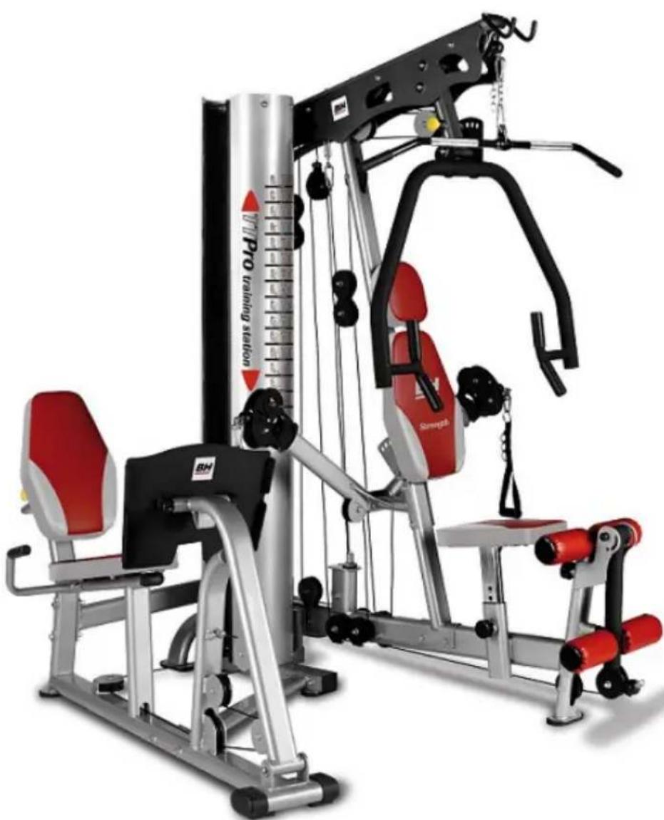
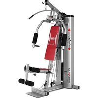
natural_image
Modern gym machine with red and silver seats, no visible text or symbols on the equipment bodytext_image
Technical diagram of 19 mechanical components with numbered labels for identificationFig.2
text_image
20 21 22 23 24 25 26 27 28 29 30 31 140 33 34 139 35 36 37 38 39 40 41 133Fig.3
text_image
42 43 44 141 46 49 142 53 54 57 58 59 64 65 67 68 79 83 85 91Fig.4
bar
| Number | Value | | ------ | ----- | | 98 | 98 | | 99 | 99 | | 100 | 100 | | 101 | 101 | | 102 | 102 | | 103 | 103 | | 104 | 104 | | 105 | 105 | | 106 | 106 | | 107 | 107 | | 108 | 108 | | 110 | 110 | | 111 | 111 | | 109 | 109 |Fig.5
text_image
73 112 113 114 115 116 117 118 119 120 121 122 123 124 125 126 127 128Fig.6
text_image
Technical diagram of a mechanical linkage system with numbered components and assembly detailsFig.7
text_image
Technical diagram of a mechanical assembly with numbered components and labeled partsFig.8
text_image
35 105 121 121 126 4 121 109 1Fig.9
text_image
141 142 53 35 85 140 85 140 35Fig.10
Fig.11
text_image
Technical diagram of a mechanical lifting device with numbered components and labeled partsFig.12
text_image
Technical diagram of a mechanical lifting device with numbered components for identificationFig.13

text_image
Technical diagram of a mechanical device with numbered components and labeled parts, likely for assembly or manufacturing documentation.Fig.14
text_image
Technical diagram of a mechanical assembly with numbered components and labeled partsFig.15
text_image
Technical diagram of a mechanical device with numbered components labeled 7, 111, and 34.Fig.16
text_image
Technical diagram of a mechanical lifting device with labeled components and exploded view detailsFig.17
text_image
Technical diagram of a mechanical assembly with numbered components for identificationFig.18
text_image
Technical diagram of a mechanical lifting device with labeled components and numbered partsFig.19
text_image
Technical diagram of a mechanical lifting device with labeled components and numbered partsFig.20
text_image
Technical diagram of a mechanical assembly with numbered components and labeled partsFig.21

text_image
Technical diagram of a mechanical device with numbered components and labeled partsFig.22
text_image
Technical diagram of a mechanical lifting device with numbered components for identificationFig.23
text_image
Technical diagram of a mechanical exercise machine with numbered components and labeled partsFig. 24
text_image
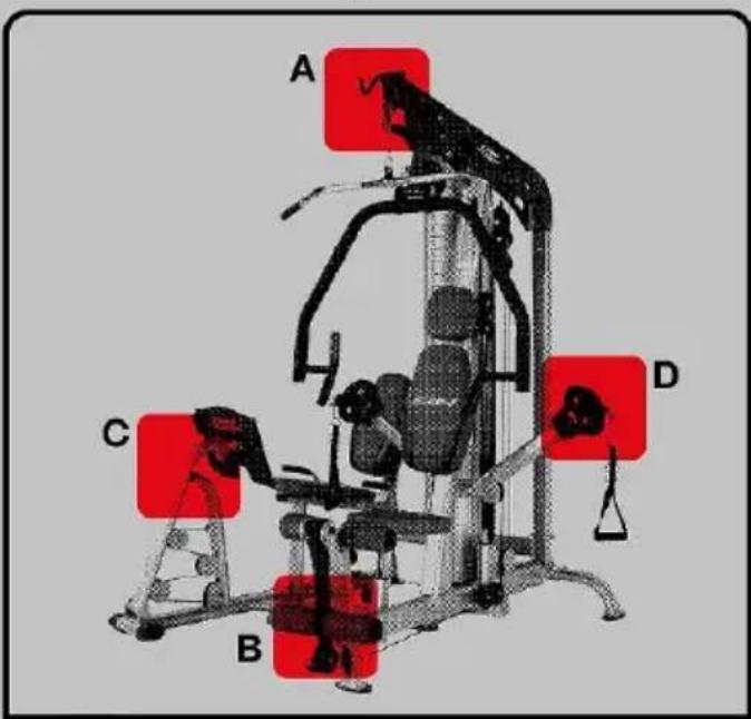
A C B D| Weight | A | B | C | D | ||||
| kg. | lb | kg. | lb | kg. | lb | kg. | lb | |
| A | 6 | 14 | 6 | 14 | 3 | 6 | 12 | 26 |
| B | 12 | 26 | 12 | 26 | 6 | 14 | 18 | 40 |
| C | 18 | 40 | 18 | 40 | 9 | 20 | 24 | 52 |
| D | 24 | 54 | 24 | 54 | 12 | 26 | 30 | 66 |
| E | 30 | 66 | 30 | 66 | 15 | 32 | 36 | 80 |
| F | 36 | 80 | 36 | 80 | 18 | 40 | 42 | 92 |
| G | 42 | 94 | 42 | 94 | 21 | 46 | 48 | 106 |
| H | 48 | 106 | 48 | 106 | 24 | 52 | 54 | 118 |
| I | 52 | 116 | 52 | 116 | 27 | 60 | 60 | 132 |
| J | 58 | 128 | 58 | 128 | 30 | 66 | 66 | 146 |
| K | 64 | 140 | 64 | 140 | 33 | 72 | 72 | 158 |
| L | 70 | 154 | 70 | 154 | 36 | 80 | 78 | 172 |
| M | 76 | 168 | 76 | 168 | 39 | 86 | 84 | 184 |
| N | 82 | 180 | 82 | 180 | 42 | 92 | 90 | 198 |
| O | 88 | 194 | 88 | 194 | 45 | 100 | 96 | 212 |
| P | 94 | 206 | 94 | 206 | 48 | 106 | 102 | 224 |
| Q | 100 | 220 | 100 | 220 | 51 | 112 | 108 | 238 |
| R | 106 | 234 | 106 | 234 | 54 | 118 | 114 | 250 |
| S | 112 | 248 | 112 | 248 | 57 | 126 | 120 | 264 |
| T | 120 | 260 | 120 | 260 | 60 | 130 | 126 | 276 |
Español
The assistance of a second person is required for assembling this machine.
Take the unit out of its box and make sure that all of the pieces are there:
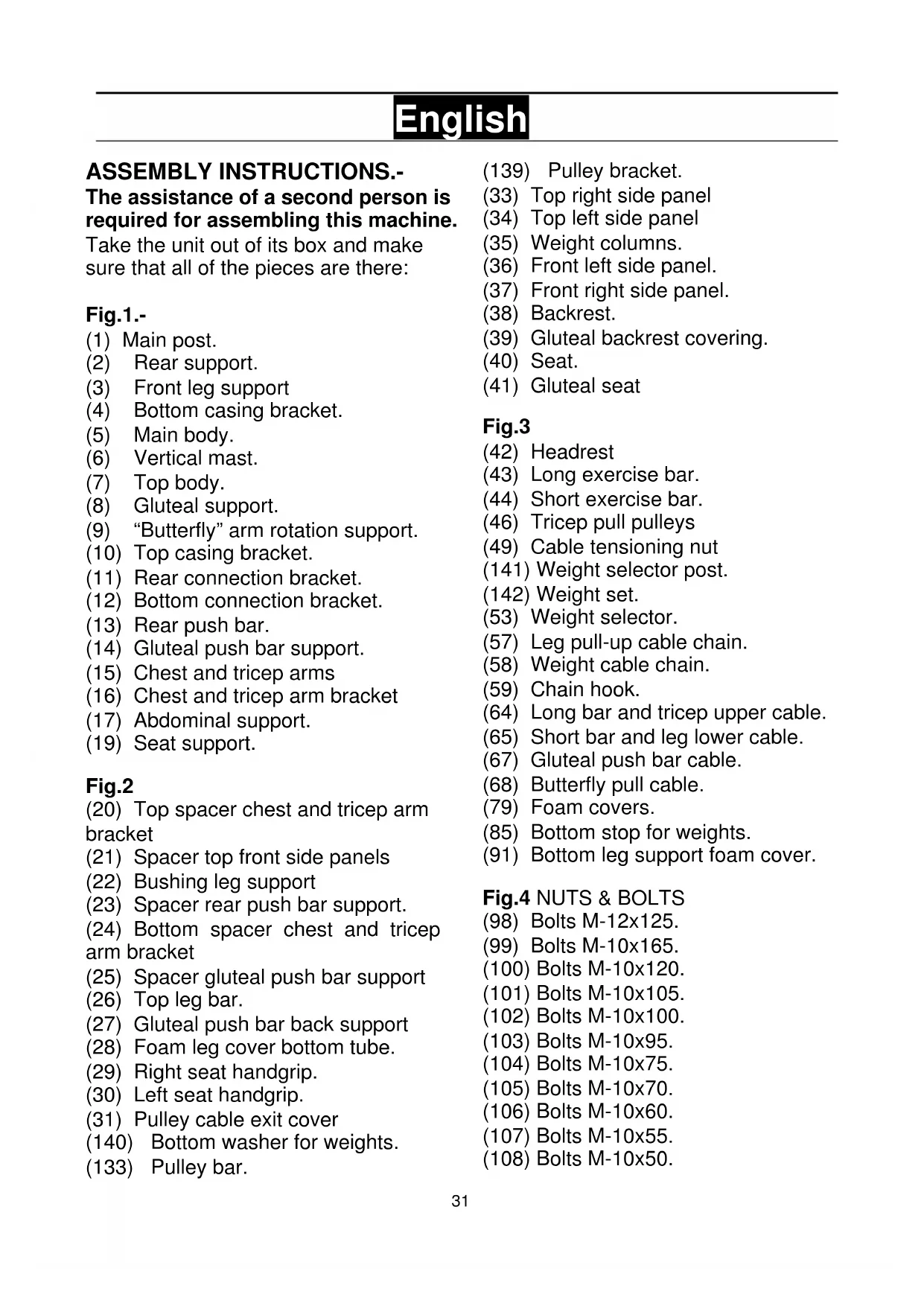
Fig.1.-
(1) Main post.
(2) Rear support.
(3) Front leg support
(4) Bottom casing bracket.
(5) Main body.
(6) Vertical mast.
(7) Top body.
(8) Gluteal support.
(9) "Butterfly" arm rotation support.
(10) Top casing bracket.
(11) Rear connection bracket.
(12) Bottom connection bracket.
(13) Rear push bar.
(14) Gluteal push bar support.
(15) Chest and tricep arms
(16) Chest and tricep arm bracket
(17) Abdominal support.
(19) Seat support.
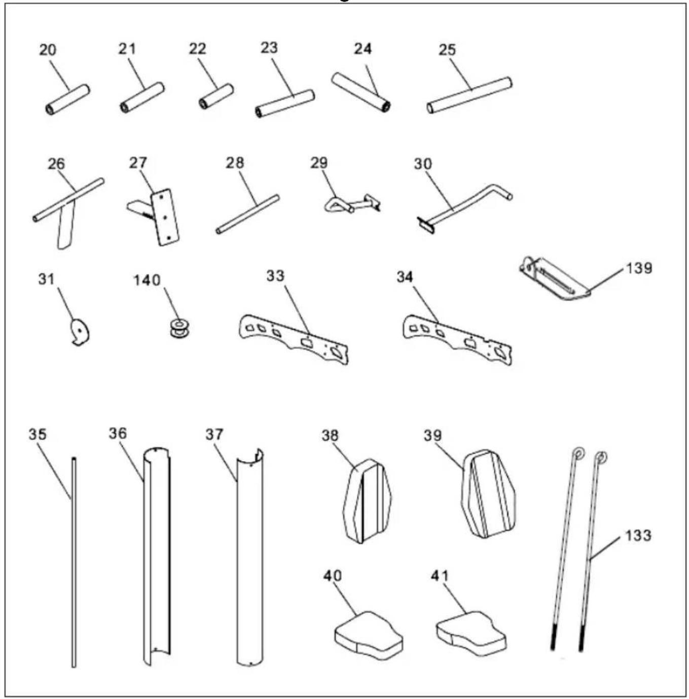
Fig.2
(20) Top spacer chest and tricep arm bracket
(21) Spacer top front side panels
(22) Bushing leg support
(23) Spacer rear push bar support.
(24) Bottom spacer chest and tricep arm bracket
(25) Spacer gluteal push bar support
(26) Top leg bar.
(27) Gluteal push bar back support
(28) Foam leg cover bottom tube.
(29) Right seat handgrip.
(30) Left seat handgrip.
(31) Pulley cable exit cover
(140) Bottom washer for weights.
(133) Pulley bar.
(139) Pulley bracket.
(33) Top right side panel
(34) Top left side panel
(35) Weight columns.
(36) Front left side panel.
(37) Front right side panel.
(38) Backrest.
(39) Gluteal backrest covering.
(40) Seat.
(41) Gluteal seat
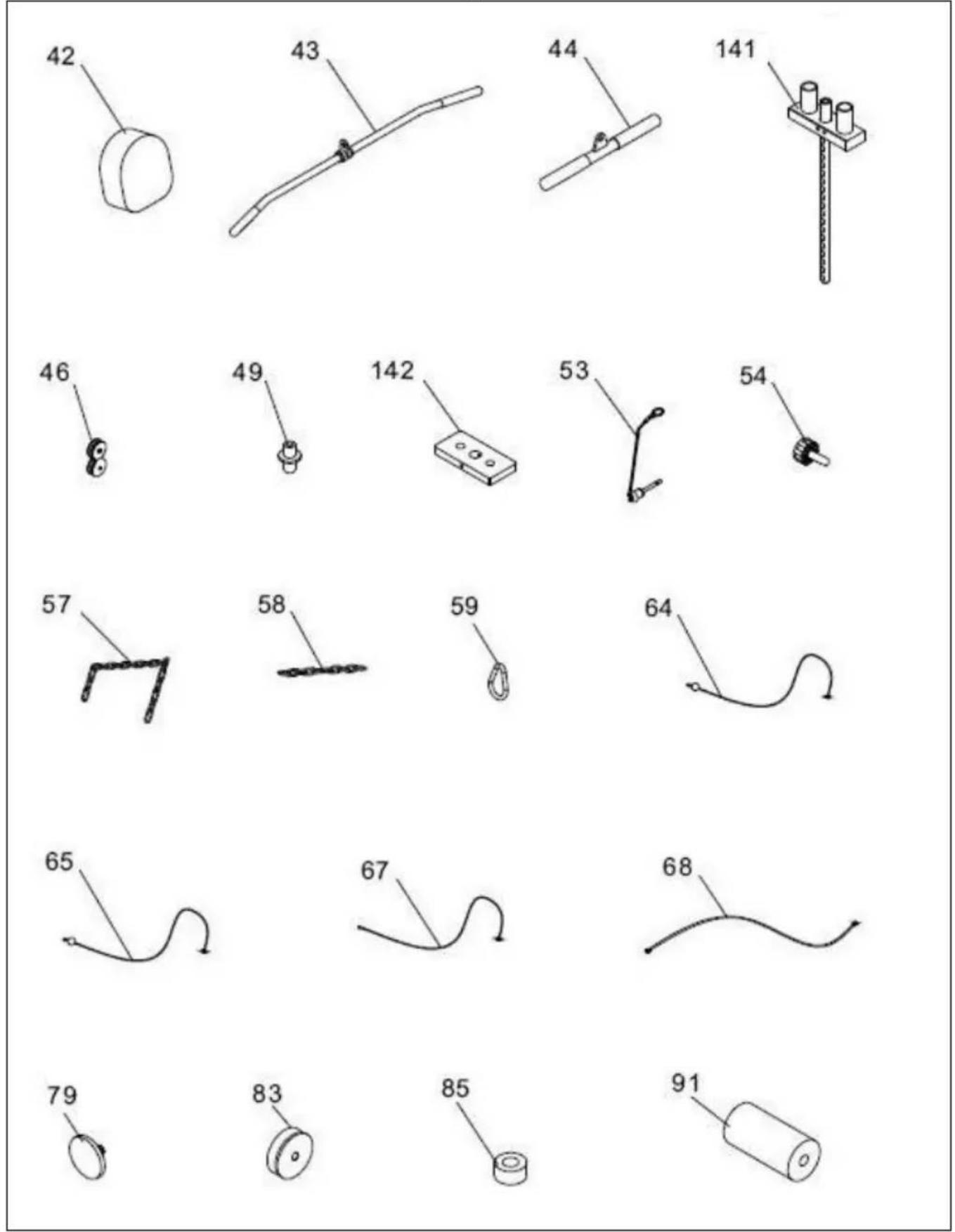
Fig.3
(42) Headrest
(43) Long exercise bar.
(44) Short exercise bar.
(46) Tricep pull pulleys
(49) Cable tensioning nut
(141) Weight selector post.
(142) Weight set.
(53) Weight selector.
(57) Leg pull-up cable chain.
(58) Weight cable chain.
(59) Chain hook.
(64) Long bar and tricep upper cable.
(65) Short bar and leg lower cable.
(67) Gluteal push bar cable.
(68) Butterfly pull cable.
(79) Foam covers.
(85) Bottom stop for weights.
(91) Bottom leg support foam cover.
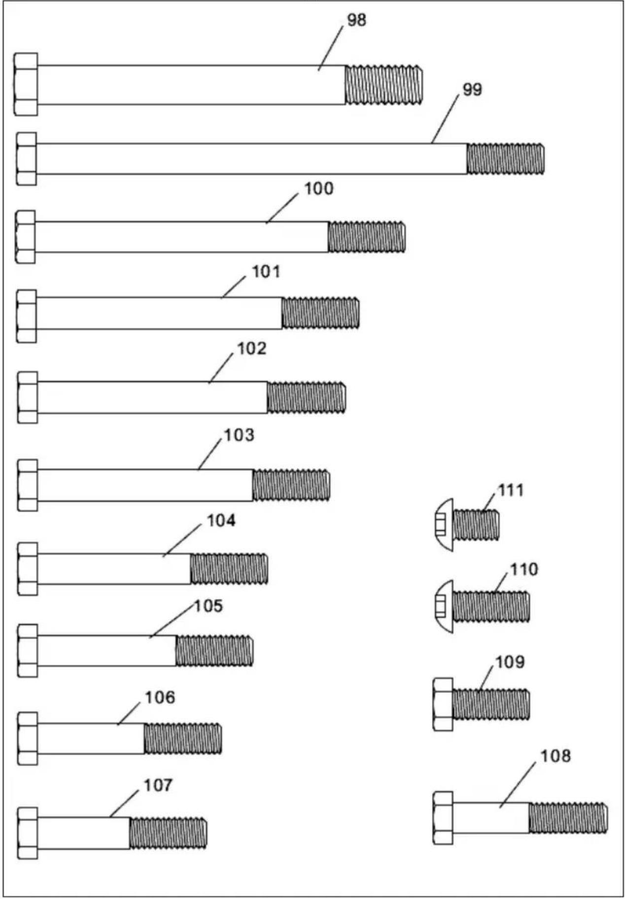
Fig.4 NUTS & BOLTS
(98) Bolts M-12x125.
(99) Bolts M-10x165.
(100) Bolts M-10x120.
(101) Bolts M-10x105.
(102) Bolts M-10x100.
(103) Bolts M-10x95.
(104) Bolts M-10x75.
(105) Bolts M-10x70.
(106) Bolts M-10x60.
(107) Bolts M-10x55.
(108) Bolts M-10x50.
(109) Bolts M-10x25.
(110) Allen screw M-10x25.
(111) Allen screw M-10x15.
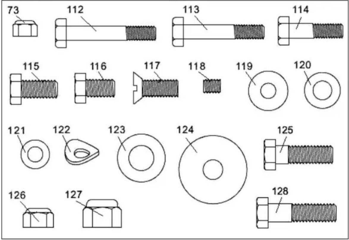
Fig.5
(73) Self locking M-8.
(112) Bolts M-8x50.
(113) Bolts M-8x45.
(114) Bolts M-8x38.
(115) Bolts M-8x20.
(116) Bolts M-8x16.
(117) Slot head bolt M-10x20.
(118) Countersunk screw 5/16"x3/8".
(119) Flat washers M-8/20.
(120) Flat washers M-8.
(121) Flat washers M-10.
(122) Washers M-10.
(123) Flat washers M-12.
(124) Flat washers 38x11XT4.
(126) Self locking M-10.
(127) Self locking M-12.
(128) Bolts M-10x34.
1.- ASSEMBLY.-
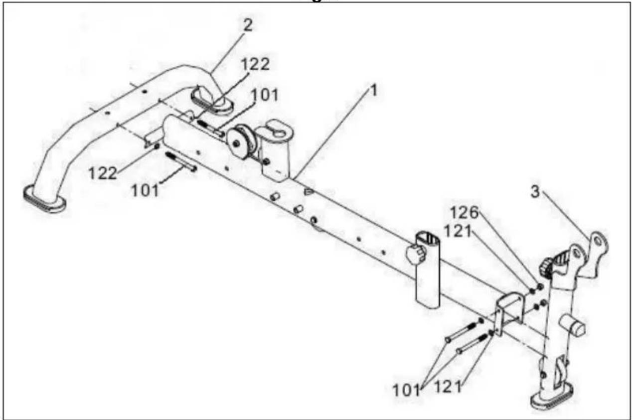
Place the main support (1) horizontally, as shown in Fig.6.
2.- Place the rear support (2) on the main support (1), as shown in Fig.6, Place the screws (101) along with the curved washers (122).
3.- Position the front support (3), as shown in Fig.6, fit screws (101) along with the curved washers (121) and nuts (126) and tighten securely.
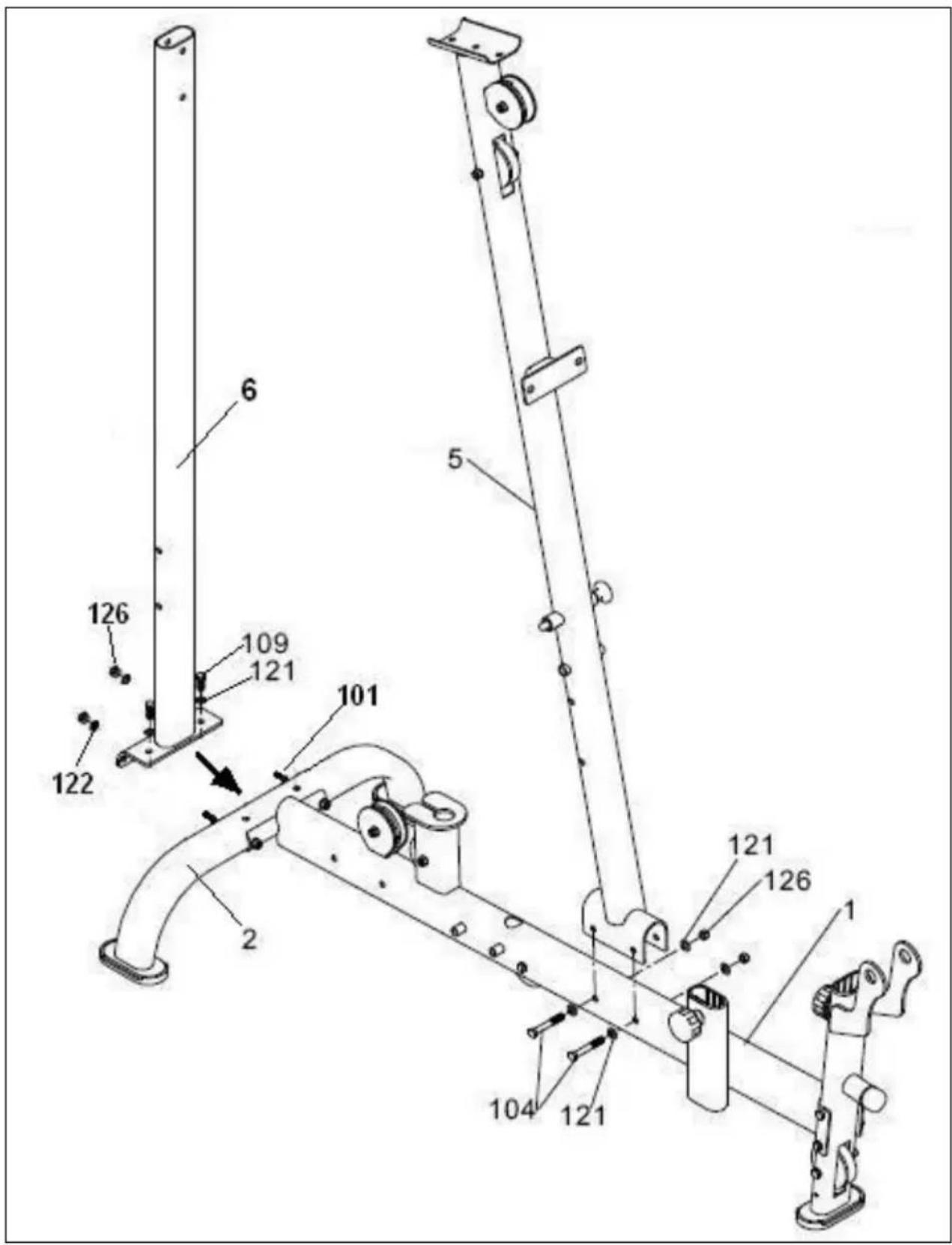
4.- Fit the vertical post (6) onto the rear support (2), as shown in Fig.7.
Fit screws (109) along with the washers (121) and tighten securely.
Fit the washers (122) and nuts (126) and tighten securely Fig.7.
Make sure that the vertical post (6) is vertical, Fig.7.
5.- Fit the main body (5) onto the main support (1), as shown in Fig.7.
Fit screws (104) along with the washers (121) and nuts (126) and tighten securely.
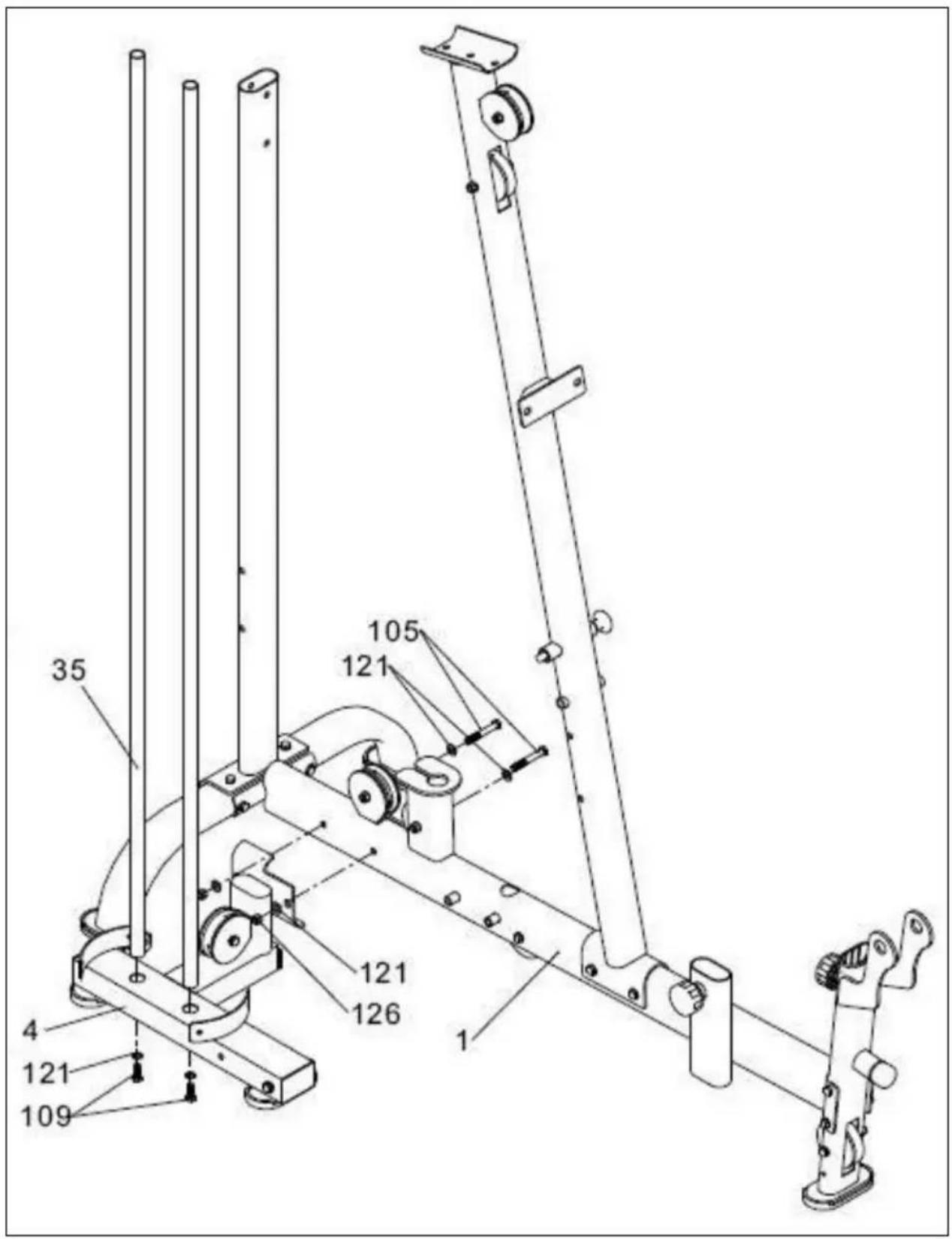
6.- FITTING THE WEIGHTS.-
Fit the weight guide bars (35) into the bottom casing bracket (4), Fig.8, fit screws (109) along with the washers (121) and tighten securely. Next, place it on the main support (1), Fig.8, fit screws (105) along with the washers (121) and nuts (126) and tighten securely.
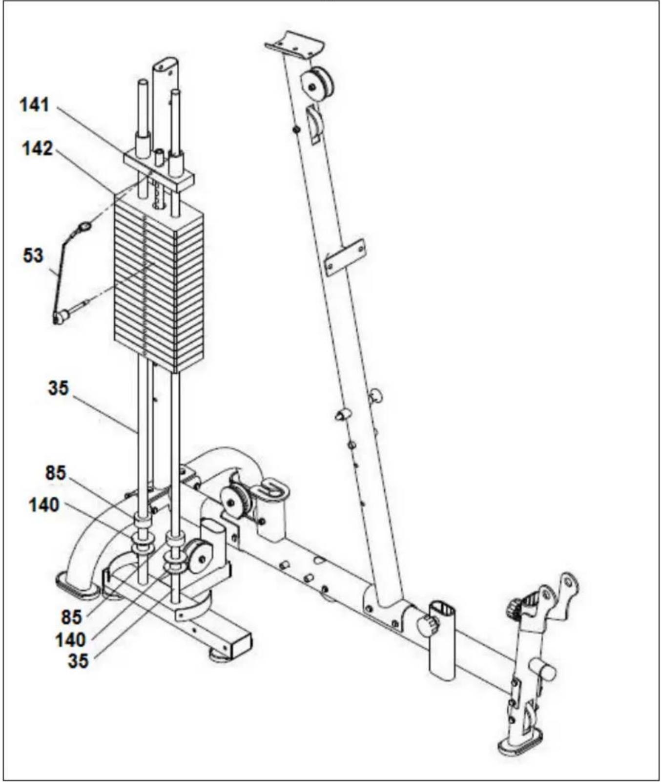
7.- Now fit the bottom washer for the weights (140) and the bottom stop for the weights (85), Fig.9.
Place the weights (142) onto the guide bars as shown in Fig.9.
Fit them in alphabetical order with the letters facing away from the machine, starting with the letter "L".
8.- Now take the weight selector post (141), Fig.9, and insert it onto the last weight, fit the selector ring (53) onto the central boss on the weight selector post, as shown in Fig.10.
9.- ASSEMBLING THE TOP SECTION.-
Place the top body (7), Fig.10, onto the main body (5), inserting it onto the vertical body (6), Fig.10.
Attach the vertical body (6), Fig.10, using screws (107) along with the washers (121) and nuts (126) and tighten securely.
Now fit screws (106) for attaching the top body (7) with the main body (5) along with the washers (121) and nuts (126) and tighten securely.
10.- Next, fit the top casing bracket (10), first inserting it on the weight guide bars (35) and then brining it up to the top support (7), Fig.10.
Fit screws (109) along with the washers (121) and hand tighten. Insert screws (101), along with the curved washers (122) and nuts (126), and tighten securely, Fig.10. Manually check that the weight selector post (141) travels smoothly along the full length of the weight guide bars and then tighten screws (109) securely.
11.- Now screw the end of the top cable (66) into the central boss on the weight selector post (141), Fig.10, and tighten the lock nut.
12.- FITTING THE GLUTEAL ACCESSORY.-
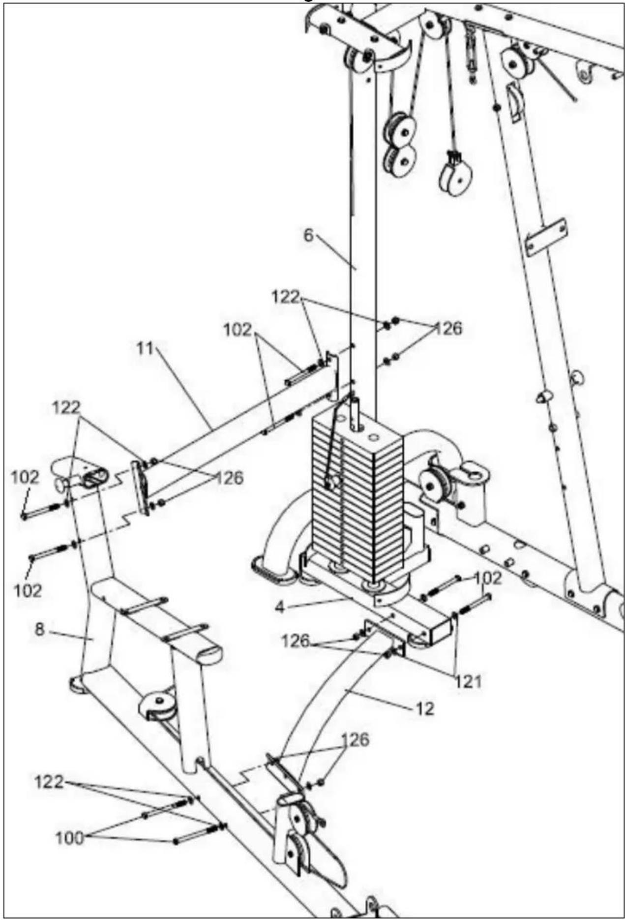
Position the rear connection bracket (11) and attach it to the vertical tube (6), Fig.11, and the gluteal support tube (8), fit screws (102) along with the curved washers (122) and nuts (126).
13.- Now position the bottom connection bracket (12), Fig.11, on the bottom casing bracket (4) and fit screws (102) along with the washers (121) and nuts (126). Then attach the other end onto the gluteal support tube (8), Fig.11, fit screws (100) along with the curved washers (122) and nuts (126) and tighten, Fig.11.
NOTE: Once this stage of the assembly has been completed, all of the bolts fitted previously should be retightened securely.
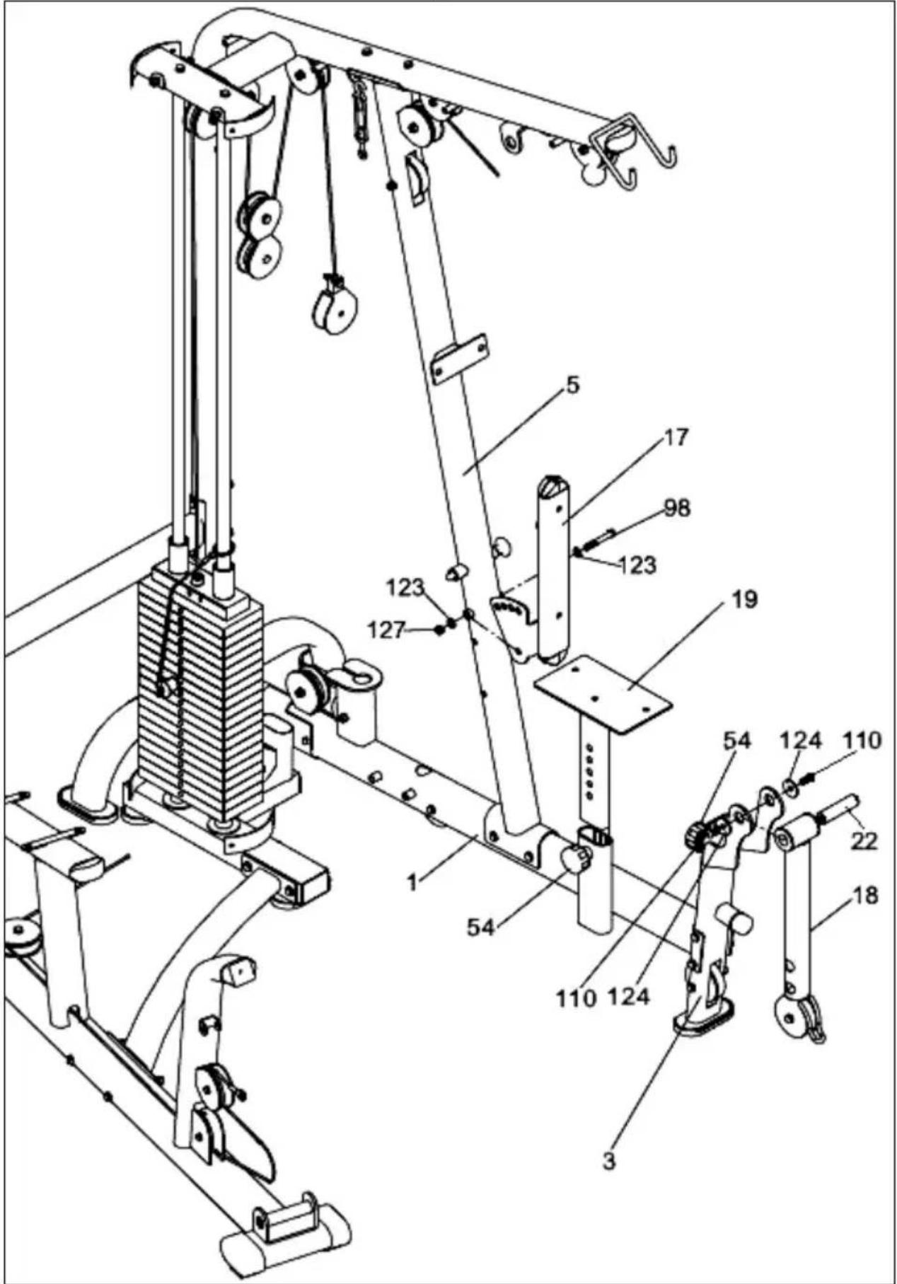
14.- FITTING THE SEAT & BACKREST STRUCTURE.-
Loosen off knob (54) by turning it anticlockwise a few turns, Fig.12, and pull the knob outward. Insert the seat support (19) onto the post sticking out of the main support (1), Fig.12. Line up one of the height setting holes, Fig.12, on the seat support and release the knob then tighten the knob (54) by turning it clockwise.
15.- Position the backrest (17) on the main body (5), Fig.12. Insert screw (98), along with washers (123) and locknut (127), and tighten securely.
Take the leg support (18), fit the spacer on the inside of the bushing for the leg support, Fig.12.
Fit it into the holes on the front support (3) and by lining up the holes insert screws (110) along with the washers (124) and secure using two spanners.
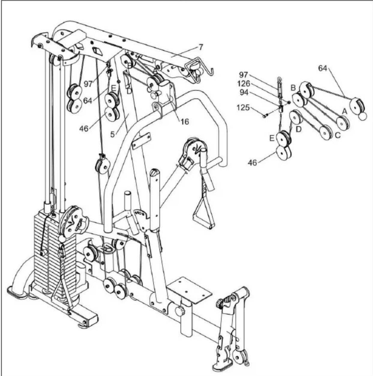
Fit the butterfly arm support (9) onto the main body (5), Fig.13. Insert screws (101), along with washers (121) and nuts (126), and tighten securely.
18.- Take cable (68) and mount the pulley (C) on the bracket (47) for the top cable (66), as shown in Fig.13, using screw (108) along with the washer (121) and piece (139). Fit nut (126) and tigthen.
Then mount pulleys (B and D) onto the main support (1) Fig.13, fit the cable exit covers and attach using screws (99), along with the washers (121) and tighten using nuts (126).
Do the same as described above for pulleys (A and E), Fig.13.
Fit the bars (133) to the piece (139) and tighten as shown in the figure.
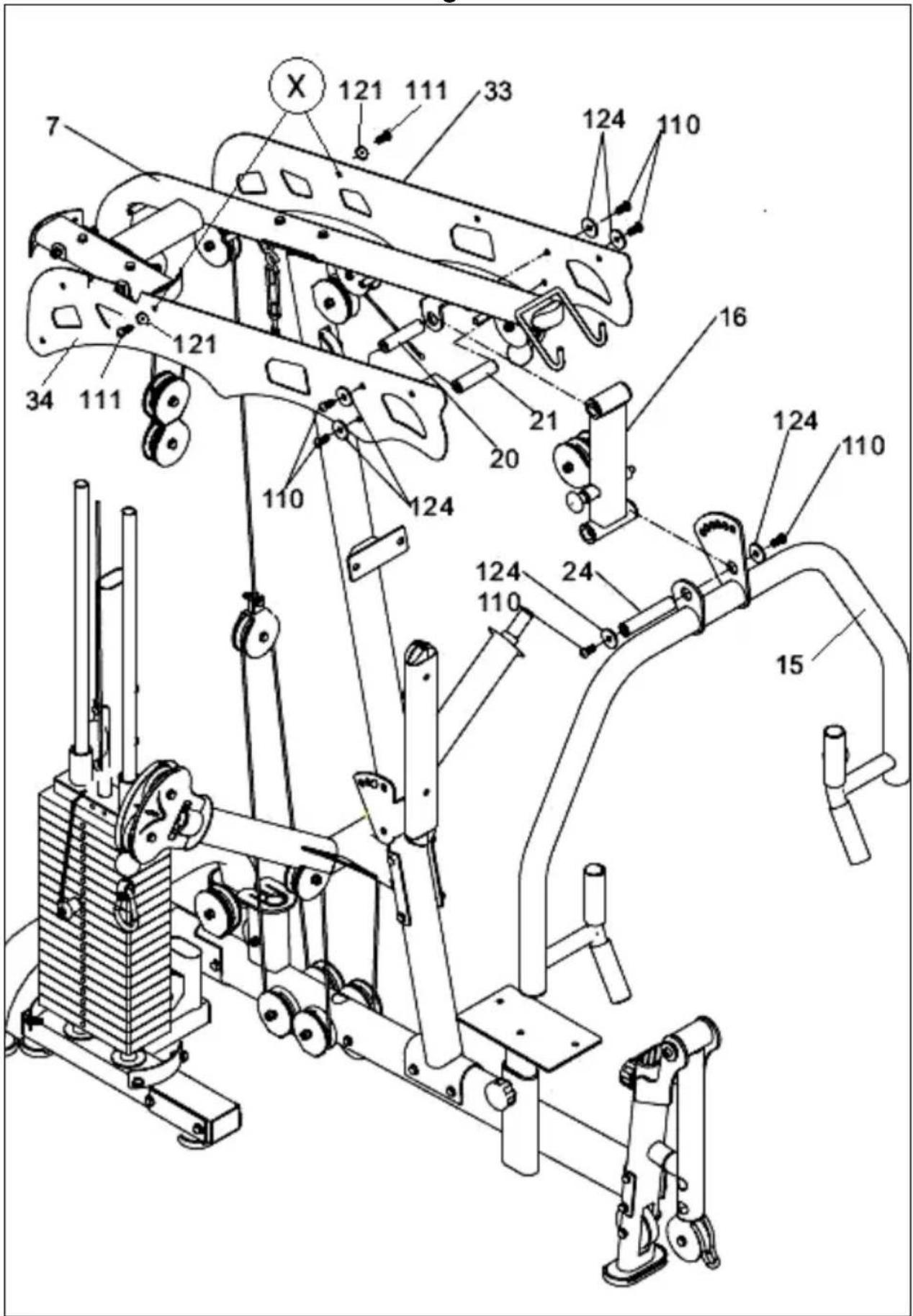
19.- FITTING THE CHEST & TRICEP SUPPORT.-
First, position the top right side panel (34) on the main body (7), Fig.14. Without tightening, insert screw (111) along with washer (121) into hole (X), as shown in Fig.14.
Then position the top left side panel (33) on the main body (7), Fig. 14. Without tightening, insert screw (111) along with washer (121) into hole (X), as shown in Fig.14.
20.- Fit spacer (20) onto the arm support (16), Fig.14, and position it on the "U" for the main body (7).
Lift the top right side panel and secure it using screw (110) along with washer (124), Fig.14.
Now do the same for the left side panel. Position the stop for the arm support (21) on the top side panels and tighthen securely.
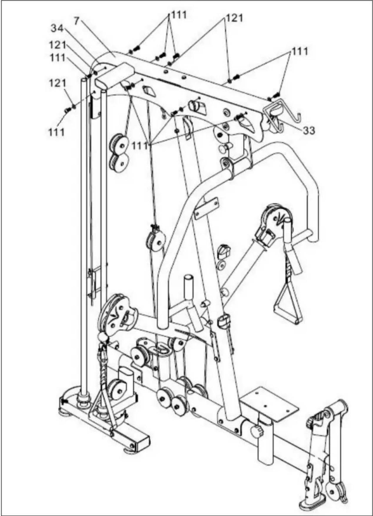
21.- Fit spacer (24) onto the bottom section of the arm support (16), Fig.14, and secure it using screws (110) along with the washers (124), Fig.14. Fiinish off by securing the side panels using (111) with their washers (121), Fig.15.
NOTE: Once this stage of the assembly has been completed, all of the bolts fitted previously should be retightened securely.
22.- Next thread cable (64), which is already mounted on pulleys (F) and (G) of the top body (7), Fig.16, through pulleys (H); (I); (J); (K) and (L). Take the chain hook (94) and join the end of cable (64), which you have just threaded through, with the cable tensioner (97), Fig.16.
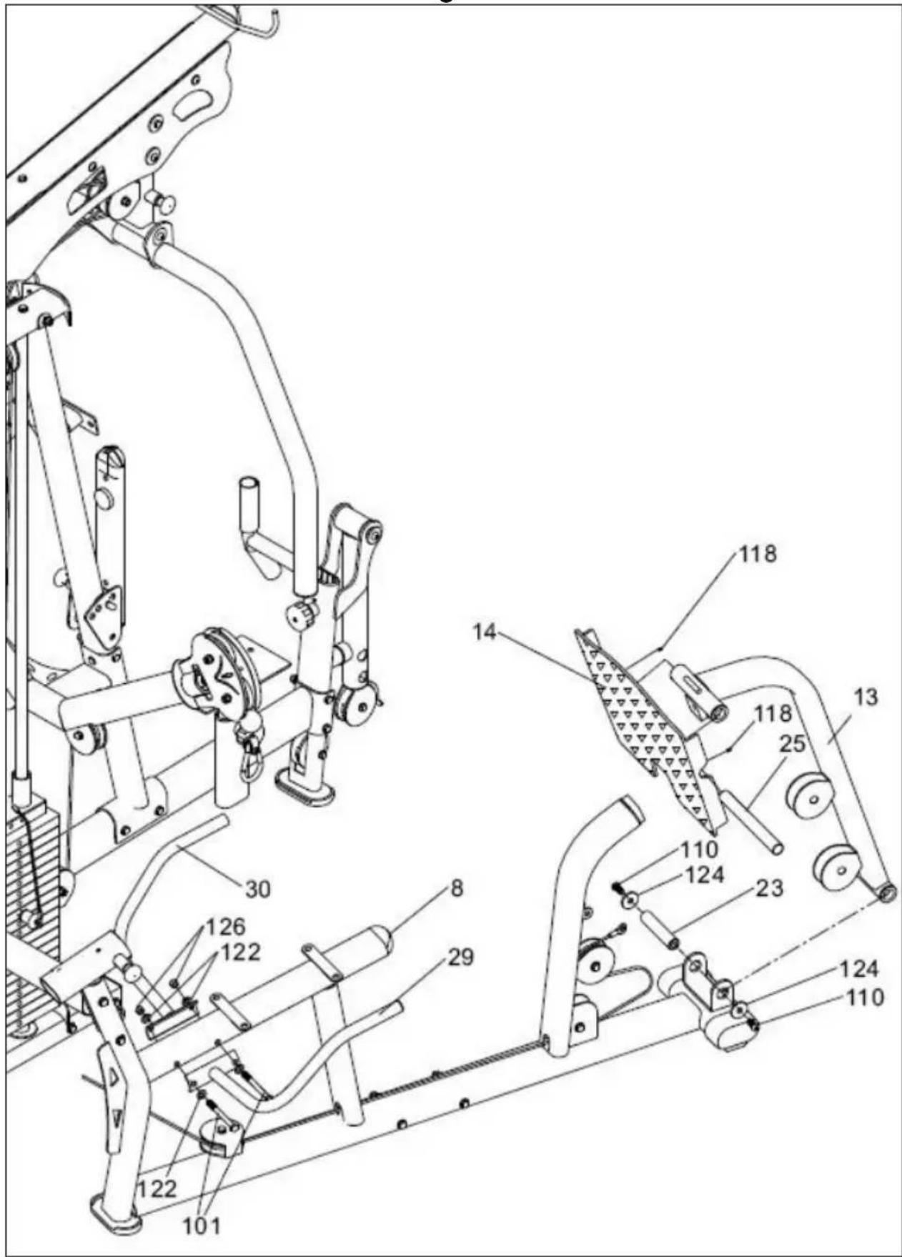
Position the gluteal push bar support (13) on the "U" for the gluteal support, as shown in Fig.19.
Align the holes on the "U" with the push bar support (13), fit the spacer (23) and tighten securely using screws (110) along with the washers (124).
24.- Take push bar (14) and insert it through the gluteal support in the direction of the arrow, insert the shaft (25) leaving it centred and fit screw (118), tighten securely.
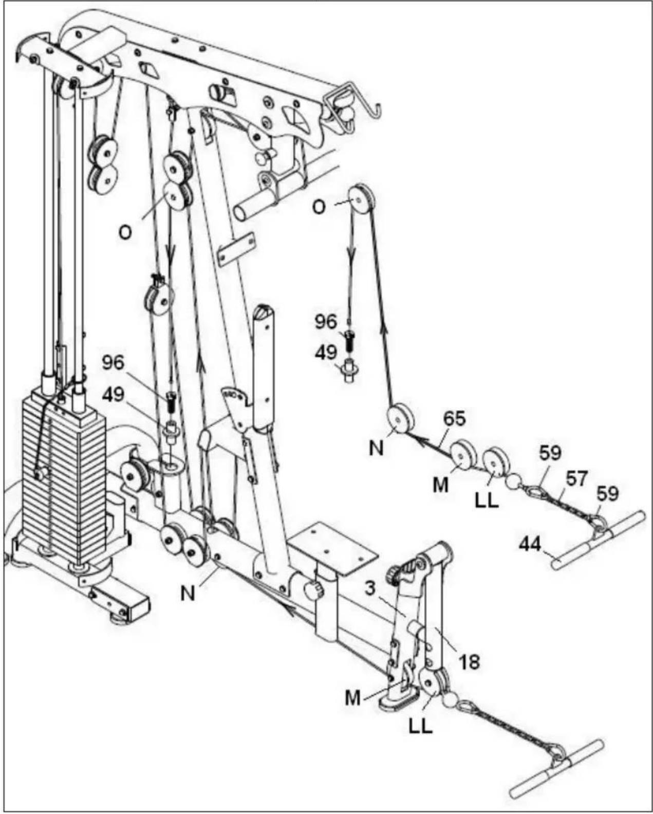
Take the end of the foot pull-up cable (65) and by following the arrows marked on the cable in Fig.18, pass it through the first pulley (LL), as shown in Fig.18. Next, pass the same tip through the lower pulley (M) and (N), Fig.18. Continue passing the tip of the cable (64) through the fourth pulley (O) Fig.18. Attach the end of the cable to the cable tensioning nut (49), Fig.18.
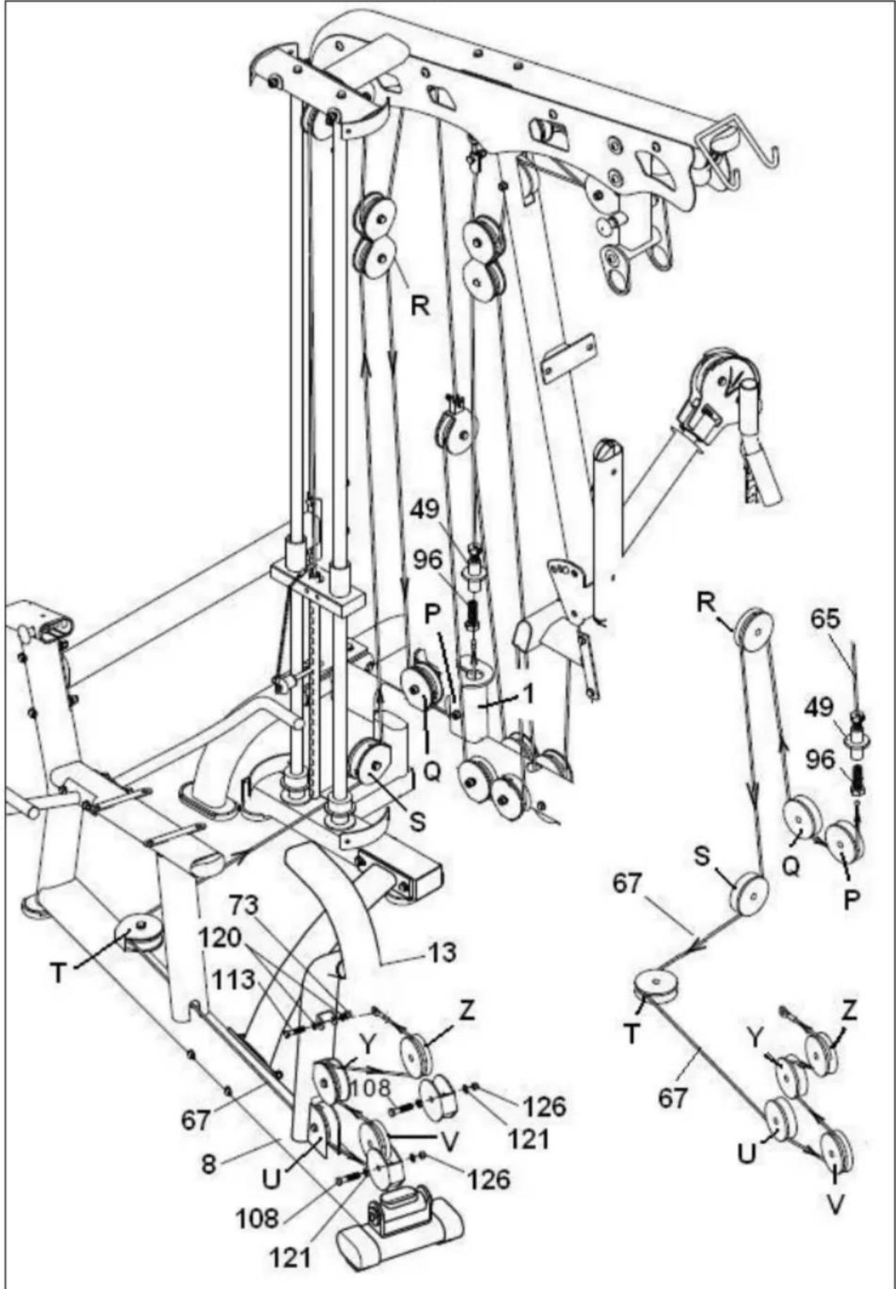
Attach the end of the cable to the cable tensioning nut (49), Fig.19. Take the other end of the cable (67) and by following the arrows marked on the cable in Fig.19, pass it through the first pulley (P), as shown in Fig.19. Next, pass the same tip through the pulley (Q) and (R), Fig.18. Continue passing the tip of the cable (64) through pulley (S), (T), (U); (V); (Y) and (Z) Fig.19.
27.- Attach the end of the cable to the "U" on the tube (8) for the gluteal support using screw (113) along with washers (120) and nut (73), Fig.19.
Note: After a while you may notice that the steel cable slackens a little due to the cable settling into position. To remedy this, just tighten the steel cable (65) and (67) on the tensioning nut (49).
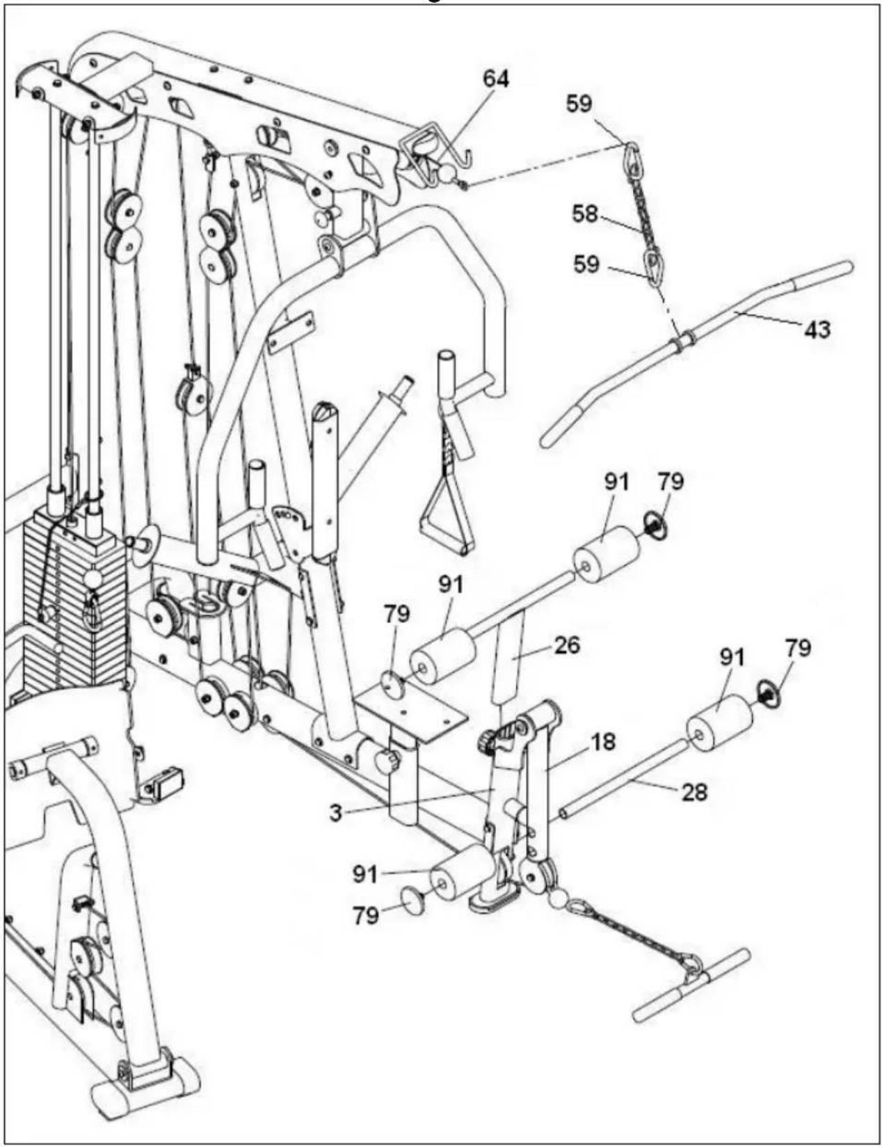
First take the top leg tube (26) and fit and insert it into the leg support (3), Fig.20, fit the foam covers (91) onto the rounded ends of the leg support, Fig.20.
Now do the same for the bottom foam covers (91) for the leg support (18).
Finally, fit the caps (79) onto the ends of the foam covers (91), Fig.20.
29.- Attach the end of cable (64) to the carabiner (59) and the chain (58), Fig.20.
Take the seat (40) and position it on the seat support (19), Fig.21. Attach using screws (115) and washers (119). Take the backrest (38) and position it on the abdominal support (17), as shown in Fig.21.
Now use screws (112) and washers (119) to secure the backrest, Fig.21.
Take the headrest (42) and position it on the main body (5), as shown in Fig.21.
Now use screws (115) and washers (119) to secure the backrest, Fig.21.
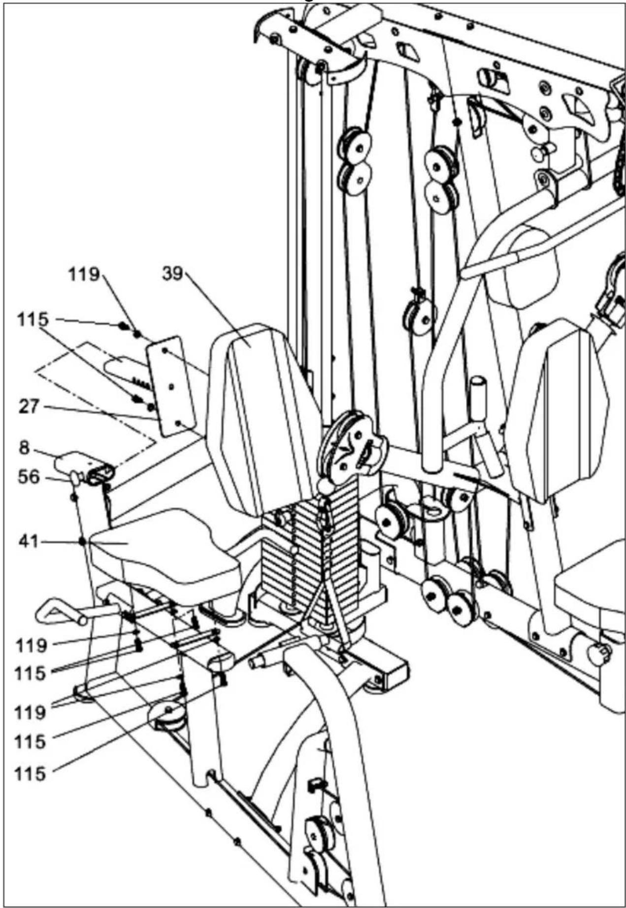
Pulling knob (56) outward, Fig.22, insert the back support (27) into the boss on the gluteal support (8), Fig.22.
Position it at one of the backrest distance holes and release the knob (56).
Take the backrest (39) and position it on the backrest support (27), as shown in Fig.22.
Now use screws (115) and washers (119) to secure the backrest, Fig.22.
Take the seat (41) and position it on the seat support (8), Fig.22.
Fit screws (115) with their washers (119) and tighten securely.
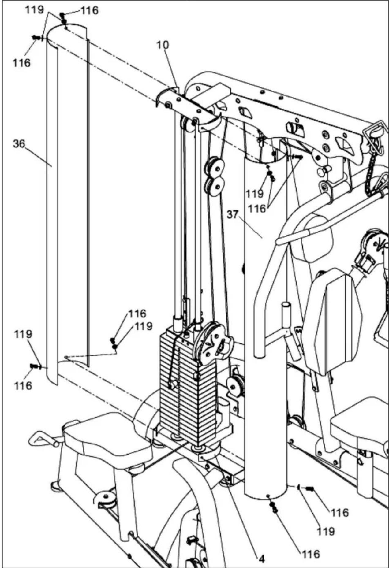
32.- CASING ASSEMBLY.-
Fit the front left and front right safety covers (36 and 37) onto the top casing bracket (10), Fig.23, hand tightening screws (116) along with the washers (119) on the top section, Fig.23.
Also fit covers on the bottom bracket (4) Fig.23, using screws (116) with washers (119), on the bottom section, Fig.23.
Do not hesitate to get touch with the Technical Assistance Service if you have any queries by phoning customer services (see last page in manual)
BH RESERVES THE RIGHT TO MODIFY THE SPECIFICATIONS OF ITS PRODUCTS WITHOUT PRIOR NOTICE.
Français
MONTAGE.-
(18) Support jambes.
(19) Support siège.
Fig.2
(68) Cabo tiro Butterfly.
text_image
Technical schematic diagram with numbered components and labeled parts, likely from an engineering or mechanical assembly.To order replacement parts: State the part code and Quantity
e-mail: info@bhfitness.pt
BH SERVICE PORTUGAL
Tel.: +351 234 729 510
Fax: +351 234 729 519
e-mail: info@bhfitness.pt
BH GERMANY GmbH
Altendorfer Str. 526
45355 Essen
Tel: +49 201 450910-0
e-mail:
info@bhgermany.com
Toll free: +1 866 325 2339
service.uk@bhfitness.com
BH FITNESS ASIA
BH Asia Ltd.
No.80, Jhongshan Rd.,
Daya Dist.,
Taichung City 42841,
Taiwan. R.O.C.
Tel.: +886 4 25609200
Fax: +886 4 25609280
Block A, NO.68, Branch Lane
455, Lane 822,
Zhen Nan RD., Li Zi Yuan,
Putuo, Shanghai 200331, P.R.C.
Tel: +86-021-5284 6694
Fax:+86-021-5284 6814
e-mail: info@i-bh.cn
BH FITNESS FRANCE
SAV FRANCE
Tel : +33 0810 000 301
Fax : +33 0810 000 290
savfrance@bhfitness.com
BH SE RESERVA EL DERECHO A MODIFICAR LAS ESPECIFICACIONES DE SUS PRODUCTOS SIN PREVIO AVISO.
SPECIFICATIONS MAY BE CHANGED WITHOUT PRIOR NOTICE DUE TO OUR PROGRAMME OF CONTINUOUS PRODUCT DEVELOPMENT.
BH SE RÉSERVE LE DROIT DE MODIFIER LES SPECIFICATIONS DE SES PRODUITS SANS PRÉAVIS.