IT 101 - Measuring equipment BENNING - Free user manual and instructions
Find the device manual for free IT 101 BENNING in PDF.

| Product Type | Megohmmeter and ohmmeter for insulation resistance, low impedance, resistance, AC/DC voltage, PI/DAR measurement |
| Brand | BENNING |
| Model | IT 101 |
| Dimensions (without holster) | 200 x 85 x 40 mm |
| Dimensions (with holster) | 207 x 95 x 52 mm |
| Weight (without holster) | 470 g |
| Weight (with holster) | 630 g |
| Power supply | 4 AA 1.5 V batteries (IEC LR6) |
| Battery life | Approximately 2600 low impedance measurements or 1100 insulation measurements at 1000 V |
| Display | 3½-digit LCD, 15 mm character height, 49-segment bargraph, automatic backlight |
| Main functions | Insulation resistance measurement (50 V/100 V/250 V/500 V/1000 V), low impedance measurement, resistance measurement, AC/DC voltage measurement, PI/DAR measurement, COMPARE function, low-pass filter (LPF), zero compensation, LOCK function, internal memory 100 locations |
| Overvoltage category | 600 V category IV |
| Protection degree | IP 40 |
| Standards | DIN VDE 0411, EN 61010, EN 61557 |
| Maintenance | Clean with dry cloth; replace batteries when symbol appears; replace fuse (315 mA / 1000 V / FF) if necessary |
| Safety | Double insulation (class II), auto power off after 20 min (30 min in lock mode), hazardous voltage warning above 30 V AC/DC |
| Replacement parts | Fuse FF 315 mA, 1000 V, 10 kA, D=6.3 mm, L=32 mm (ref. 757213); AA batteries |
| Supplied accessories | 2 safety test leads, 2 alligator clips, switchable test probe with TEST button, rubber holster, magnetic hanging device, protective case, batteries, fuse |
Frequently Asked Questions - IT 101 BENNING
User questions about IT 101 BENNING
0 question about this device. Answer the ones you know or ask your own.
Ask a new question about this device
Download the instructions for your Measuring equipment in PDF format for free! Find your manual IT 101 - BENNING and take your electronic device back in hand. On this page are published all the documents necessary for the use of your device. IT 101 by BENNING.
USER MANUAL IT 101 BENNING
Fig. 3: Voltage measurement with AUTO SENSE function
Fig. 4: Resistance and low-resistance measurement
Fig. 5: Insulating resistance measurement (symbolic)
Fig. 6: Measuring the polarization index (PI) / dielectric absorption rate (DAR)
Fig. 8: Measuring results after DAR measurement
natural_image
Technical line drawing of a car interior showing internal components and battery pack (no text or labels)Bild 13: Batterie- und Sicherungswechsel Fig. 13: Battery and fuse replacement Fig. 13: Remplacement des piles et du fusible figura 13: Смяна на батериите и предпазителя Obr. 13: Výměna baterie a pojistky Eikóva 13: Аллаýň μπαταριών και ηλεκτρικής ασφάλειας 13. ábra: Telep és biztosító csere III. 13: Sostituzione di batterie e fusibile Fig. 13: Batterij en zekering vervangen Rysunek 13: Wymiana baterii i bezpiecznika Imaginea 13: Schimbarea bateriei și al siguranțelor Bild 13: Batteri-/säkringsbyte

natural_image
Technical line drawing of two mechanical components with no visible text or symbolsBild 14: Aufwicklung der Sicherheitsmessleitung Fig. 14: Winding up the safety measuring leads Fig. 14: Enroulement du câble de mesure de sécurité figura 14: Закрепване на сондите Obr. 14: Navinuti bezpečnostních měřících kabelů Eikóva 14: Перитúlišn tou μετρητικού αγωγού ασφαλείας 14. ábra: A mérővezetékek felcsavarása III. 14: Avvolgimento dei cavetti di sicurezza Fig. 14: Wikkelen van de veilighheidsmeetsnoeren Rysunek 14: Zwijanie bezpiecznych przewodów pomiarowych Imaginea 14: Înfăşurarea firelor de măsurare pe ram din cauciuc Bild 14: Fastlindning av säkerhetsmätkablarna
natural_image
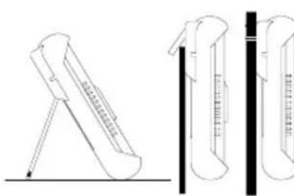
Technical line drawings of laboratory test tubes with stand and vertical scale (no text or symbols)Bild 15: Aufstellung des BENNING IT 101 Fig. 15: Erecting the BENNING IT 101 Fig. 15: Installation du BENNING IT 101 figura 15: Повдигане на BENNING IT 101 Obr. 15: Postavení přístroje BENNING IT 101 Ейкова 15: Тотоётног tou BENNING IT 101 15. ábra: A BENNING IT 101 felállitása III. 15: Posizionamento del BENNING IT 101 Fig. 15: Opstelling van de BENNING IT 101 Rysunek 15: Zamontowanie przyządu BENNING IT 101 Imaginea 15: Pozitionarea pe verticală a aparatului BENNING IT 101 Bild 15: Uppställning av BENNING IT 101
Polarisation Index (PI) = R10-Min/ R1-Min
Operating instructions BENNING IT 101
Insulation and resistance measuring instrument for:
- Insulating resistance measurements
- Low-resistance measurements
- Resistance measurements
- Direct voltage measurements
- Alternating voltage measurements
- Measuring/ calculating the polarization index (PI)
- Measuring/ calculating the dielectric absorption rate (DAR)
Contents
- User notes
- Safety note
- Scope of delivery
- Description of appliance tester
- General information
- Ambient conditions
- Electrical specifications
- Measuring with the BENNING IT 101
- Maintenance
- Application of rubber protection frame
- Environmental note
1. User notes
These operating instructions are intended for
- qualified electricians, competent persons and
- electrotechnically trained persons
The BENNING IT 101 is intended for making measurements in dry environment. It must not be used in power circuits with a nominal voltage higher than 600 V DC/ AC (more details in Section 6. "Ambient conditions").
The following symbols are used in these operating instructions and on the BENNING IT 101:

Attention! Magnets might affect the correct functioning of cardiac pacemakers and implanted defibrillators. As a user of such medical devices, keep a sufficient distance to the magnet.

Warning of electrical danger!
Indicates instructions which must be followed to avoid danger to persons.

Important, comply with the documentation!
This symbol indicates that the stipulations in the operating instructions must be followed in order to avoid danger.

This symbol on the BENNING IT 101 means that the BENNING IT 101 is totally insulated (protection class II).
This warning symbol indicates that the BENNING IT 101 must not be used in distribution systems with voltages higher than 600 V.

This symbol on the BENNING IT 101 means that the BENNING IT 101 complies with the EU directives.

This symbol appears on the display to indicate a discharged battery.

This symbol on the BENNING IT 101 indicates the built-in fuses

(DC) direct current or (AC) alternating current

Earth (voltage to ground)

At the end of product life, dispose of the unserviceable device via appropriate collecting facilities provided in your community.
2. Safety note
The instrument is built and tested in accordance with
DIN VDE 0411 part 1/ EN 61010 part 1
DIN VDE 0411 part 2-033/EN 61010-2-033
DIN VDE 0411 part 031/EN 61010-031
DIN VDE 0413 part 1, 2 and 4/ EN 61557 part 1, 2 and 4
and has left the factory in perfectly safe technical condition.
To maintain this condition and to ensure safe operation of the appliance tester, the user must observe the notes and warnings given in these instructions at all times. Improper handling and non-observance of the warnings might involve severe injuries or danger to life.

Attention! Magnets might affect the correct functioning of cardiac pacemakers and implanted defibrillators. As a user of such medical devices, keep a sufficient distance to the magnet.

The instrument may be used only in electrical circuits of over voltage category IV with a maximum voltage of 600 V between the conductor and ground.
Only use suitable measuring leads for this. With measurements within measurement category III or measurement category IV, the projecting conductive part of a contact tip of the measuring leads must not be longer than 4 mm.
Prior to carrying out measurements within measurement category III and measurement category IV, the push-on caps provided with the set and marked with CAT III and CAT IV must be pushed onto the contact tips. The purpose of this measure is user protection.
Remember that work on electrical components of all kinds is dangerous. Even low-voltages of 30 V AC and 60 V DC may be dangerous to human life. As from an input voltage of 30 V AC/ DC the warning symbol ⚠️ R appears on the display of the BENNING IT 101, as a warning that a dangerous voltage is connected. In addition, the red high-voltage indicator ⚠️ ⑨ lights up.

Before starting the appliance tester, always check it as well as all measuring leads and wires for signs of damage.

Important! During the insulating resistance measurement, dangerous levels of voltage may occur in the BENNING IT 101.
Should it appear that safe operation of the appliance tester is no longer possible, it should be shut down immediately and secured to prevent that it is switched on accidentally.
It must be assumed that safe operation is no longer possible
- if the instrument or the measuring leads show visible signs of damage, or
- if the appliance tester no longer works, or
- after long periods of storage under unfavourable conditions, or
- after being subject to rough transportation, or
- if the device is exposed to moisture.

In order to avoid danger,
- do not touch the bare probe tips of the measuring leads
- when measuring voltage disconnect the switchable probe tip from the BENNING IT 101 at first
- plug the measuring leads into the correspondingly designated measuring sockets on the BENNING IT 101 see Fig. 1: Front tester panel
- when disconnecting the measuring circuit, always disconnect the voltage carrying measuring cable (phase) first and then disconnect the neutral measuring lead
- do not operate the BENNING IT 101 in the vicinity of explosive gases or dust.

Maintenance:
Do not open the tester, because it contains no components which can be repaired by the user. Repair and service must be carried out by qualified personnel only!

Cleaning:
Regularly wipe the housing by means of a dry cloth and cleaning agent. Do not use any polishing agents or solvents!
3. Scope of delivery
The scope of delivery for the BENNING IT 101 comprises:
3.1 one BENNING IT 101
3.2 two safety measuring leads, red/ black (L = 1.2 m)
3.3 two safety alligator clip, red/ black, 4 mm plug-in system
3.4 one switchable probe tip with integrated TEST key (part no. 044115)
3.5 one rubber protection frame
3.6 one magnetic holder with adapter and strap (part no. 044120)
3.7 one compact protective pouch
3.8 four mignon batteries 1.5 V/ type AA according to IEC LR6 and one fuse (fitted in unit as initial equipment),
3.9 one operating manual
Parts subject to wear:
- The BENNING IT 101 contains a fuse as protection against overload: One fuse, nominal current rating 315 mA (1000 V), 10 kA, FF, D = 6.3 mm, L = 32 mm (part no. 757213)
- The BENNING IT 101 is powered by four mignon batteries 1.5 V/ type AA according to IEC LR6.
4. Description of the appliance tester
See figure 1: Front side of the instrument
See figure 2: Digital display
The display and operator control elements specified in Fig. 1 and 2 are designated as follows:
① Sensor, of the automatic background lighting
② Digital display
A AUTO SENSE, for automatic detection of DC and AC voltage,
B Digital display, for the measured value and analogue bar graph display,
© TEST, appears when the measuring function for insulating resistance and low resistance is activated,
D LOCK (latching), permits continuous measurement of insulating resistance and low resistance,
E APO, Auto Power Off is activated,
F LPF, is indicated with the low-pass filter being activated,
G AC/ DC, is indicated when a DC or AC voltage is measured,
H →0+, is indicated in case of compensation (null balance) of the measuring leads,
① Range indication,
① COMPARE, is indicated in case of the comparative function of insulating resistance measurement,
K DAR, is indicated if the measurement of the dielectric absorption rate is activated,
PI, is indicated if the measurement of the polarization index is activated,
Testing voltage indication, is indicated when the insulating resistance is measured,
N Clock, measuring time of the PI / DAR measurement,
① Battery condition indicator „-+“, appears when the battery is discharged,
P Overflow,
① Polarity indication,
R (high-voltage indicator), is indicated if a dangerous voltage is applied,
S MEM, is indicated when an internal memory of measured values is activated,
③ Key (blue), change-over key for the secondary function,
4 COMP key, activates the comparative function for insulating resistance measurement,
⑤ STORE / RECALL key, storage and call of measured values,
6 LOCK (latching)/ PI/DAR key, permits continuous measurement of insulating resistance and low-resistance as well as activates the measurement of the dielectric absorption rate and of the polarization index,
⑦ Green LED (PASS), lights up, if the measured value exceeds the comparative value (resistance value) in the COMP mode,
8 TEST key, activates the measurement of the insulating resistance and of the low-impedance resistance,
9 Red LED (high-voltage control indicator), lights up if a dangerous
voltage is applied,
10 Rotary switch, for selecting the measuring function,
⑪ Ω socket, for resistance and low-resistance measurement,
⑫ Jack (positive), for measuring voltages and insulation, polarization index (PI), dielectric absorption rate (DAR),
13 COM jack, common jack for measurements of voltage, resistance, low-impedance, insulation, polarization index (PI) and dielectric absorption rate (DAR)
14 Rubber protective frame.
5. General information
The BENNING IT 101 is intended for measuring the insulating resistance.
The BENNING IT 101 supports electric safety tests according to DIN VDE 0100, IEC 60364, VDE 0701-0702, BGV A3, ÖVE/ ÖNORM E8701 and NEN 3140.
Preset limiting values make it easier to evaluate the test.
5.1 General information concerning the insulation measuring instrument
5.1.1 The digital display B for the measurement readings B is a 3½-digit liquid crystal display with decimal point. The height of the displayed digits is 15 mm. The largest numerical value which can be displayed is 4000.
5.1.2 The bar graph display consists of 49 segments and depicts resistance readings on a logarithmic scale.
5.1.3 The polarity indication ① is automatic. Only one polarity with respect to the socket marked " - " is indicated.
5.1.4 The digital display for the test voltage is a 3½ digit liquid crystal display with 7 mm high numerals. The largest value which can be displayed is 1999.
5.1.5 Range overflow of the digital display ② is indicated with the symbol >" P.
5.1.6 The BENNING IT 101 has an automatic measuring range selection function (auto ranging).
5.1.7 The BENNING IT 101 is provided with an automatic background lighting ("Auto Backlight"). The brightness sensor is located on the top side of the device ①. As soon as the ambient lighting decreases, the background lighting will switch on automatically.
5.1.8 An acoustic signal (buzzer) will sound once for each valid keystroke and twice in case of an invalid keystroke.
5.1.9 The secondary function of the rotary switch position can be selected by means of the key (blue) ③. The low-pass filter (LPF) is activated in switch position V. A compensation (null balance) of the measuring leads is possible with switch position Ω (→0)The insulating resistance or leakage current is indicated with switch positions 50 V/ 100 V/ 250 V/ 500 V and 1000 V.
5.1.10 The COMP key ④ activates the comparative function for insulating resistance measurement.
5.1.11 The STORE/ RECALL key ⑤ is intended for storage and call of measured values.
5.1.12 The key LOCK (latching) ⑥ permits continuous measurements of insulating resistance and low-resistance without having to press the TEST key ⑧ repeatedly or to hold it. To switch over to continuous measurements, press the LOCK key and then the TEST key. The “LOCK” symbol D appears on the display ②. When measuring the insulating resistance, pressing the TEST key continually applies the test voltage to the measuring point. When measuring low-resistance, pressing the key TEST continually applies the test current to the measuring point. The locked state can be terminated by pressing the LOCK key or the TEST key.
4
In locked mode (key) the BENNING IT 101 recognizes no external voltage at the input of the instrument. Make sure that the measuring point is free of voltage before activating the locked mode, otherwise the fuse might blow.
The LOCK key activates the measurement of the dielectric absorption rate (DAR) and of the polarization index (PI) .
5.1.13 The green LED ⑦ (PASS indicator) lights for the comparative function (COMP key ④), if the measured value exceeds the comparative value (resistance value).
5.1.14. The TEST key ⑧ activates the measuring function for insulating resistance and low-resistance.
5.1.15 The red LED ⑨ (△ high-voltage control indicator) lights up, if a dangerous voltage is applied. The warning symbol △ R is indicated on the display ② of the BENNING IT 101.
5.1.16 The BENNING IT 101 is switched on and off with the rotary switch ⑩.
The off setting is "OFF".
5.1.17 The BENNING IT 101 switches itself off automatically after approx. 20 minutes. In locked mode ("LOCK") D (continuous measurements) automatic switch off takes place after 30 minutes. The instrument switches itself on again automatically when a key is actuated, or the measuring range selector switch is turned, or a voltage higher than 30 V AC/ DC is connected to the input of the instrument.
5.1.18 Temperature coefficient of the measured value: 0.15 x (stated measuring precision)/°C < 18 °C or >28 °C, related to the value for the reference temperature of 23°C.
5.1.19 The BENNING IT 101 is powered by four 1.5 V mignon batteries (IEC LR6/ type AA).

As soon as the battery symbol ① is indicated, the batteries must be replaced by new ones immediately in order to prevent danger for persons due to incorrect measurements.
5.1.20 With new batteries the BENNING IT 101 can make approx.:
- 2600 low-resistance measurements (according to EN 61557-4) [1 Ω, for a measuring duration of 5 sec.] or - 1100 insulating resistance measurements (1000 V) (according to EN 61557-2) [1 MΩ, for 1000 V and a measuring duration of 5 sec.]
5.1.21 Appliance dimensions:
(L x B x H) = 200 x 85 x 40 mm without rubber protection frame
(L x B x H) = 207 x 95 x 52 mm with rubber protection frame
Appliance weight:
470 g without rubber protection frame
630 g with rubber protection frame
5.1.22 The safety measuring leads supplied are expressly suited for the rated voltage and the rated current of the BENNING IT 101.
5.1.23 The BENNING IT 101 is protected by a rubber protection frame ^14 against mechanical damage. The rubber protection frame allows the BENNING IT 101 to be set up or hung up during the measurements.
6. Ambient conditions
- The BENNING IT 101 is intended for making measurements in dry environment.
- Maximum barometric elevation for making measurements: 2000 m,
- Overvoltage category/ setting category: IEC 61010-1 → 600 V category IV,
- Contamination class: 2,
- Protection class: IP 40 (DIN VDE 0470-1 IEC/ EN 60529)
IP 40 means: Protection against access to dangerous parts and protection against solid impurities of a diameter > 1 mm, (4 - first index). No protection against water, (0 - second index). - EMC: EN 61326-1
- Operating temperature and relative humidity:
For operating temperatures from 0 °C to 30 °C: relative humidity less than 80 %
For operating temperatures from 31 °C to 40 °C: relative humidity less than 75 %
For operating temperatures from 41 °C to 50 °C: relative humidity less than 45 % - Storage temperature: The BENNING IT 101 can be stored at any temperature within the range of -20 °C to +60 °C (relative humidity from 0 to 80 %). The battery should be removed from the instrument for storage.
7. Electrical specifications
Note: The measuring accuracy is specified as the sum of
- a relative fraction of the measured value and
- a number of digits (counting steps of the least significant digit).
The specified measuring accuracy is valid for temperatures within the range of 18 °C to 28 °C and for a relative humidity lower than 80 %.
7.1 Voltage measuring range (Switch setting V)
| Measuring range | Resolution | Accuracy |
| 600 V DC | 0.1 V | ± (1.0 % of the measured value + 5 digits) |
| 600 V AC | 0.1 V | ± (1.5 % of the measured value + 5 digits) in frequency range 50 Hz - 60 Hz ± (2.0 % of the measured value + 5 digits) in frequency range 61 Hz - 500 Hz |
| 600 V ACwith low-pass filter (LPF) | 0.1 V | ± (1.5 % of the measured value + 5 digits) in frequency range 50 Hz - 60 Hz ± (5.0 % of the measured value + 5 digits) in frequency range 61 Hz - 400 Hz |
Optical warning in case of dangerous voltages of 30 V AC/ DC and more (△)
Min. measuring voltage: 0.6 V (AC)
Overvoltage protection: 600 V RMS or DC
Limiting frequency of the low-pass filter (LPF): 1 kHz
Input impedance: 3 MΩ / less than 100 pF
AC conversion:
The AC conversion is capacity-coupled (AC-coupled), TRUE RMS behaviour, calibrated against a sinusoidal signal. In case of non-sinusoidal curves the display value becomes less precise. Thus an additional error results for the following crest factors:
Crest factor from 1.4 to 2.0 additional errors + 1.0 %
Crest factor from 2.0 to 2.5 additional errors + 2.5 %
Crest factor from 2.5 to 3.0 additional errors + 4.0 %
7.2 Insulating resistance measuring ranges
(switch setting MΩ, 50 V/ 100 V/ 250 V/ 500 V/ 1000 V)
| Measuring range Resolution Accuracy |
| 4 MΩ 0.001 MΩ ± (1.5 % of the measured value + 5 digits) |
| 40 MΩ 0.01 MΩ ± (1.5 % of the measured value + 5 digits) |
| 400 MΩ 0.1 MΩ ± (3.0 % of the measured value + 5 digits) |
| 4000 MΩ 1 MΩ ± (3.0 % of the measured value + 5 digits) |
| 4.1 GΩ ... 20 GΩ 0.1 GΩ ± (10 % of the measured value + 3 digits) |
Minimum / maximum resistance depending on the testing voltage:
| Testing voltage | Min. resistance (at 1 mA) Max. resistance | |
| 50 V | 50 kΩ | 50 MΩ |
| 100 V | 100 kΩ | 100 MΩ |
| 250 V | 250 kΩ | 250 MΩ |
| 500 V | 500 kΩ | 500 MΩ |
| 1000 V | 1 MΩ | 20 GΩ |
Accuracy of testing voltage: - 0 %, + 20 %
Short-circuit current: 1 mA (nominal)
Automatic discharge function: discharging time < 1 sec. for C < 1 μF
Max. capacitive load: operational for loads of up to 1 μF
Detection of a connected electric circuit: if > 30 V AC/ DC, then △
7.3 Resistance measuring range (Low-resistance range) (switch setting )
| Measuring range Resolution Accuracy | ||
| 40 Ω | 0.01 Ω | ± (1.5 % of the measured value + 5 digits)* |
| 400 Ω | 0.1 Ω ± (1.5 % of the measured value + 3 digits) | |
| 4000 Ω | 1 Ω | ± (1.5 % of the measured value + 3 digits) |
| 40 kΩ | 0.01 kΩ | ± (1.5 % of the measured value + 3 digits) |
* < 1 Ω additional 3 digits
Test voltages: > 4 V and 8 V
Short-circuit current: > 200 mA
Detection of a connected electric circuit: if > 2 V AC/ DC, then △
8. Measuring with the BENNING IT 101
8.1 Preparations for measuring
Operate and store the BENNING IT 101 only at the specified storage and operating temperatures. Avoid continuous insulation.
- Check the nominal voltages and nominal current on the safety measuring leads. The nominal voltage and current ratings of the safety measuring leads included in the scope of delivery correspond to the ratings of the BENNING IT 101.
- Check the insulation of the safety measuring leads. Dispose of the safety measuring leads immediately if the insulation is damaged.
-
Check the safety measuring leads for continuity. If the conductor in the safety measuring lead is interrupted, the safety measuring leads must be dispose of immediately.
-
Before a different function is selected by means of the rotary switch 10, the safety measuring leads must be disconnected from the measuring point.
- Strong sources of interference in the vicinity of the BENNING IT 101 might lead to unstable readings and measuring errors.
8.2 Voltage measurement with AUTO SENSE function (automatic AC/ DC detection)
- Disconnect the switchable probe tip from the BENNING IT 101.
- Select the desired function (V) with the rotary switch 10.
- The black safety measuring lead has to be connected to the COM jack 13 on the BENNING IT 101.
- The red measuring lead has to be connected to the jack for V, insulation 12 on the BENNING IT 101.
- The safety measuring lead has to be connected to the measuring point. Read the measured value on the display ②.
- Voltages higher than 660 V AC/ DC are shown on the display as ">660 V AC/DC".
- A flashing warning symbol △ R appears on the display if the voltage reading is 30 V AC/ DC or higher.

The BENNING IT 101 indicates either a DC (direct) voltage or an AC (alternating) voltage. If the measured voltage has a DC component and an AC component, only the component which has the greater magnitude is indicated. The measured value for AC (alternating) voltages is derived by mean value rectification and displayed as r.m.s. value.
See figure 3: Voltage measurement with AUTO SENSE function
8.2.1 Voltage measurement with low-pass filter (LPF)
- The BENNING IT 101 is equipped with an integrated low-pass filter with a limiting frequency of 1 kHz.
- The low-pass filter can be activated by means of the key (blue) ③ of the BENNING IT 101 (press the key once).
- If the filter is activated, the "LPF" F symbol is indicated at the same time on the display 2.
8.3 Resistance and low-resistance measurements
- Make sure that the circuit or test object is free of voltage.
- Select the desired function (Ω) with the rotary switch 10.
- The black safety measuring lead has to be connected to the COM jack 13 on the BENNING IT 101.
- The red measuring lead has to be connected to the jack 11 on the BENNING IT 101.
- To carry out a compensation (null balance) of the measuring lead resistance, connect (short-circuit) the measuring leads and press the blue key ③. The null balance is carried out as soon as „+0+“ H is shown on the display ②.
- Connect the safety measuring leads with the measuring point, press the TEST key ⑧ and read the measured value on the display ② of the BENNING IT 101.
- With a voltage of more than 2 V AC/ DC, a flashing warning symbol △ R additionally gives a warning of an external voltage being applied and the resistance measurement is stopped. Switch the switching circuit off and repeat the measurement.
- The measured resistance value is shown on the display ②. Resistances higher than 40 kΩ are shown on the display with ">40kΩ".
- In order to measure the resistance value continuously, press the LOCK key 6 and then the TEST key 8. The value is measured continuously until the TEST key 8 or LOCK key 6 is pressed again.
See figure 4: Resistance and low-resistance measurement
8.4 Insulating resistance measurement

Do not exceed the maximum permitted voltage with respect to earth potential! Electric danger!
The highest voltage which may be applied to the jacks,
- COM socket 13
- jack for V, Insulation 12
of the BENNING IT 101 against ground, is 600 V. When measuring, avoid arcs occurring for a longer period of time between the test tips/ measuring points, these might lead to unit faults.
4
During insulation measurements dangerous high voltages might occur on the test probe tips of the BENNING IT 101. Bear in mind that these dangerous voltages can also appear on bare metal parts of the appliance which is being tested. Do not touch the test tips when the rotary switch ⑩ is set to 50 V, 100 V, 250 V, 500 V or 1000 V.
- Make sure that the circuit or test object is free of voltage.
- Select the desired function (MΩ) with the rotary switch 10.
- The black safety measuring lead has to be connected to the COM jack 13 on the BENNING IT 101.
- The black red measuring lead has to be connected to the jack for V, Insulation 12 on the BENNING IT 101.
- The safety measuring lead has to be connected to the measuring point.
- With a voltage of more than 30 V AC/ DC, a flashing warning symbol △ R additionally gives a warning of an external voltage being applied and the insulating resistance measurement is stopped. Switch the switching circuit off and repeat the measurement.
- Press the TEST key ⑧ to start the measurement.
- Press the blue key ③ to display the insulating resistance or the leakage current.
- In order to measure the insulating resistance continuously, first press the LOCK key 6 and then the TEST key 8. The value is measured continuously until the TEST key 8 or LOCK key 6 is pressed again.
4
Before removing the measuring leads, release the TEST key 8 and wait until the voltage applied has dropped to 0 V. Please bear in mind that internal energy storages of the test sample thus are discharged via the measuring instrument.
- Resistance values higher than the measuring range are shown on the display ② with ">" P.
See figure 5: Insulating resistance measurement (symbolic)
8.4.1 COMPARE function (comparative function)
- The BENNING IT 101 insulating resistance measuring instrument is provided with 12 stored limiting values:
100 kΩ, 200 kΩ, 500 kΩ, 1 MΩ, 2 MΩ, 5 MΩ, 10 MΩ, 20 MΩ, 50 MΩ, 100 MΩ, 200 MΩ and 500 MΩ. - Before measurement, press the COMP key ④ to select the limiting value. In comparative mode, the "COMPARE" symbol ① is shown and the selected limiting value is indicated at the bottom right of the display ②. The comparative function allows a direct check of whether the values fall below the limiting values.
- The green LED of the PASS indicator ⑦ lights, if the measured value exceeds the comparative value (resistance value).
- Press the COMP key ④ to select and activate the limiting value.
- Press the COMP key ④ for more than 2 seconds to deactivate the comparative function.
8.5 Polarization index (PI) and dielectric absorption rate (DAR)
- Make sure that the circuit or test object is free of voltage.
- Select the desired function (MΩ) with the rotary switch 10.
- To determine the polarization index (PI), press the LOCK key ⑥ (PI/DAR) for more than 2 seconds. The "PI" symbol L is shown on the display ②. By pressing the key again, it is possible to choose between measuring the dielectric absorption rate (DAR) and measuring the polarization index (PI). The selected (PI L or DAR K) measurement is shown on the display ②.
- The black safety measuring lead has to be connected to the COM jack 13 on the BENNING IT 101.
- The black red measuring lead has to be connected to the jack for V, Insulation 12 on the BENNING IT 101.
- The safety measuring lead has to be connected to the measuring point.
- With a voltage of more than 30 V AC/ DC, a flashing warning symbol △ R additionally gives a warning of an external voltage being applied and the measurement is stopped. Switch the switching circuit off and repeat the measurement.
- The measurement can be started and interrupted by means of the TEST key 8.
- The remaining time required for determining the value can be determined by means of the blue key ③.
- If the measured value exceeds the measuring range, the error message "Err" is shown on the display.
See figure 6: Measuring the polarization index (PI) / dielectric absorption rate (DAR)
Polarization index (PI) = R10-Min/ R1-Min
with: R10-Min = measured insulating resistance after 10 minutes
R1-Min = measured insulating resistance after 1 minute
Dielectric absorption rate (DAR) = R1-Min/ R30-Sec
with: R1-Min = measured insulating resistance after 1 minute
R30-Sec = measured insulating resistance after 30 seconds
Note:
A polarization index > 2 or a dielectric absorption rate > 1.3 are characteristic for an excellent insulation quality.
8.5.1 Measuring results after PI measurement
- After the measurement is completed, it is possible to scroll the measuring results by pressing the "<" key (blue key 3).
See figure 7: Measuring results after PI measurement
8.5.2 Measuring results after DAR measurement
- After the measurement is completed, it is possible to scroll the measuring results by pressing the "<" key (blue key 3).
See figure 8: Measuring results after DAR measurement
8.6 Memory function
The BENNING IT 101 is equipped with an internal memory of measured values with 100 storage locations for each measuring function.
8.6.1 STORE (storage of measured values)
- Press the STORE/ RECALL key ⑤ to store the measured values in the memory. When the key is pressed, the "MEM symbol S flashes and the number of the measured values stored M is shown on the display ②. The memory is divided into five segments. Each segment consists of 100 storage locations.
| Voltage | Resistance | Insulating resistance | DAR | PI | |
| 1 | voltage | resistance | resistance | DAR value | PI value |
| 2 | leakage current | R30-Sec | R1-Min | ||
| 3 | testing voltage | R1-Min | R10-Min |
Table 1: Stored values of the respective measurement
8.6.2 RECALL (call of measured values)
- To call a stored measured value, press the STORE/ RECALL key ⑤ for 2 seconds. The "MEM" symbol S and the number of measured values stored M are shown on the display ②.
- Press the blue key ③ and the COMP key ④ to scroll the memory.
- If the memory is empty, "nOnE" is shown on the display.
See figure 9: Calling stored measured values
See figure 10: Stored values of the insulation measurement
8.6.3 Calling the stored measured values of the PI/ DAR measurement
- Press the LOCK key ⑥ (PI/ DAR) for 2 seconds. The "PI" symbol ① is shown on the display ②.
- Select the desired function (DAR) K or (PI) L by pressing the key again. The selected function is shown on the display 2.
- Press the STORE/ RECALL key ⑤ for some seconds to get into the RECALL mode.
- Press the blue key ③ and the COMP key ④ to scroll the memory.
- If the memory is empty, "nOnE" is shown on the display.
See figure 11: Stored values of the DAR measurement
See figure 12: Stored values of the PI measurement
8.6.4 Deleting measured values
- To delete the memory of measured values of a measuring function (segment), press the STORE/ RECALL key ⑤ for more than 5 seconds. On the display ②, the "MEM" S and "clr" B symbols are flashing twice.
- To delete the entire memory of measured values (all segments), switch the measuring instrument off, press and hold the STORE/ RECALL key ⑤ and switch the measuring instrument on again. The "All" B "del" M symbol is shown on the display ②.
9. Maintenance

Before opening the BENNING IT 101, make sure that it is free of voltage! Electrical danger!
Work on the opened BENNING IT 101 under voltage must be carried out by skilled electricians with special precautions for the prevention of accidents only.
Make sure that the BENNING IT 101 is free of voltage as described below before opening the instrument:
- First remove the two safety measuring leads from the object to be measured.
- Then disconnect the two safety measuring leads from the BENNING IT 101.
- Turn the rotary switch 10 to the switch setting "OFF".
9.1 Securing the instrument
Under certain circumstances safe operation of the BENNING IT 101 is no longer ensured, for example in the case of:
- Visible damage of the casing.
- Incorrect measurement results.
- Recognizable consequences of prolonged storage under improper conditions.
- Recognizable consequences of extraordinary transportation stress.
In such cases the BENNING IT 101 must be switched off immediately, disconnected from the measuring points and secured to prevent further utilization.
9.2 Cleaning
Clean the exterior of the housing with a clean dry cloth (exception: special cleaning wipers). Avoid using solvents and/or scouring agents for cleaning the instrument. It is important to make sure that the battery compartment and battery contacts are not contaminated by leaking electrolyte.
If electrolyte contamination or white deposits occur in the area of the batteries or battery compartment, clean them too with a dry cloth.
9.3 Battery replacement

Before opening the BENNING IT 101, make sure that it is free of voltage! Electrical danger!
The BENNING IT 101 is powered by four 1.5 V mignon cells (IEC LR6/ type AA). A battery replacement is required, if the battery symbol ① appears on the display unit ②.
Proceed as follows to replace the batteries:
- Disconnect the safety measuring leads from the measuring circuit.
- Disconnect the safety measuring leads from the BENNING IT 101.
- Turn the rotary switch 10 to the switch setting "OFF"
- Remove the rubber protection frame 14 from the BENNING IT 101.
- Lay the BENNING IT 101 face down and release the screw of the battery compartment cover.
- Lift the battery compartment cover off the bottom part.
- Remove the discharged batteries from the battery compartment.
- Then, insert the new batteries into the battery compartment at the provided places (please observe correct polarity of the batteries).
- Lock the battery compartment cover into place on the bottom part and tighten the screw.
- Place the BENNING IT 101 into the rubber protection frame 14.
See figure 13: Battery and fuse replacement

Make your contribution to environmental protection! Do not dispose of discharged batteries in the household garbage. Instead, take them to a collecting point for discharged batteries and special waste material. Please inform yourself in your community.
9.4 Checking and replacing the fuse
The condition of the fuse can be checked as follows:
- Disconnect the safety measuring leads from the measuring circuit.
- Disconnect the safety measuring leads from the BENNING IT 101.
- Select the „Ω +0+“ function by means of the rotary switch ⑩ and press the TEST key ⑧.
- If "FUSE" is shown on the display ②, the fuse is defective and has to be replaced.

Before opening the BENNING IT 101, make sure that it is free of voltage! Electrical danger!
The BENNING IT 101 is protected against overload by an internal fuse (315 mA, 1000 V, 10 kA, FF, D = 6.3 mm, L = 32 mm).
Proceed as follows to replace the fuse:
- Disconnect the safety measuring leads from the measuring circuit.
- Disconnect the safety measuring leads from the BENNING IT 101.
- Turn the rotary switch 10 to the switch setting "OFF"
- Remove the rubber protection frame 14 from the BENNING IT 101.
- Lay the BENNING IT 101 face down and release the screw of the battery compartment cover.
- Lift the battery compartment cover off the bottom part.
- Lift one end of the defective fuse out of the fuse holder with the help of a slot screwdriver.
- Lift the defective fuse completely out of the fuse holder.
- Insert a new fuse which has the same current rating, the same voltage rating the same disconnecting rating, the same disconnecting characteristic and the same dimensions.
- Make sure that the new fuse is located in the center of the holder.
- Lock the battery compartment cover into place on the bottom part and tighten the screw.
- Place the BENNING IT 101 into the rubber protection frame 14.
See figure 13: Battery and fuse replacement
9.5 Calibration
Benning guarantees compliance with the technical and accuracy specifications stated in the operating manual for the first 12 months after the delivery date.
To maintain the specified accuracy of the measurement results, the instrument must be recalibrated at regular intervals by our factory service. We recommend a recalibration interval of one year. Send the appliance to the following address:
Fuse FF 315 mA, 1000 V, 10 kA, D = 6.3 mm, L = 32 mm part no. 757213
10. Application of rubber protection frame
- You can store the safety measuring leads by winding the safety measuring leads around the rubber protection frame 14 and engaging the tips of the safety measuring leads with protection against the rubber protection frame.
- You can engage a safety measuring lead to the rubber protection frame such that the measuring tip protrudes freely, in order to be able to apply the measuring tip - jointly with the BENNING IT 101 - to a measuring point.
- The rear support on the rubber protection frame provides for an inclined set-up of the BENNING IT 101 (facilitates reading) or attachment.
- The rubber protection frame is fitted with a lug which can be freely used for an attachment option.
See figure 14: Winding up the safety measuring leads
See figure 15: Erecting the BENNING IT 101
11. Environmental note

At the end of the product's useful life, please dispose of the device at collection points provided in your community.