S4 IP - Lamp Cameo - Free user manual and instructions
Find the device manual for free S4 IP Cameo in PDF.
| Product Type | LED Softlight Fixture |
| Reference | CLS4IP |
| Color Spectrum | RGBWW (Red, Green, Blue, Warm White) |
| Number of LEDs per Color | 544 (4×544) |
| Power Consumption | 460 W |
| Power Supply | 100-240 V~, 50/60 Hz |
| Protection Rating | IP65 |
| Dimensions (W × H × D, with bracket) | 884 × 442 × 153 mm |
| Weight (without bracket or diffuser) | 15.1 kg |
| Beam Angle (standard diffuser) | 1/2 peak 101.5° / 1/10 peak 159° |
| Color Temperature | 1800 K - 10000 K |
| CRI (Ra) | >92 |
| Control Protocols | DMX512, Art-Net, sACN, W-DMX™, RDM |
| DMX Functions | Dimmer, Strobe, RGB, CCT, HSI, xy coordinates, presets, etc. |
| Standalone Modes | CCT, HSI, Direct LED, GEL, User Colors, Loop, Light Simulation |
| Control Connectors | XLR 5-pin (input/output), RJ45 (input/output) |
| Power Connectors | Power In/Out (True1 compatible), battery input XLR 4-pin |
| Power Out Current | 10 A max |
| Battery Input Voltage | 23-36 V |
| Housing Material | Magnesium alloy |
| Cooling | Thermostatically controlled fan (multiple modes) |
| Adjustable PWM Frequency | 650 Hz - 25 kHz |
| Operating Temperature | -15 °C to 45 °C |
| Minimum Distance to Illuminated Surface | 0.5 m |
| Minimum Distance to Flammable Materials | 0.5 m |
| Included Accessories | Power cable, U-shaped bracket, double Omega bracket, 28 mm TV spigot, standard diffuser, manual |
| Mounting Options | Tripod, truss (via TV spigot or Omega bracket), optional accessories |
| Maintenance | Clean surfaces with a damp cloth, dust ventilation grilles |
| Repairability | No user-serviceable parts; intervention by approved professional |
Frequently Asked Questions - S4 IP Cameo
User questions about S4 IP Cameo
0 question about this device. Answer the ones you know or ask your own.
Ask a new question about this device
Download the instructions for your Lamp in PDF format for free! Find your manual S4 IP - Cameo and take your electronic device back in hand. On this page are published all the documents necessary for the use of your device. S4 IP by Cameo.
USER MANUAL S4 IP Cameo
INFORMATION ON THIS USER MANUAL 8
INTENDED USE 8
DEFINITIONS AND SYMBOL EXPLANATIONS 8
SAFETYINSTRUCTIONS9
NOTES ON PORTABLE OUTDOOR DEVICES 12
INCLUDED 12
INTRODUCTION 12
CONNECTIONS, OPERATING AND DISPLAY ELEMENTS 13
OPERATION 16
MOUNT TV SPIGOT ON U-BRACKET 32
STAND MOUNTING 33
USE TV SPIGOT FOR TRUSS MOUNTING 34
OMEGA BRACKET 35
DIFFUSER DISC 36
OPTIONAL ACCESSORIES 38
CARE, MAINTENANCE AND REPAIR 39
DIMENSIONS (mm) 40
TECHNICAL DATA 41
EXPLANATION OF IP PROTECTION CLASS 43
MINIMUM DISTANCE TO ILLUMINATED SURFACE 43
MINIMUM DISTANCE TO NORMALLY FLAMMABLE MATERIALS 43
DISPOSAL 44
MANUFACTURER'S DECLARATIONS 44
DEUTSCH
ACCESSIONS EN OPTION 119
ENTRETIEN, MAINTENANCE ET RÉPARATION 120
DIMENSIONS (mm) 121
CHARACTERISTIQUES TECHNIQUES 122
EXPLICATIONS RELATIVES A L'INDICE DE PROTECTION IP 124
DISTANCE MINIMALE PAR RAPPORT A LA SURFACE ECLAIREE 124
DISTANCE MINIMALE PAR RAPPORT AUX MATÉRIAUX NORMALEMENT INFLAMMABLES 124
ÉLIMINATION 125
DECLARATIONS DU FABRICANT 126
ESPANOL
This device has been developed and manufactured to the highest quality standards to ensure many years of problem-free operation. Please read this user manual carefully to be able to use your new Cameo product quickly and optimally. Further information about Cameo Light is availab- le on our website CAMEOLIGHT.COM.
INFORMATION ON THIS USER MANUAL
- Carefully read the safety instructions and the entire manual before operating the device.
- Observe the warnings on the device and in the user manual.
Always keep the user manual within reach. - If you sell or pass on the device, it is important that you also include this user manual, as it is an integral part of the product.
INTENDED USE
The product is a device for event technology!
This product has been developed for professional use in the field of event technology and is not suitable for use as domestic lighting!
Furthermore, this product is only intended for qualified users with specialist knowledge of event technology!
Use of the product outside the specified technical data and operating conditions is considered inappropriate!
Liability for damage and third-party damage to persons and property due to inappropriate use is excluded!
The product is not suitable for:
- Use by persons (including children) with limited physical, sensory or mental abilities or lack of experience and knowledge.
Children (children must be instructed not to play with the device).
DEFINITIONS AND SYMBOL EXPLANATIONS
- HAZARD: The word HAZARD, possibly in combination with a symbol, indicates situations in which there is an immediate danger or risk of potentially fatal injury.
- WARNING: The word WARNING, possibly in combination with a symbol, indicates situations in which there is an immediate danger or risk of potentially fatal injury.
- CAUTION: The word CAUTION, possibly in combination with a symbol, indicates situations or conditions that could result in injury.
- ATTENTION: The word ATTENTION, possibly in combination with a symbol, indicates situations or conditions that could result in damage to property and/or the environment.
This symbol identifies hazards that can cause electric shock.

This symbol identifies hazardous areas or hazardous situations.

This symbol indicates hazards caused by hot surfaces.

This symbol indicates hazards caused by intense light sources.

This symbol indicates a device in which there are no user-replaceable parts.

This symbol indicates additional information on the operation of the product.
SAFETY INSTRUCTIONS

HAZARD:
- Do not open the device and do not perform any modifications.
- If your device no longer functions properly, if liquids or objects get inside it or if it has been damaged in any other way, switch it off immediately and unplug it from the power source. The device may be repaired only by authorised repair technicians.
- For devices of protection class 1, the protective conductor must be connected correctly. Never disconnect the protective conductor. Devices of protection class 2 do not have a protective conductor.
- Ensure that live cables are not kinked or otherwise mechanically damaged.
- Never bypass the device fuse.

WARNING:
- The device may not be operated if it shows obvious signs of damage.
- The device may only be installed in a voltage-free state.
- If the device's power cable is damaged, the device may not be used.
- Permanently connected power cables may only be replaced by a qualified person.
CAUTION:
- Do not switch on the device if it has been exposed to extreme temperature fluctuations (for example, following transport). Moisture and condensation can damage the device. Switch on the device only when it has reached room temperature.
- Ensure that the voltage and frequency of the mains supply match the values specified on the device. If the device has a voltage selector switch, do not connect the device until it has been set correctly. Use only suitable power cables.
- To disconnect the device from the mains on all poles, it is not sufficient to press the on/off switch on the device.
- Make sure that the fuse used corresponds to the type printed on the device.
- Ensure that suitable measures have been taken against overvoltage (e.g. lightning strikes).
- Observe the specified maximum output current on devices with a Power Out connection. Ensure that the total current consumption of all connected devices does not exceed the specified value.
- Replace plug-in power cables with original cables only.

HAZARD:
- Choking hazard! Plastic bags and small parts must be kept out of reach of persons (including children) with reduced physical, sensory or mental capabilities.
- Risk of falling! Make sure that the device is securely installed and will not fall down. Only use suitable stands or mounts (particularly for fixed installations). Ensure that accessories are properly installed and secured. Ensure that applicable safety regulations are observed.

WARNING:
- Use the device in the prescribed manner only.
- Operate the device using only accessories of the type recommended and supplied by the manufacturer.
- Observe safety regulations applicable in your country during installation.
- After connecting the device, ensure that all cables are routed so as to avoid damage or accidents, such as from tripping.
- Always observe the specified minimum distance to normally flammable materials! Unless explicitly stated, the minimum distance is 0.3m

CAUTION:
- Moving components such as mounting brackets may become jammed.
- In the case of devices with motor-driven components, there is a risk of injury due to the movement of the device. Sudden movement of the device can cause shock reactions.
- The housing surface of the device can become very hot during regular operation. Ensure that accidental touching of the housing is not possible. Always allow the device to cool sufficiently before removal, maintenance work and charging etc.
ATTENTION:
- Do not install or use the device in the vicinity of radiators, accumulators, stoves, or other heat sources. Ensure that the device is always installed in such a way that it is sufficiently cooled and cannot overheat.
- Do not place any ignition sources, such as burning candles, near the device.
- Ventilation openings must not be covered and fans must not be blocked.
- For transport, use the original packaging or packaging provided by the manufacturer.
- Avoid any impacts to or shaking of the device.
- Observe the IP rating and the ambient conditions such as temperature and humidity according to the specifications.
- Devices can be continuously further developed. In the event of deviating information on operating conditions, performance or other device properties between the user manual and the device labelling, the information on the device always has priority.
- The device is not suitable for tropical climate zones or for operation over 2,000 m above sea level.
- Unless explicitly stated, the device is not suitable for operation under marine conditions.

PLEASE NOTE:
For conversion or retrofit sets or accessories provided by the manufacturer, it is essential to observe the instructions included.
CAUTION! IMPORTANT INFORMATION REGARDING LIGHTING PRODUCTS!

- Never look directly into the beam of light, not even for a short period of time.
- Never look into the beam of light using optical devices such as a magnifying glass.
- Stroboscopic effects may cause epileptic seizures in susceptible individuals!

- Permanently installed lamps are built into these lighting units. These may not be replaced by the user. The lamps contained in this lighting unit may only be replaced by the manufacturer, its service partner, or a similarly qualified person.
NOTES ON PORTABLE OUTDOOR DEVICES

- Temporary operation! Event equipment is generally only designed for temporary operation.
- Continuous operation or permanent structural installation – particularly outdoors – can impair the function, surfaces and seals and accelerate material fatigue.
- Damage to the surface coating can impair the device's corrosion protection. Damaged surface coating (e.g. scratches) must be promptly repaired by suitable measures.
INCLUDED
Remove the product from the packaging and remove all packaging material.
Please check the completeness and integrity of the delivery and notify your distribution partner immediately after purchase if the delivery is not complete or if it is damaged.
Product includes:
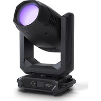
1x S4 Softlight spotlight
1x U-bracket (pre-assembled)
1x Omega double bracket
1x standard diffuser disc (pre-assembled)
1 × 28 ~mm TV spigot incl. M10 fixing screw plus Belleville spring and washer
1x power cable
User manual
INTRODUCTION
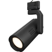
IP65 Softlight
CLS4IP
CONTROL FUNCTIONS:
1CH DIM, 2CH DIM 16bit, 2CH CCT, 4CH CCT, 3CH RGB, 4CH RGBW, 8CH RGBW 16bit, 6CH HSI-CCT, 7CH preset, 7CH RGB-CCT, 7CH direct, 10CH direct-CCT, 10CH HSI-CCT, 16CH direct-CCT, 18CH full access, 6CH x y and 32CH pixel DMX control
DMX512
ArtNet
sACN
W-DMXTM
RDM
Master / slave operation
Standalone functions
FEATURES:
Protection class IP65. RGB+WW colour spectrum. 544 0.5 W LEDs per colour (4 x 544). DMX512. ArtNet sACN. W-DMXTM. 5-pin DMX connections. RJ45 connectors. Blackout button. Button with direct access to CCT mode. 2 freely assignable user buttons. U-bracket and 28mm TV spigot included. One standard diffuser disc included. Wide range of optional accessories.
The spotlight features the RDM standard (Remote Device Management). Remote device management allows the user to view the status and configuration of RDM terminals via an RDM-capable controller. Cameo UNICON also provides access to the entire spotlight menu.
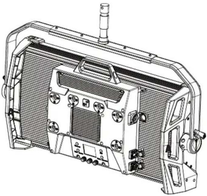
CONNECTIONS, OPERATING AND DISPLAY ELEMENTS
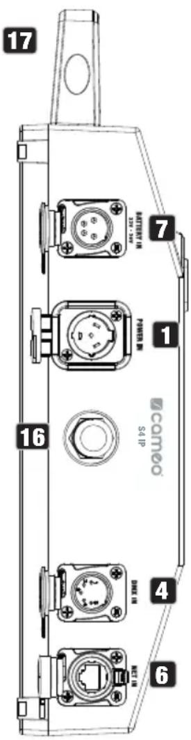


1 POWER IN
IP65 power input socket with rubber sealing cap (compatible with TRUE1). Operating voltage 100-240 V AC/50-60 Hz. Connection via supplied power cable (when not in use, always close with rubber sealing cap).
2 POWER OUT
IP65 power output socket with rubber sealing cap (compatible with TRUE1). Facilitates power supply to other CAMEO spotlights. Ensure that the total current consumption of all connected devices does not exceed the value specified on the device in amperes (A) (when not in use, always close with the rubber sealing cap).
3 DMX IN
Male IP65 5-pin XLR socket for connecting a DMX control device (e.g. DMX console; when not in use, always close with the rubber sealing cap).
DMX OUT
Female IP65 5-pin XLR socket for sending DMX control signal (when not in use, always close with the rubber sealing cap).
5 DATA IN
RJ45 IP65 network connector for connection to an ArtNet or sACN network. When setting up the network, use IP65 cables of category CAT-5e or better (always seal with the rubber sealing cap when not in use).
6 DATA OUT
RJ45 network connection with protection class IP65 for forwarding the control signal. When setting up the network, use IP65 cables of category CAT-5e or better (always seal with the rubber sealing cap when not in use).
BATTERY IN
Male 4-pin XLR socket with IP65 protection rating for connecting external batteries (batteries not included in delivery). A double V-mount adapter with connecting cable is optionally available (article number CLSVMOUNTAP).
8 LC DISPLAY
The LC display shows the currently activated mode (main display), the menu items in the menu and the numerical value or operational status in certain menu items. If there is no input for approx. one minute, the display automatically returns to the main display. Note regarding the main display in operating modes with external control: As soon as the control signal is interrupted, the characters in the display begin to flash. When there is a control signal again, the flashing stops.
9 DIM / SELECT / ENTER
Rotary-push encoder for the adjustment and control of the spotlight.
DIM - In the stand-alone modes CCT, HSI, Direct LED, Colour Coordinates, Gel, User Colour, Play Loop and Light Simulation, the encoder has the function of the master dimmer (rotate encoder).
SELECT - Turn the encoder to SELECT the menu items on the menu level and change a value in a menu item (e.g. DMX start address).
ENTER - 1. Press ENTER to access the menu level to select the mode. 2. You move down one level in the menu structure. 3. You can confirm a value or status change by pressing ENTER, such as changing the DMX start address.
10 The function of the middle push-button rotary encoder (turn and press) is shown in the corresponding menu item in the centre of the display (centre line = turn, bottom line = press).
11 ESC
If the press function of the right push button rotary encoder is not explicitly shown at the bottom right of the display, pressing the encoder has the function of moving up one level in the menu structure.
12BLACKOUT
Shortcut button with blackout function. Press the button to activate blackout. Press the button again to deactivate blackout.
13 CCT
Shortcut button for directly calling up the stand-alone mode CCT.
14 USER 1
With a stand-alone mode, freely assignable button 1 (see menu item Settings -> User Buttons).
15 USER 2
With a stand-alone mode, freely assignable button 2 (see menu item Settings -> User Buttons).
16 W-DMX
Antenna for W-DMXTM control.
17 CARRY HANDLE
Ergonomic carrying handle for convenient transport.
OPERATION
PLEASE NOTE
When the spotlight is started, "Welcome to Cameo", the model name and the software version are briefly shown on the display. After this process, the spotlight is operational and the previously activated operating mode is launched.
MAIN DISPLAY IN DMX MODE
The main display in DMX mode shows the currently set DMX start address, DMX mode and further information (see illustration).

MAIN DISPLAY IN THE ARTNET OR SACN MODE
The main display in ArtNet or sACN mode shows the DMX mode, the currently set DMX start address, the IP address and universe group and the universe (see illustration).
Press encoder = Mode selection
Currently activated operating mode


Press encoder = Open the main menu (Menu)
W-DMXTM
To pair a W-DMX receiver with a W-DMX-compatible transmitter, W-DMX must be switched on in the receiver's settings menu under Wireless Settings (WDMX State -> On), the device must be configured as a receiver (Operating Mode -> Receive) and the Reset command must be executed (Receive Reset -> Yes). The receiver is now in pairing standby and waiting for a pairing request from a transmitter. Start the pairing by selecting Link in the menu of the transmitter and confirming; the pairing now takes place automatically. In the same way, several receivers can be paired simultaneously or one after the other to a transmitter (e.g. for master / slave operation). A W-DMX connection is always maintained until the connection is disconnected by means of the Reset command in the receiver or the Unlink command in the transmitter, regardless of whether a device has been disconnected from the power supply in the meantime.
| AX | ?↓↓ | ↑↓↓ | ×↓↓ | ↓↓ | ↑↑G3 | ↑↑G4S | ×↑↑G3 | ×↑↑G4S |
| W-DMX deactivated | W-DMX as receiver activated, not paired | W-DMX as receiver activated and paired, Transmitter switched off or out of range | W-DMX as receiver activated and paired, no DMX signal | W-DMX as receiver activated and paired, DMX signal is present | W-DMX as transmitter with G3 standard activated, DMX signal is present | W-DMX as transmitter with G4s standard activated, DMX signal is present | W-DMX as transmitter with G3 standard activated, no DMX signal | W-DMX as transmitter with G4s standard activated, no DMX signal |
SETTING DMX START ADDRESS (DMX address)
Starting from the main display, press the right rotary-push encoder to enter the main menu. Rotate the left encoder (SELECT) to select the menu item DMX Address (see left arrow) and confirm by pushing the encoder (ENTER). You can now configure the DMX start address as required by rotating the left encoder (the highest value depends on the selected DMX mode). Confirm the entry by pressing the left encoder (ENTER), which will also automatically return you to the main display and activate DMX mode. At the same time, the following DMX start address (Next Free Address) is displayed for the selected start address plus channel number of the selected DMX mode. The menu item for selecting the desired DMX mode can be reached directly from the DMX Address menu item by pressing the middle rotary-push encoder (DMX mode); the previously set DMX start address is automatically saved.
CONFIGURING DMX MODE
Starting from the main display, press the right rotary-push encoder to enter the main menu (MENU). Rotate the left encoder (SELECT) to select the menu item DMX Mode (see left arrow) and confirm by pushing the encoder (ENTER). You can now select the desired DMX mode by turning the left encoder. Confirm the selection by pressing the left encoder (ENTER), which will also automatically return you to the main display and activate DMX mode. The menu item for setting the desired DMX start address can be reached directly from the DMX Mode menu item by pressing the middle rotary-push encoder (DMX address); the previously selected DMX mode is automatically saved. Tables with the channel assignment of the different DMX modes can be found in these instructions under DMX CONTROL.
ENABLE EXTERNAL CONTROL BY DMX, ARTNET AND SACN
Starting from the main display, press the left push button rotary encoder to access the menu for selecting the mode. Rotate the left encoder (SELECT) to SELECT DMX (see left arrow) and confirm by pressing the left encoder (ENTER). The control protocol preselected in the Protocol menu item in the main menu is now activated (DMX512 / Artnet / sACN).
To configure the two control protocols ArtNet and sACN as desired, press the right encoder (menu), then select Protocol and confirm (Enter). Select the desired protocol, confirm, then select the submenu items for setting and confirm again (see table).
| Protocol ArtNet and sACN | ||
| Select by turning the left encoder, confirm by pressing, change value or status by turning, confirm by pressing. Back with ESC. | ||
| Universe Setting the universe 000-255 | ||
| Universe Group Setting the Universe Group 000 - 127 | ||
| DMX Address Setting the DMX start address 001-512 | ||
| DMX Mode Selecting the DMX mode 1CH dim ... 32CH | pixel | |
| IP Address Setting the IP address:1. Set block with middle encoder2. Set block with right encoderPress middle encoder (Next Range)3. Set block with middle encoder4. Set block with right encoderPress left encoder to save (Enter) | xxx.xxx.xxx.xxx | |
| Subnet Mask Setting the subnet mask:1. Set block with middle encoder2. Set block with right encoderPress middle encoder (Next Range)3. Set block with middle encoder4. Set block with right encoderPress left encoder to save (Enter) | xxx.xxx.xxx.xxx | |
| Signal routing Forwarding the control signal via XLR Out Send to XLR | ||
STANDALONE MODE 'CCT' (Correlated Colour Temperature)
Starting from the main display, press the left push button rotary encoder to access the menu for selecting the mode. Rotate the left encoder (SELECT) to choose CCT (see left arrow) and confirm by pressing the left encoder (ENTER). Set the brightness (DIM), colour temperature (CCT) and colour shade (Tint) by turning the three rotary-push encoders (see illustration).
Rotate encoder = Set brightness (DIM) Press encoder = Mode selection

Rotate encoder = Set tint (Tint)
Press encoder = Open the main menu (Menu)
Rotate encoder = Set colour temperature (CCT)
STANDALONE MODE 'HSI' (Hue - Saturation - Intensity)
Starting from the main display, press the left push button rotary encoder to access the menu for selecting the mode. Rotate the left encoder (SELECT) to choose HSI (see left arrow) and confirm by pressing the left encoder (ENTER). Set the brightness (DIM), colour shade (HUE) and saturation (SAT) by turning the three rotary-push encoders (see illustration).
Rotate encoder = Set brightness (DIM) Press encoder = Mode selection

Rotate encoder = Set saturation (SAT)
Press encoder = Open the main menu (Menu)
Rotate encoder = Set colour shade (HUE)
STANDALONE MODE 'DIRECT LED' (RGBW colour mixing)
Starting from the main display, press the left push button rotary encoder to access the menu for selecting the mode. Turn the left encoder (SELECT) to choose Direct LED (see left arrow) and confirm by pressing the left encoder (ENTER). Now adjust the overall brightness (DIM) and the intensity of R, G, B and W using the three rotary-push encoders (see illustration).
Rotate encoder =
Set overall brightness (DIM)
Press encoder =
Mode selection


Rotate encoder =
Set brightness of G or W
Press encoder =
Open the main menu (Menu)
Rotate encoder =
Set brightness of R or B
Press encoder =
Switch between R+G and B+W (Next Colours)
STANDALONE MODE 'COLOUR COORDINATES'
Starting from the main display, press the left push button rotary encoder to access the menu for selecting the mode. Rotate the left encoder (SELECT) to choose Colour Coordinates (see left arrow) and confirm by pressing the left encoder (ENTER). The overall brightness (DIM) and the x and y coordinates can now be set using the three rotary-push encoders (see illustration).
Rotate encoder =
Set overall brightness (DIM)
Press encoder =
Mode selection


Esc
Rotate encoder =
Set digits 3 and 4 after the decimal point
Press encoder =
Open the main menu (Menu)
Rotate encoder =
Set digits 1 and 2 after the decimal point
Press encoder =
Switch between x and y
(Next coordinate)
STANDALONE MODE 'GEL'
Starting from the main display, press the left push button rotary encoder to access the menu for selecting the mode. Turn the left encoder (SELECT) to choose GEL (see left arrow) and confirm by pressing the left encoder (ENTER). Now set the overall brightness (DIM) using the left encoder and select one of the available Lee filters colour presets (dark magenta to rose pink) using the middle rotary-push encoder (see illustration).
Rotate encoder = Set overall brightness (DIM) Press encoder = Mode selection

Press encoder = Open the main menu (Menu)
Rotate encoder = Select colour preset
STANDALONE MODE 'USER COLOUR'
Starting from the main display, press the left push button rotary encoder to access the menu for selecting the mode. Turn the left encoder (SELECT) to choose User Colour (see left arrow) and confirm by pressing the left encoder (ENTER). Now adjust the brightness (DIM) using the left encoder and select one of the eight user colours (USER_COLOUR_1 to USER_COLOUR_8) using the middle rotary-push encoder (see illustration). The user colours can be edited individually (Main menu -> Edit User Colour).
Rotate encoder = Set overall brightness (DIM) Press encoder = Mode selection
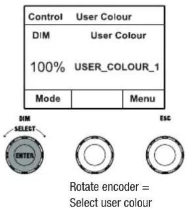
Press encoder = Open the main menu (Menu)
STANDALONE MODE 'EDIT USER COLOURS'
Starting from the main display, press the right rotary-push encoder to enter the main menu (MENU). Rotate the left encoder (SELECT) to choose the Edit User Colour menu item (as indicated by the selection arrow on the left) and confirm by pressing the left encoder (ENTER). You can now select one of the 8 user colours by turning the left encoder and confirming the selection by pressing the left encoder (ENTER).


Now give the user colour an individual name, up to 12 characters long, by turning the left encoder to select a letter, underscore or number for the first character of the name and confirm by pressing the left encoder. This is followed by the input for the second digit and so on. When the name is complete, press the middle encoder (Save&Next) to go to the next processing step. If you press "Save&Next" before selecting a letter, underscore or number for the first digit, the previous name will be retained and you will immediately be taken to the next processing step.
Now decide how you want to create the user colour, select the desired mode by turning the left encoder (SELECT) (CCT, HSI, DIRECT, GEL and Coordinates) and confirm by pressing the left encoder (ENTER).

Now set the desired colour, as described in the instructions for the respective standalone mode, and press the left encoder (ENTER/Save) to confirm.
STANDALONE MODE 'PLAY LOOP'
Starting from the main display, press the left push button rotary encoder to access the menu for selecting the mode. Rotate the left encoder (SELECT) to SELECT Play Loop (see left arrow) and confirm by pressing the left encoder (ENTER). Now select one of the 8 pre-programmed but individually editable colour sequences by turning the left encoder. Confirm your selection by pressing the left encoder (ENTER). The brightness (DIM) of the colour sequence is now set using the left encoder, the step duration (0.1 seconds to 21 minutes and 2 random modes) and the fade time (0 seconds to 18 minutes and 2 random modes) using the middle and right encoders (see illustration). The individual settings and renaming of the colour sequences can be done in the Edit Loop menu item in the main menu.

Rotate encoder = Set brightness (DIM) Press encoder Mode selection
STANDALONE MODE 'EDIT LOOP'
Starting from the main display, press the right rotary-push encoder to enter the main menu (MENU). Turn the left encoder (SELECT) to choose the Edit Loop menu item (as indicated by the selection arrow on the left) and confirm by pressing the left encoder (ENTER). Now you can select one of the 8 colour sequences by turning the left encoder and confirming the selection by pressing the left encoder (ENTER).
| Menu | ||
| Stand AloneEZ RemoteSlaveEdit User Colour▲Edit Loop | ||
| Enter | ESC | |
| Edit Loop | ||
| LOOP_1 LOOP_2 I WARNING LIGHTS TRAFFIC FLASH | ||
| Enter | ESC | |
| Edit LOOP_1 | ||
| Name | ||
| A B C D E F G H I J K L M N O P Q R S T U V W X Y Z _ 0 1 2 3 4 5 6 7 8 9 | ||
| Enter | Save&Next | ESC |
| Edit LOOP_1 | ||
| Step | User Colour | |
| 1 | USER_COLOUR_1 | |
| Enter | Set Colour | ESC |
Now give the colour sequence an individual name, up to 12 characters long, by turning the left encoder to select a letter, underscore or number for the first character of the name and confirm by pressing the left encoder. This is followed by the input for the second digit and so on. When the name is complete, press the middle encoder (Save&Next) to go to the next processing step. If you press "Save&Next" before selecting a letter, underscore or number for the first digit, the previous name will be retained and you will immediately be taken to the next processing step.
Select a step in the 8-step sequence (Step 1 - Step 8) by turning the left encoder to set the colour of the step. Now select one of the colours in the standalone mode User Colour or Blackout or Skip Step by turning the middle encoder. Proceed in the same way to define the colours of the other steps. Complete the process and save the sequence by pressing the left encoder (ENTER).
Starting from the main display, press the left push button rotary encoder to access the menu for selecting the mode. Turn the left encoder (SELECT) to choose Light Simulation (see left arrow) and confirm by pressing the left encoder (ENTER). Now select one of the 8 pre-programmed simulations again by turning the left encoder. Confirm your selection by pressing the left encoder (ENTER). Use the left encoder to adjust the brightness (DIM), step duration (0.1 seconds to 21 minutes and 2 random modes) and fade time (0 seconds to 18 minutes and 2 random modes) using the middle and right encoders as shown.
Rotate encoder = Set brightness (DIM) Press encoder = Mode selection

EZ REMOTE CONTROL VIA CAMEO UNICON (optionally available)
Starting from the main display, press the left push button rotary encoder to access the menu for selecting the mode. Turn the left encoder (SELECT) to choose EZ Remote (see left arrow) and confirm by pressing the left encoder (ENTER). Now set the desired device ID (Fixture ID 1 - 8) by turning the left encoder (SELECT) and confirm by pressing the left encoder (ENTER).
Connect the spotlight and UNICON using a DMX cable, select DMX Control in the UNICON menu, then EZ Remote, and enter the same unit ID. Now control the spotlight using RGB, GEL, CCT or HSI. By assigning different unit IDs, up to eight spotlights (or spotlight groups) can be controlled separately via UNICON.

SLAVE MODE
Starting from the main display, press the left push button rotary encoder to access the menu for selecting the mode. Turn the left encoder (SELECT) to choose Slave (as indicated by selector arrow on left) and confirm by pressing the left encoder (ENTER). Connect the slave and master unit (same model, same software version) using a DMX cable, and activate one of the standalone modes on the master unit. The slave unit will now follow the master unit. Alternatively, the control signal can be transmitted via W-DMX. Activate W-DMX in both the master and slave unit. Configure the master unit as transmitter, the slave unit as receiver and pair the devices (Settings -> Wireless Settings).
SYSTEM SETTINGS
Starting from the main display, press the right push button rotary encoder to access the menu for selecting the mode (menu). Turn the left encoder (SELECT) to choose Settings (see left arrow) and confirm by pressing the left encoder (ENTER).
This will take you to the submenu for setting the submenu items (see table, select by turning the left encoder, confirm with ENTER, change value or status by turning the left encoder, confirm with ENTER).
| Settings | ||||
| Wireless Settings | = W-DMX settings WDMX State On Activate W-DMX | |||
| Dimmer Curve | = Dimmer curve Line | Light intensity increases linearly with DMX value | ||
| Exponential Light intensity can be finely adjusted at lower DMX values and broadly adjusted at higher DMX values | ||||
| Logarithmic Light intensity can be broadly adjusted at lower DMX values and finely adjusted at higher DMX values | ||||
| S-curve Light intensity can be finely adjusted at lower and higher DMX values and broadly adjusted at medium DMX values | ||||
| Dimmer Response | = Dimmer response | LED Lamp responds abruptly to changes in DMX value | ||
| Halogen Light behaves like a halogen spotlight with slight brightness changes | ||||
| Red Shift = | Mimics the colour drift of dimming a halogen spotlight. When dimming the spotlight, the colour temperature changes automatically to increasingly warm white tones and amber (and vice versa). | Off Colour drift is disabled | ||
| Dim to Warm | Colour drift is enabled | |||
| PWM Frequency | = LED PWM frequency | 650 Hz, 1530 Hz, 3600 Hz, 12 kHz, 18.9 kHz, 25 kHz | Select LED PWM frequency | |
| Colour Calibration | = Colour calibration (cross-mode) | RAW R, G, B | and W with maximum value 255 | |
| User Calibration | Individual colour calibration. Cross-mode brightness setting of R, G, B and W with values from 0 - 255. Set R and G with the middle and right encoder, then press the middle encoder (Next Colours) and set B and W again with the middle and right encoder. | |||
| Factory Calibration | Factory calibration of R, G, B and W | |||
| Smart Calibration | Merging factory and RAW calibration | |||
| Autolock = Automatic locking of the controls | On Automatic | locking of the controls after approximately 1 minute of inactivity. Display shown upon attempted use: "Locked!" Unlock: Simultaneously press the centre and right encoders for approx. 5 sec. | ||
| Off Automatic | locking of the controls is disabled | |||
| Fan = Fan control Auto Automatic | fan speed control | |||
| Off Deactivated | fan with greatly reduced brightness | |||
| Constant Low | Constantly low fan speed with reduced brightness, if necessary | |||
| Constant Medium | Constant average fan speed with reduced brightness, if necessary | |||
| Constant High | Constant high fan speed | |||
| Factory Reset | = Reset settings Reset | Now? Except User Colour_ Loops | Reset to factory settings (except user colours and loops): Perform reset with ENTER, cancel with ESC | |
| Reset UC_Loops | = Reset user colours and loops | Reset user colour_loops | Reset the user colours and loops to factory settings: Perform reset with ENTER, cancel with ESC | |
| User buttons | = Assign one of the stand-alone modes (plus EZ Remote and Mode Selection) to user buttons 1 and 2 | User button 1 | EZ Remote Mode Selection HSI Direct Colour Coordinates GEL User Colour Play Loop Light Simulation | EZ Remote = Control via CAMEO UNICON (optionally available) Mode Selection = Activate stand-alone modes one after the other by repeatedly pressing the user button |
| User button 2 | “ | |||
| Service = For service purposes only | ||||
SYSTEM INFORMATION (System Info)
Starting from the main display, press the right push button rotary encoder to access the menu for selecting the mode (menu). Rotate the left encoder (SELECT) to SELECT System Info (see left arrow) and confirm by pressing the left encoder (ENTER). This will take you to the submenu for calling up the system information (see table, selection by turning the left encoder).
PSFASNE
| Main CPU Vx.xx | |
| DRV CPU Vx.xx | |
| LED temp. xx°F xx°C | |
| Op. hours xxxxxx:xx h | |
| Display Always on/off after 20 s | |
| Signal Fail Hold / Blackout / User Colour 8 / Fade Out 10s | |
| Dim Curve Linear / Exponential / Logarithmic / S-Curve | |
| Dim Response LED / Halogen | |
| Red Shift Off / Dim to Warm | |
| PWM 650 Hz / 1530 Hz / 3600 Hz / 12 kHz / 18.9 kHz / 25 kHz | |
| Calibr. RAW / User / Factory / Smart | |
| User calibration R=000-255 | |
| User calibration G=000-255 | |
| User calibration B=000-255 | |
| User calibration W=000-255 | |
| Auto Lock Off / On | |
| Fan Auto / Off / Constant Low / Constant Medium / Constant High | |
| WDMX Off / On | |
| User button 1 | EZ Remote / Mode Selection / HSI / Direct / Colour Coordinates GEL / User Colour / Play Loop / Light Simulation |
| User button 2 | EZ Remote / Mode Selection / HSI / Direct / Colour Coordinates GEL / User Colour / Play Loop / Light Simulation |
| RDM UID xx xx xx xx xx xx | xx |
| MAC Addr. | xx:xx:xx:xx:xx:xx |
In order to be able to access all menu items in the spotlight via the Fixture menu using the Cameo UNICON DMX/RDM controller, the menu items Stand Alone (with all Stand Alone modes), EZ Remote and Slave are also in the main menu, except in the Mode menu.
MOUNT TV SPIGOT ON U-BRACKET
There is one bolt each on the left and right next to the M10 screw thread in the TV spigot. Insert the two bolts into the holes to the left and right of the screw hole in the U-bracket and screw the TV spigot to the U-bracket using the M10 screw, Belleville spring and washer (see illustration).

- Similar to image -
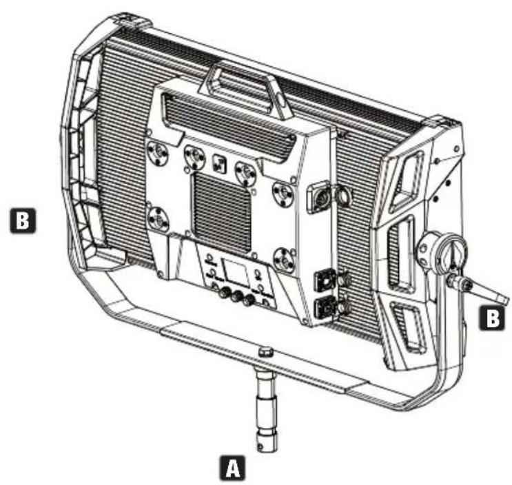
STAND MOUNTING

HAZARD: Overhead mounting requires extensive experience, including the calculation of the load limit values of the installation material and regular safety inspection of all installation materials and spotlights. If you do not have these qualifications, do not attempt to perform an installation yourself. Refer instead to a qualified professional. There is a risk that devices that are incorrectly mounted and secured may come loose and fall down. This can cause serious injury or death.
Use the 28 mm TV spigot previously mounted on the U-bracket to mount the stand (Fig. A). Use a suitable stand and observe the manufacturer's instructions (maximum load capacity, vertical installation on a level surface, etc.). To adjust the dispersion direction in the vertical plane, slightly loosen the clamps mounted on the U-bracket (Fig. B), adjust the desired beam direction and tighten the clamps again.
- Similar to image -
USE TV SPIGOT FOR TRUSS MOUNTING

HAZARD: Overhead mounting requires extensive experience, including the calculation of the limit values for load, the installation materials and regular safety inspection of all installation materials and spotlights. If you do not have these qualifications, do not attempt to perform an installation yourself. Refer instead to a qualified professional. There is a risk that devices that are incorrectly mounted and secured may come loose and fall down. This can cause serious injury or death.
The 28 mm TV spigot previously mounted on the U-bracket can also be used for truss mounting. Use a suitable fastener and make sure it is firmly attached. To adjust the dispersion direction in the vertical plane, slightly loosen the clamps mounted on the U-bracket, set the desired dispersion direction and tighten the clamps again. Secure the spotlight to the side handle recesses using a suitable safety cable (Fig. A).
- Similar to image -
OMEGA BRACKET
The Omega double bracket is included in the spotlight's scope of delivery.

HAZARD: Overhead mounting requires extensive experience, including the calculation of the load limit values of the installation material and regular safety inspection of all installation materials and spotlights. If you do not have these qualifications, do not attempt to perform an installation yourself. Refer instead to a qualified professional. There is a risk that devices that are incorrectly mounted and secured may come loose and fall down. This can cause serious injury or death.
Truss installation: First mount two suitable truss clamps (optionally available) on the left and right of the Omega bracket (Fig. A) and then both together on the spotlight (Fig. B). Turn the four locking levers clockwise about a quarter turn until they stop. Make sure that all connections are secure and then fasten the spotlight to the side handle recesses with a suitable safety cable (Fig. C).


- Similar to image -
The Omega double bracket also serves as a mounting base for the optionally available centre yoke and V-mount adapter accessories (see OPTIONAL ACCESSORIES).
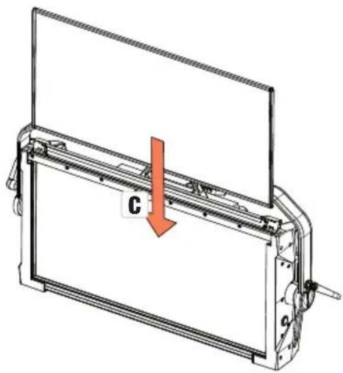
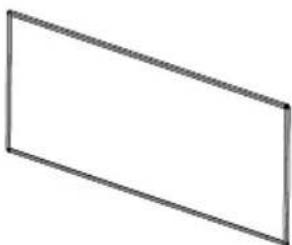
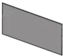
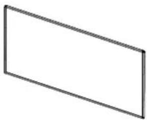
DIFFUSER DISC
A standard diffuser disc is included. A locking lever for the cover rail is located on the top edge of the spotlight on the left and right (Fig. A and detailed view). Push the levers towards the centre of the housing and fold the cover rail upwards (Fig. B).


Now insert the diffuser disc into the rear, wide grooves of the installation compartment from above (Fig. C and detailed view).

- Similar to image -
Now fold the cover rail back down to close the installation compartment (Fig. D). The two locking levers must then be pushed back towards the edge of the housing. During the process, ensure that the levers engage correctly again and that the diffuser disc is secured against falling out.

- Similar to image -

Please note: A diffuser disc (or the intensifier, optionally available) can also be installed in combination with one of the optionally available straightening grids and the optionally available dark filter (straightening grid + dark filter: narrow groove, diffuser discs + intensifier: wide groove). The optionally available barndoor can also be mounted on the spotlight.
OPTIONAL ACCESSORIES
CLS4IPBARNDOOR
4-way barndoor

CLS4IPINTENSIFIER
Filter disc for narrow beam angles and increased illumination intensity
CLSCENTERYOKE
28 mm TV spigot with ball joint

CLS4IPDARKFILTER
Filter disc for dark front
CLS4IPHC30
Straightening grid for narrow beam angles

CLSVMOUNTAP
Double V-mount adapter

- Similar to image -
CLS4IPHDFILTER
Filter disc for high diffusion
CLS4IPHC60
Straightening grid for limited beam angle

CLS4IPPOYOKE
Pole-operated mounting bracket

CARE, MAINTENANCE AND REPAIR
In order to ensure the long-term, proper functioning of the device, it must be regularly cleaned and, if necessary, maintained. The maintenance requirement depends on the intensity of use and the environment in which it is used. We generally recommend a visual inspection each time before putting into operation. Furthermore, we recommend carrying out all the applicable maintenance measures specified below once every 500 operating hours or, in the case of a lower intensity of use, at the latest after one year. Warranty claims may be limited in the event of defects resulting from inadequate maintenance.
CARE (CARRIED OUT BY USER)

WARNING! Before carrying out any care or maintenance, the power supply – and, if possible, all device connections – must be disconnected.

NOTE! Improper care can lead to impairment of the device or even its destruction.
- Housing surfaces must be cleaned with a clean, damp cloth. In doing so, ensure that no moisture can penetrate into the device.
- Air inlets and outlets must be regularly cleaned of dust and dirt. If compressed air is used, make sure that damage to the device is prevented (e.g. fans must be blocked in this case).
- Lines and plug contacts must be cleaned regularly and dust and dirt must be removed.
- In general, no cleaning agents or abrasive agents may be used, otherwise the surface finish may be damaged.
- Devices must generally be stored dry and protected from dust and dirt.
MAINTENANCE AND REPAIR (BY QUALIFIED PERSONNEL ONLY)

HAZARD! There are live components in the device. Even after disconnecting the mains connection, there may still be residual voltage in the device, for example, due to charged capacitors.

PLEASE NOTE! There are no user-serviceable assemblies in the device.

PLEASE NOTE! Maintenance and repair work may only be carried out by qualified specialist personnel authorised by the manufacturer. If in doubt, consult the manufacturer.

PLEASE NOTE! Improperly performed maintenance work may affect the warranty claim.
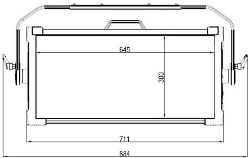
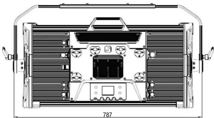
DIMENSIONS (mm)

TECHNICAL DATA
| Product number: CLS4IP | |
| Product type: LED spotlight | |
| Type: Softlight | |
| Colour spectrum: RGBWW | |
| Number of LEDs per colour: 544 | |
| LED type: 0.5 W single-colour LEDs | |
| LED PWM frequency: 650 Hz, 1530 Hz, 3600 Hz, 12 kHz, 18.9 kHz, 25 kHz (adjustable) | |
| Beam angle (standard diffuser): 1/2 peak 101.5° 1/10 peak 159° | |
| Control signal input: 5-pin XLR male, RJ45 | |
| Control signal output: 5-pin XLR female, RJ45 | |
| DMX functions: Dimmer, Strobe, Red, Green, Blue, White, Hue, Saturation, x + y-coordinates, Colour Temperature, Tint, Colour Presets, Colour Presets Crossfade, Effect Macro, Effect Macro Speed, Device Settings | |
| Control protocols: DMX512, W-DMXTM, ArtNet, sACN, RDM | |
| Standalone functions: Direct, CCT, HSI, User Colour, GEL, xy-coordinates, Light Simulation, Loop | |
| Operating controls: | 3x turn-push encoder + 4x shortcut buttons |
| Operating voltage: | 100–240 V AC/50–60 Hz |
| Max. Output current POWER OUT: | 10 A |
| Battery Input | 4-pin XLR |
| Battery operating voltage | 23–36 V |
| Power consumption: | 460 W |
| Illumination intensity @ 5 m (standard diffuser) | 420 lx |
| Illumination intensity @ 10 m (standard diffuser) | 105 lx |
| Luminous flux: @RGBW | 25,000 lm |
| Temperature range: | 1,800K–10,000 K |
| Ra | >92 |
| REC2020 cover | 85.7% |
Power supply connection: True 1 compatible sockets
IP protection class IP65
Ambient temperature (in operation): -15^ to 45^
Minimum distance to illuminated surface 0.5m
Minimum distance to normally flammable 0.5 m materials
Housing colour: Black
Housing material: Magnesium alloy
Housing cooling: Temperature-controlled fan
Dimensions (W x H x D, including mounting 884 x 442 x 153 mm bracket):
Weight (without mounting bracket and diffuser): 15.1 kg
Accessories (included): 1x power cable
1x U-bracket
1x 28 mm TV spigot
1x standard diffuser
Accessories (optional): Honey Comb (30^ / 60^)
Intensifier
Barndoor
Heavy Diffusor
Dark Filter
Center Yoke
V-Mount Double Adaptor
P.O. Yoke
EXPLANATION OF IP PROTECTION CLASS
- An IP rating only reflects protection from solid objects and water. It does not describe general weather resistance, such as protection from UV radiation and temperature, etc.
- The first identification digit indicates protection from dust, solid objects and contact:
| IP2X Protected against solid foreign bodies ≥ 12.5 mm in diameter |
| IP3X Protected against solid foreign bodies ≥ 2.5 mm in diameter |
| IP4X Protected against solid foreign bodies ≥ 1.0 mm in diameter |
| IP5X Protected against dust in harmful quantities and completely protected against contact |
| IP6X Are dust-tight and completely protected against contact |
- The second identification digit indicates protection from water:
| IPX0 No | protection |
| IPX1 Protection against dripping water | |
| IPX2 Protection against dripping water when the device is tilted up to 15° | |
| IPX3 Protection against falling spray water up to 60° from the vertical | |
| IPX4 Protection against splashing water on all sides | |
| IPX5 Protection against water jets (nozzle) from any angle | |
| IPX6 Protection against strong water jets | |
| IPX7 Protection against temporary immersion | |
- In addition, some device-specific measures, such as covers and sealing caps, are necessary in order to achieve the specified protection class (e.g. protective caps on unused connections).
MINIMUM DISTANCE TO ILLUMINATED SURFACE

This symbol with distance specification in metres (m) indicates the minimum distance between the light head and the illuminated surface. In this example, the distance is 0.5m . The value applicable for this unit can be found in the technical data in this manual and the imprint on the unit housing!
MINIMUM DISTANCE TO NORMALLY FLAMMABLE MATERIALS

This symbol with distance specification in metres (m) indicates the minimum distance between the light head and normally flammable materials. In this example, the distance is 0.5m . The value applicable for this unit can be found in the technical data in this manual!
DISPOSAL

Packaging:
- Packaging can be fed into the reusable material cycle using the usual disposal methods.
- Please separate the packaging in accordance with the disposal laws and recycling regulations in your country.

Device:
- This device is subject to the European Directive on Waste Electrical and Electronic Equipment, as amended. WEEE Directive Waste Electrical and Electronic Equipment. Old appliances do not belong in household waste. The old device must be disposed of via an approved disposal company or a municipal disposal facility. Please observe the applicable regulations in your country!
- Observe all disposal laws applicable in your country.
- As a private customer, you can obtain information on environmentally-friendly disposal options from the seller of the product or the appropriate regional authorities.

Batteries:
- Batteries should not be disposed of in household waste. Batteries must be disposed of via an approved disposal company or a municipal disposal facility.
- Observe all disposal laws and regulations applicable in your country.
- As a private customer, you can obtain information on environmentally-friendly disposal options from the seller of the product or the appropriate regional authorities.
- Devices with batteries that cannot be removed by the user must be taken to a collection point for electrical devices.
MANUFACTURER'S DECLARATIONS
MANUFACTURER'S WARRANTY & LIMITATION OF LIABILITY
Adam Hall GmbH, Adam-Hall-Str. 1, 61267 Neu Anspach, Germany / E-mail Info@adamhall.com / +49 (0)6081 / 9419-0.
Our current warranty conditions and limitation of liability can be found at:
https://cdn-shop.adamhall.com/media/pdf/Manufacturers-Declarations-CAMEO_DE_EN_ES_FR.pdf.
Contact your distribution partner for service.
UKCA- CONFORMITY
Hereby, Adam Hall Ltd. declares that this product meets the following guidelines (where applicable)
Electrical Equipment (Safety) Regulations 2016
Electromagnetic Compatibility Regulations 2016 (SI 2016/1091)
The Restriction of the Use of Certain Hazardous Substances in Electrical and Electronic Equipment Regulation 2012 (SI 2012/3032)
Radio Equipment Regulations 2017(SI 2016/2015)
UKCA-DECLARATION OF CONFORMITY
Products that are subject to Electrical Equipment(Safety)Regulation 2016, EMC Regulation 2016 or RoHS Regulation can be requested at info@adamhall.com.
Products that are subject to the Radio Equipments Regulations 2017 (SI2017/1206) can be downloaded from www.adamhall.com/compliance/
FCC STATEMENT
This equipment has been tested and found to comply with the limits for a Class B digital device, pursuant to part 15 of the FCC Rules. These limits are designed to provide reasonable protection against harmful interference in a residential installation. This equipment generates, uses and can radiate radio frequency energy and, if not installed and used in accordance with the instructions, may cause harmful interference to radio communications. However, there is no guarantee that interference will not occur in a particular installation. If this equipment does cause harmful interference to radio or television reception, which can be determined by turning the equipment off and on, the user is encouraged to try to correct the interference by one or more of the following measures:
- Reorient or relocate the receiving antenna.
- Increase the separation between the equipment and receiver.
- Connect the equipment into an outlet on a circuit different from that to which the receiver is connected.
- Consult the dealer or an experienced radio/TV technician for help.
Caution: Any changes or modifications to this device not explicitly approved by manufacturer could void your authority to operate this equipment.
This device complies with part 15 of the FCC Rules. Operation is subject to the following two conditions: (1) This device may not cause harmful interference, and (2) this device must accept any interference received, including interference that may cause undesired operation.
RF EXPOSURE INFORMATION
This equipment complies with FCC radiation exposure limits set forth for an uncontrolled environment. This equipment should be installed and operated with minimum distance 20cm between the radiator and your body.
SUBJECT TO MISPRINTS AND ERRORS, AS WELL AS TECHNICAL OR OTHER MODIFICATIONS!
DEUTSCH
STANDALONE BETRIEBSART CCT (Correlated Colour Temperature)
| Edit LOOP_1 | ||
| Name | ||
| A B C D E F G H I J K L M N O P Q R S T U V W X Y Z _ 0 1 2 3 4 5 6 7 8 9 | ||
| Enter | Save&Next | ESC |
| Edit LOOP_1 | ||
| Step | User Colour | |
| 1 | USER_COLOUR_1 | |
| Enter | Set Colour | ESC |
| System Info | |
| Main CPU Vx.xx | |
| DRV CPU Vx.xx | |
| LED Temp. xx°F xx°C | |
| Op. Hours xxxx:xx h | |
| Display Always On / Off after 20s | |
| Signal Fail Hold / Blackout | / User Colour 8 / Fade Out 10s |
| Dim Curve Linear / Exponential / Logarithmic / S-Curve | |
| Dim Response LED / Halogen | |
| Red-Shift Off / Dim to Warm | |
| PWM 650Hz / 1530Hz / 3600Hz / 12kHz / 18.9kHz / 25kHz | |
| Calibr. RAW / User / Factory / Smart | |
| User-Calibration R=000 - | 255 |
| User-Calibration G=000 - | 255 |
| User-Calibration B=000 - | 255 |
| User-Calibration W= | 000 - 255 |
| Auto Lock Off / On | |
| Fan | Auto / Off / Constant Low / Constant Medium / Constant High |
| WDMX | Off / On |
| User Button 1 | EZ Remote / Mode Selection / HSI / Direct / Colour Coordinates GEL / User Colour / Play Loop / Light Simulation |
| User Button 2 | EZ Remote / Mode Selection / HSI / Direct / Colour Coordinates GEL / User Colour / Play Loop / Light Simulation |
| RDM UID xx xx xx xx xx xx | xx |
| MAC Addr. | xx:XX:XX:XX:XX:XX |
HINWEIS
V-Mount Double Adaptor
P.O. Yoke
https://cdn-shop.adamhall.com/media/pdf/Manufacturers-Declarations-CAMEO_DE_EN_ES_FR.pdf.
MODE STANDALONE CCT (Correlated Colour Temperature)
MODE STANDALONE HSI (Hue - Saturation - Intensity)
| Edit Loop | ||
| LOOP_1 LOOP_2 I WARNING LIGHTS TRAFFIC FLASH | ||
| Enter | ESC | |
| Edit LOOP_1 | ||
| Name | ||
| A B C D E F G H I J K L M N O P Q R S T U V W X Y Z _ 0 1 2 3 4 5 6 7 8 9 | ||
| Enter | Save&Next | ESC |
| Edit LOOP_1 | ||
| Step | User Colour | |
| 1 | USER_COLOUR_1 | |
| Enter | Set Colour | ESC |
| System Info | |
| Main CPU Vx.xx | |
| DRV CPU Vx.xx | |
| LED Temp. xx°F xx°C | |
| Op. Hours xxxx:xx h | |
| Écran Always On / Off after 20s | |
| Signal Fail Hold / Blackout / User Colour 8 / Fade Out 10 s | |
| Dim Curve Linear / Exponential / Logarithmic / S-Curve | |
| Dim Response LED/halogène | |
| Red-Shift Off / Dim to Warm | |
| PWM 650 Hz / 1530Hz / 3600Hz / 12kHz / 18.9kHz / 25kHz | |
| Calibr. RAW / User / Factory / Smart | |
| User-Calibration R=000 - 255 | |
| User-Calibration G=000 - 255 | |
| User-Calibration B=000 - 255 | |
| User-Calibration W=000 - 255 | |
| Auto Lock Off / On | |
| Fan Auto / Off / Constant Low / Constant Medium / Constant High | |
| WDMX | Off / On |
| User Button 1 | EZ Remote/Mode Selection/HSI/Direct/Colour CoordinatesGEL/User Colour/Play Loop/Light Simulation |
| User Button 2 | EZ Remote/Mode Selection/HSI/Direct/Colour CoordinatesGEL/User Colour/Play Loop/Light Simulation |
| UID RDM xx xx xx xx xx xx | xx |
| MAC Addr. | xx:xx:xx:xx:xx:xx |
REMARQUE
ACCESSIONS EN OPTION
CLS4IPBARNDOOR
https://cdn-shop.adamhall.com/media/pdf/Manufacturers-Declarations-CAMEO_DE_EN_ES_FR.pdf.
Directive CEM (2014/30/UE)
RoHS (2011/65/UE)
RED (2014/53/UE)
Déclaration de CONFORMITE CE
MODO OPERativo AUTONOMO DE CCT (Correlated Colour Temperature)
| Main CPU Vx.xx | |
| DRV CPU Vx.xx | |
| LED Temp. xx°F xx°C | |
| Op. Hours xxxxx:xx h | |
| Display Always On / Off after 20s | |
| Signal Fail Hold / Blackout | / User Colour 8 / Fade Out 10s |
| Dim Curve Linear / Exponential / Logarithmic / S-Curve | |
| Dim Response LED / Halogen | |
| Red-Shift Off / Dim to Warm | |
| PWM 650 Hz / 1530 Hz / 3600 Hz / 12 kHz / 18,9 kHz / 25 kHz | |
| Calibr. RAW / User / Factory / Smart | |
| User-Calibration R=000 - | 255 |
| User-Calibration G=000 - | 255 |
| User-Calibration B=000 - | 255 |
| User-Calibration W=000 - | 255 |
| Auto Lock Off / On | |
| Fan Auto / Off / Constant Low / Constant Medium / Constant High | |
| WDMX | Off / On |
| User Button 1 | EZ Remote / Mode Selection / HSI / Direct / Colour Coordinates GEL / User Colour / Play Loop / Light Simulation |
| User Button 2 | EZ Remote / Mode Selection / HSI / Direct / Colour Coordinates GEL / User Colour / Play Loop / Light Simulation |
| RDM UID xx xx xx xx xx xx | xx |
| MAC Addr. | xx:XX:XX:XX:XX:XX |
NOTA
V-Mount Double Adaptor
P.O. Yoke
EXPLICACION SOBRE LA CLASE DE PROTECCION IP
https://cdn-shop.adamhall.com/media/pdf/Manufacturers-Declarations-CAMEO_DE_EN_ES_FR.pdf.
TRYB PRACY STANDALONE CCT (Correlated Colour Temperature)
TRYB PRACY STANDALONE HSI (Hue - Saturation - Intensity)
| Edit Loop | ||
| LOOP_1 LOOP_2 I WARNING LIGHTS TRAFFIC FLASH | ||
| Enter | ESC | |
| Edit LOOP_1 | ||
| Name | ||
| ABCDEFGHIJKLMNOPQRSTUWXYZ0123456789 | ||
| Enter | Save&Next | ESC |
| Edit LOOP_1 | ||
| Step | User Colour | |
| 1 | USER_COLOUR_1 | |
| Enter | Set Colour | ESC |
V-Mount Double Adaptor
P.O. Yoke
OBJASNIENIA DOTYCZACE STOPNIA OCHRONY IP
V-Mount Double Adaptor
P.O. Yoke
https://cdn-shop.adamhall.com/media/pdf/Manufacturers-Declarations-CAMEO DE EN ES FR.pdf.
| 7 | ||||||||
| 10 | ||||||||
| Device Set- (please read 138+139) | 120-121 PMW 1(650 Hz)(hold 3s) | 122-123 PWM 2(1530 Hz)(hold 3s) | 124-125 PWM 3(3600 Hz)(hold 3s) | 126-127 PWM 4(12 kHz)(hold 3s) | 128-129 PWM 5(18.9 kHz)(hold 3s) | 130-131 PWM 6(25 kHz)(hold 3s) | 134-135 Calibrated (hold 3s) | 132-133 RAW (hold 3s) |
| Remark 1' | 136-137 User Calibrated (hold 3s) | 134-135 Calibrated (hold 3s) | 132-133 RAW (hold 3s) | 131-132 RAW (hold 3s) | 134-135 Calibrated (hold 3s) | 131-132 RAW (hold 3s) | 132-133 RAW (hold 3s) | 131-132 RAW (hold 3s) |
| 140-141 Display on (hold 3s) | 142-143 Display off (hold 3s) | 144-146 No function | 144-146 No function | 144-146 No function | 144-146 No function | 144-146 No function | 144-146 No function | 144-146 No function |
| 164-165 | Dimmer Curve Linear | Dimmer Curve Linear | Dimmer Curve Linear | Dimmer Curve Exponent- | Dimmer Curve Exponent- | Dimmer Curve Exponent- | Dimmer Curve Exponent- | Dimmer Curve Exponent- |
| 166-167 | Dimmer Curve Logarithm- | Dimmer Curve Logarithm- | Dimmer Curve Logarithm- | Dimmer Curve Logarithm- | Dimmer Curve Logarithm- | Dimmer Curve Logarithm- | Dimmer Curve Logarithm- | Dimmer Curve Logarithm- |
| 168-169 | mic (hold 3s) | mic (hold 3s) | mic (hold 3s) | mic (hold 3s) | mic (hold 3s) | mic (hold 3s) | mic (hold 3s) | mic (hold 3s) |
| 170-171 | Dimmer Curve S-Curve | Dimmer Curve S-Curve | Dimmer Curve S-Curve | Dimmer Curve S-Curve | Dimmer Curve S-Curve | Dimmer Curve S-Curve | Dimmer Curve S-Curve | Dimmer Curve S-Curve |
| 172-239 | No function | No function | No function | No function | No function | No function | No function | No function |
| 240-241 | Default set (except Default set (except | Default set (except | Default set (except | Default set (except | Default set (except | Default set (except | Default set (except | |
| 242-243 | Default set (except | Default set (except | Default set (except | Default set (except | Default set (except | Default set (except | Default set (except | |
| 242-243 | Default set (except | Default set (except | Default set (except | Default set (except | Default set (except | Default set (except | Default set (except | |
| 242-243 | Default set (except | Default set (except | default set (except | default set (except | default set (except | default set (except | default set (except | |
| 242-243 | Default set (except | Default set (except | default set (except | default set (except | default set (except | default set (except | default set (except | |
| 242-243 | Default set (except | Default set (except | default set (except | default set (except | default set (except | default set (except | default set (except | |
| 242 - 243 | Default set (except | Default set (except | default set (except | default set (except | default set (except | default set (except | default set (except | |
| 242-243 | Default set (except | Default set (except | default set (except | default set (except | default set (except | default set (except | default set (except | |
| 242-243 | Default set (except | default set (except | default set (except | default set (except | default set (except | default set (except | default set (except | |
| 242-243 | Default set (except | Default set (except | default set (except | default set (except | default set (except | default set (except | default set (except | |
| 242-243 | Default set (except | Default set (except | default set (except | 170-171 | Dimmer Curve S-Curve | Dimmer Curve S-Curve | Dimmer Curve S-Curve | Dimmer Curve S-Curve |
| 16Ch Direct CCT | 18 Ch Full Access | Function Values Sub-Group | ||||
| 1 1 Dimmer 000 - 255 0% to 100% Dimmer | ||||||
| 2 2 Dimmer fine 000 - 255 0% to 100% | ||||||
| 3 | 3 | Strobe functions | 000 - 005 Strobe open | Multifunctional Strobe | ||
| 006 - 010 Strobe closed | ||||||
| 011 - 022 | Ramp up/down, slow -> fast | |||||
| 023 - 033 | Ramp up/down random, slow->fast | |||||
| 034 - 045 Ramp up, slow -> fast | ||||||
| 046 - 056 | Ramp up random, slow -> fast | |||||
| 057 - 068 Ramp down, slow -> fast | ||||||
| 069 - 079 | Ramp down random, slow -> fast | |||||
| 080 - 102 | Random Strobe effect, slow -> fast | |||||
| 103 - 127 | Strobe Break effect, 5s....1s (short burst with break) | |||||
| 128 - 250 | Strobe slow -> fast <1Hz - 20Hz | |||||
| 251 - 255 Strobe open | ||||||
| 4 4 Red 000 - 255 0% to 100% | Red | |||||
| 5 5 | Red fine 000 - 255 0% to 100% | |||||
| 6 6 | Green 000 - 255 0% to 100% | Green | ||||
| 7 7 | Green fine 000 - 255 0% to 100% | |||||
| 8 8 | Blue 000 - 255 0% to 100% | Blue | ||||
| 9 9 | Blue fine 000 - 255 0% to 100% | |||||
| 10 | 10 | White | 000 - 255 0% to 100% | White | ||
| 11 | 11 | White fine | 000 - 255 0% to 100% | |||
| 12 | 12 | Colour Temperature (affects RGBW) | 000 + 005 No function | CCT | ||
| 006 + 006 Warm white | ||||||
| 007 + 046 Warm white -> 2700K | ||||||
| 047 + 047 Bulb White (2700K) | ||||||
| 048 + 087 2700K -> 3200K | ||||||
| 088 + 088 Halogen White (3200K) | ||||||
| 089 + 128 3200K -> 4000K | ||||||
| 129 + 129 Neutral White (4000K) | ||||||
| 130 + 169 4000K -> 5600K | ||||||
| 170 + 170 Studio White (5600K) | ||||||
| 171 + 210 5600K -> 6500K | ||||||
| 211 + 211 Daylight White (6500K) | ||||||
| 212 + 251 6500K -> Cold Daylight | ||||||
| 252 + 255 Cold Daylight | ||||||
| 13 | 13 | Tint (affects Colour Temperature) | 000 + 000 Off | Tint | ||
| 001 + 127 Magenta -> Neutral | ||||||
| 128 + 128 neutral | ||||||
| 129 + 255 Neutral -> Green | ||||||
| 14 14 | Colour Pre-sets(override RGBW,Colour Tem-perature) | Lee Filter No. | ||||
| 000 | - | 005 no function | ||||
| 006 | - | 009 46 Dark Magenta | ||||
| 010 | - | 013 29 Plasa Red | ||||
| 014 | - | 017 26 Bright Red | ||||
| 018 | - | 021 127 Smokey Pink | ||||
| 022 | - | 025 36 Medium Pink | ||||
| 026 | - | 029 19 Fire | ||||
| 030 | - | 033 135 Deep Golden Amber | ||||
| 034 | - | 037 778 Millennium Gold | ||||
| 038 | - | 041 21 Gold Amber | ||||
| 042 | - | 045 157 Pink | ||||
| 046 | - | 049 110 Middle Rose | ||||
| 050 | - | 053 109 Light Salmon | ||||
| 054 | - | 057 35 Light Pink | ||||
| 058 | - | 061 134 Golden Amber | ||||
| 062 | - | 065 17 Surprise Peach | ||||
| 066 | - | 069 746 Brown | ||||
| 070 | - | 073 105 Orange | ||||
| 074 | - | 077 20 Medium Amber | ||||
| 078 | - | 081 768 Egg Yolk Yellow | ||||
| 082 | - | 085 15 Deep Straw | ||||
| 086 | - | 089 767 Oklahoma Yellow | ||||
| 090 | - | 093 101 Yellow | ||||
| 094 | - | 097 100 Spring Yellow | ||||
| 098 | - | 101 88 Lime Green | ||||
| 102 | - | 105 121 LEE Green | ||||
| 106 | - | 109 738 Jas Green | ||||
| 110 | - | 113 89 Moss Green | ||||
| 114 | - | 117 139 Primary Green | ||||
| 118 | - | 121 124 Dark Green | ||||
| 122 | - | 125 323 Jade | ||||
| 126 | - | 129 354 Special Steel Blue | ||||
| 130 | - | 133 116 Medium Blue-Green | ||||
| 134 | - | 137 183 Moonlight Blue | ||||
| 138 | - | 141 132 Medium Blue | ||||
| 142 | - | 145 119 Dark Blue | ||||
| 146 | - | 149 716 Mikkel Blue | ||||
| 150 | - | 153 71 Tokyo Blue | ||||
| 154 | - | 157 181 Congo Blue | ||||
| 158 | - | 161 799 Special KH Lavender | ||||
| 162 | - | 165 707 Ultimate Violet | ||||
| Roscolux Filter No. |
| 46 |
| 26 |
| 22 |
| 38 |
| 15 |
| 15 |
| 313 |
| 312 |
| 10 |
| 388 |
| 4460 |
| 89 |
| 90 |
| 393 |
| 370 |
| 95 |
| 77 |
| 74 |
| 384 |
| 382 |
| 382 |
| 382 |
| 14 14 | Colour Pre-sets(override RGBW,Colour Tem-perature) | 166 - 169 | 343 Special Medium Lavender | Colour Presets | |
| 170 - 173 798 | Chrysalis Pink | ||||
| 174 - 177 701 | Provence | ||||
| 178 - 181 797 | Deep Purple | ||||
| 182 - 185 48 Rose Purple | |||||
| 186 - 189 345 | Fuchsia Pink | ||||
| 190 - 193 795 | Magical Magenta | ||||
| 194 - 197 128 | Bright Pink | ||||
| 198 - 201 2 Rose Pink | |||||
| 202 - 207 User Colour_1 | |||||
| 208 - 213 User Colour_2 | |||||
| 214 - 219 User Colour_3 | |||||
| 220 - 225 User Colour_4 | |||||
| 226 - 231 User Colour_5 | |||||
| 232 - 237 User Colour_6 | |||||
| 238 - 243 User Colour_7 | |||||
| 244 - 249 User Colour_8 | |||||
| 250 - 255 no function | |||||
| 15 15 | Colour Preset Crossfade(Affects Colour Tem-perature, HSI too) | 000 - 005 0s | Colour Presets | ||
| 006 - 105 0,1s | - 10s (0,1s Steps) | ||||
| 106 - 214 11s | - 119s (1s Steps) | ||||
| 215 - 244 2m | 4m50s (10s Steps) | ||||
| 245 - 255 5m | - 15m (1m Steps) | ||||
| 16 Effect Macro | 000 - 005 No Function | Light simulat- tion | |||
| 006 - 039 Colour Chase | |||||
| 040 - 068 Police Car | |||||
| 069 - 096 Firetruck | |||||
| 097 - 125 Fire | |||||
| 126 - 154 Clouds | |||||
| 155 - 182 Fireworks | |||||
| 183 - 211 Paparazzi | |||||
| 212 - 240 Lightning | |||||
| 241 - 255 No Function | |||||
| 17 | Effect Macro Speed | 000 - 255 | Effect Macro speed slow --> fast | ||
| 16 18 | Device Set-tings(please read remark 1*) | 000 - 024 No function | Device Set-tings | ||
| 025 - 025 | Record User Colour 1(hold 3s) | ||||
| 026 - 026 | Record User Colour 2(hold 3s) | ||||
357
346
| 16 18 | |||||||||
| Device Set-Device Set-Device Set-Device Set-Device Set-Device Set-Device Set-Device Set-Device Set-Device Set-Device Set-Device Set-Device Set-Device Set-Device Set-Device Set-Device Set-Device Set-Device Set-Device Set-Device Set-Device Set-Device Set-Device Set-Device Set-Device Set-Device Set-Device Set-Device Set-Device Set-Device Set-Device Set-Device Set-Device Set- Device Set-Device Set-Device Set-Device Set-Device Set-Device Set-Device Set-Device Set-Device Set-Device Set-Device Set-Device Set-Device Set-Device Set-Device Set-Device Set-Device Set-Device Set-Device Set-Device Set-Device Set-Device Set-Device Set-Device Set-Device Set-Device Set-Device Set-Device Set-Device Set-Device Set-Device Set-Device Set-Device Set-Device SET-Device SET-Device SET-Device SET-Device SET-Device SET-Device SET-Device SET-Device SET-Device SET-Device SET-Device SET-Device SET-Device SET-Device SET-Device SET-Device SET-Device SET-Device SET-Device SET-Device SET-Device SET-Device SET-Device SET-Device SET-Device SET-Device SET-Device SET-Device SET-Device SET-Device SET-Device SET-Device SET-Device SET= | |||||||||
| 107+097 No function | |||||||||
| 082+083 | 1.5s) | Dinner Response Halo- | |||||||
| 076+077 | gen (hold 3s) | DTW (Redshift) off hold | |||||||
| 078+081 No function | |||||||||
| 082+083 | 1.5s) | DTW (Redshift) on hold | |||||||
| 086+097 No function | |||||||||
| 098+099 Auto Fan (hold 3s) | |||||||||
| 100+101 Fan Off (hold 3s) | |||||||||
| 102+103 | 3s) | Fan Constant Low (hold | |||||||
| 104+105 | (hold 3s) | Fan Constant Medium | |||||||
| 106+107 | 3s) | Fan Constant High (hold | |||||||
| 108+119 No function | |||||||||
| 120+121 PWM 1 (650 Hz) (hold 3s) | |||||||||
| 122+123 | 3s) | PWM 2 (1530 Hz) (hold | |||||||
| 124+125 | 3s) | PWM 3 (3600 Hz) (hold | |||||||
| 126+127 PWM 4 (12 kHz) (hold 3s) | |||||||||
| 130+131 PWM 6 (25 kHz) (hold 3s) | |||||||||
| 132+133 RAW (hold 3s) | |||||||||
| 134+135 Calibrated (hold 3s) | |||||||||
| 136+137 User Calibrated (hold 3s) | |||||||||
| 16 18 | Device Set-tings(please read remark 1*) | 138 - 139 | Smart Calibration (hold 3s) | Device Set-tings | |
| 140 - 141 Display on (hold 3s) | |||||
| 142 - 143 Display off (hold 3s) | |||||
| 144 - 163 No function | |||||
| 164 - 165 | Dimmer Curve Linear (hold 3s) | ||||
| 166 - 167 | Dimmer Curve Exponen-tial (hold 3s) | ||||
| 168 - 169 | Dimmer Curve Logarith-mic (hold 3s) | ||||
| 170 - 171 | Dimmer Curve S-Curve (hold 3s) | ||||
| 172 - 239 No function | |||||
| 240 - 241 | Default set (except DMX-Address, DMX-Mo-de) (hold 3s) | ||||
| 242 - 243 | Default set (except DMX-Address, DMX-Mo-de and User Colour/Loops) (hold 3s) | ||||
| 244 - 255 No function |
| 7 Ch Preset | 10Ch HSI-CCT | Function Values Sub-Group | ||||
| 1 1 Dimmer 000 - | 255 0% to 100% | Dimmer | ||||
| 2 2 Dimmer fine 000 - 255 0% to 100% | ||||||
| 3 | 3 | Strobe functions | 000 - 005 | Strobe open | Multifunctional Strobe | |
| 006 - 010 | Strobe closed | |||||
| 011 - 022 | Ramp up/down, slow -> fast | |||||
| 023 - 033 | Ramp up/down ran-dom, slow->fast | |||||
| 034 - 045 | Ramp up, slow -> fast | |||||
| 046 - 056 | Ramp up random, slow -> fast | |||||
| 057 - 068 | Ramp down, slow -> fast | |||||
| 069 - 079 | Ramp down random, slow -> fast | |||||
| 080 - 102 | Random Strobe effect, slow -> fast | |||||
| 103 - 127 | Strobe Break effect, 5s....1s (short burst with break) | |||||
| 128 - 250 | Strobe slow -> fast <1Hz - 20Hz | |||||
| 251 - 255 | Strobe open | |||||
| 4 Hue | 000 - 255 0° (red) thru 360° | HSI | ||||
| 5 Saturation 000 - 255 | from 0% (white) to 100% pure Colour | |||||
| 6 | Colour Temperature (affects HSI) | 000 - 005 No function | CCT | |||
| 006 - 006 Warm white | ||||||
| 007 - 046 Warm white -> 2700K | ||||||
| 047 - 047 Bulb White (2700K) | ||||||
| 048 - 087 2700K -> 3200K | ||||||
| 088 - 088 Halogen White (3200K) | ||||||
| 089 - 128 3200K -> 4000K | ||||||
| 129 - 129 Neutral White (4000K) | ||||||
| 130 - 169 4000K -> 5600K | ||||||
| 170 - 170 Studio White (5600K) | ||||||
| 171 - 210 5600K -> 6500K | ||||||
| 211 - 211 Daylight White (6500K) | ||||||
| 212 - 251 | 6500K -> Cold Day-light | |||||
| 252 - 255 Cold Daylight | ||||||
| 7 | Tint (affects Co- lour Tempe- rature) | 000 + 000 Off | Tint | ||
| 001 + 127 Magenta -> Neutral | |||||
| 128 + 128 neutral | |||||
| 129 + 255 Neutral -> Green |
| 4 | 8 | Colour Pre-sets(overrideColour Temperature) | Lee Filter No. | |||
| 000 - 005 no fuction | ||||||
| 006 - 009 46 Dark Magenta | ||||||
| 010 - 013 29 Plasa Red | ||||||
| 014 - 017 26 Bright Red | ||||||
| 018 - 021 127 Smokey Pink | ||||||
| 022 - 025 36 Medium Pink | ||||||
| 026 - 029 19 Fire | ||||||
| 030 - 033 3 135 Deep GoldenAmber | ||||||
| 034 - 037 778 Millennium Gold | ||||||
| 038 - 041 21 Gold Amber | ||||||
| 042 - 045 157 Pink | ||||||
| 046 - 049 110 Middle Rose | ||||||
| 050 - 053 109 Light Salmon | ||||||
| 054 - 057 35 Light Pink | ||||||
| 058 - 061 134 Golden Amber | ||||||
| 062 - 065 17 Surprise Peach | ||||||
| 066 - 069 746 Brown | ||||||
| 070 - 073 105 Orange | ||||||
| 074 - 077 20 Medium Amber | ||||||
| 078 - 081 768 Egg Yolk Yellow | ||||||
| 082 - 085 15 Deep Straw | ||||||
| 086 - 089 767 Oklahoma Yellow | ||||||
| 090 - 093 101 Yellow | ||||||
| 094 - 097 100 Spring Yellow | ||||||
| 098 - 101 88 Lime Green | ||||||
| 102 - 105 121 LEE Green | ||||||
| 106 - 109 738 Jas Green | ||||||
| 110 - 113 89 Moss Green | ||||||
| 114 - 117 139 Primary Green | ||||||
| 118 - 121 124 Dark Green | ||||||
| 122 - 125 323 Jade | ||||||
| 126 - 129 354 Special Steel Blue | ||||||
| 130 - 133 116 Medium Blue-Green | ||||||
| 134 - 137 183 Moonlight Blue | ||||||
| 138 - 141 132 Medium Blue | ||||||
| 142 - 145 119 Dark Blue | ||||||
| 146 - 149 716 Mikkel Blue | ||||||
| 150 - 153 71 Tokyo Blue | ||||||
| 154 - 157 181 Congo Blue | ||||||
| Roscolux Filter No. |
| 46 |
| 26 |
| 22 |
| 38 |
| 15 |
| 15 |
| 313 |
| 312 |
| 10 |
| 388 |
| 4460 |
| 89 |
| 90 |
| 393 |
| 370 |
| 95 |
| 77 |
| 74 |
| 384 |
| 382 |
| 382 |
| 4 | 8 | Colour Pre-sets(overrideColour Temperature) | 158 - 161 | 799 Special KH Lavender | Colour Presets |
| 162 - 165 707 | Ultimate Violet | ||||
| 166 - 169 | 343 Special Medium Lavender | ||||
| 170 - 173 798 | Chrysalis Pink | ||||
| 174 - 177 701 | Provence | ||||
| 178 - 181 797 | Deep Purple | ||||
| 182 - 185 48 Rose Purple | Rose Purple | ||||
| 186 - 189 345 | Fuchsia Pink | ||||
| 190 - 193 795 | Magical Magenta | ||||
| 194 - 197 128 | Bright Pink | ||||
| 198 - 201 2 Rose Pink | Rose Pink | ||||
| 202 - 207 User Colour_1 | Colour_1 | ||||
| 208 - 213 User Colour_2 | Colour_2 | ||||
| 214 - 219 User Colour_3 | Colour_3 | ||||
| 220 - 225 User Colour_4 | Colour_4 | ||||
| 226 - 231 User Colour_5 | Colour_5 | ||||
| 232 - 237 User Colour_6 | Colour_6 | ||||
| 238 - 243 User Colour_7 | Colour_7 | ||||
| 244 - 249 User Colour_8 | Colour_8 | ||||
| 250 - 255 no function | no function | ||||
| 5 | 9 | Colour PresetCrossfade(AffectsColour Temperature, HSI too) | 000 - 005 0s | - 10s (0,1s Steps) | |
| 006 - 105 0,1s | - 119s (1s Steps) | ||||
| 106 - 214 11s | - 119s (1s Steps) | ||||
| 215 - 244 | 2m - 4m50s (10s Steps) | ||||
| 245 - 255 5m | 15m (1m Steps) | ||||
| 6 Effect Macro | 000 - 005 No Function | Light simulation | |||
| 006 - 039 Colour Chase | |||||
| 040 - 068 Police Car | |||||
| 069 - 096 Firetruck | |||||
| 097 - 125 Fire | |||||
| 126 - 154 Clouds | |||||
| 155 - 182 Fireworks | |||||
| 183 - 211 Paparazzi | |||||
| 212 - 240 Lightning | |||||
| 241 - 255 No Function | |||||
| 7 | Effect Macro Speed | 000 - 255 | Effect Macro speed slow-->fast | ||
| 382 |
| 357 |
| 346 |
| 10 | Device Set-tings (please read remark 1*) | 000 - 024 No function | Device Settings | |||
| 025 - 025 | Record User Colour 1(hold 3s) | |||||
| 026 - 026 | Record User Colour 2(hold 3s) | |||||
| 027 - 027 | Record User Colour 3(hold 3s) | |||||
| 028 - 028 | Record User Colour 4(hold 3s) | |||||
| 029 - 029 | Record User Colour 5(hold 3s) | |||||
| 030 - 030 | Record User Colour 6(hold 3s) | |||||
| 031 - 031 | Record User Colour 7(hold 3s) | |||||
| 032 - 032 | Record User Colour 8(hold 3s) | |||||
| 033 - 073 No function | ||||||
| 074 - 075 | Dimmer Response LED(hold 3s) | |||||
| 076 - 077 | Dimmer Response Halogen(hold 3s) | |||||
| 078 - 081 No function | ||||||
| 082 - 083 | DTW (Redshift) on(hold 1,5 s) | |||||
| 084 - 085 | DTW (Redshift) off(hold 1,5 s) | |||||
| 086 - 097 No function | ||||||
| 098 - 099 Auto | Fan (hold 3s) | |||||
| 100-101 Fan Off (hold 35) | |||||
| 102-103 | Fan Constant Low | ||||
| 104-105 | Fan Constant Medium | ||||
| 106-107 | Fan Constant High | ||||
| 108-119 No function | |||||
| 120-121 | PWM 1 (650 Hz) (hold 35) | ||||
| 122-123 | PWM 2 (1530 Hz) (hold 35) | ||||
| 124-125 | PWM 3 (3600 Hz) (hold 35) | ||||
| 126-127 | PWM 4 (12 kHz) (hold 35) | ||||
| 128-129 | PWM 5 (18,9 kHz) (hold 35) | ||||
| 130-131 | PWM 6 (25 kHz) (hold 35) | ||||
| 132-133 | RAW (hold 35) | ||||
| Device Set-(please readRemark 1*) | User Calibrated (hold 35) | ||||
| 136-137 | 35) | Smart Calibration (hold 35) | |||
| 138-139 | 35) | ||||
| 140-141 | Display on (hold 35) | ||||
| 142-143 | Display off (hold 35) | ||||
| 144-145 | No function | ||||
| 164-165 | Dinner Curve Linear | ||||
| 166-167 | Dinner Curve Expo-nantal (hold 35) | ||||
| 168-169 | Dinner Curve Loga-rithmic (hold 35) | ||||
| 170-171 | Dinner Curve S-Cur-ve (hold 35) | ||||
| 172-239 No function | |||||
| Default set (exceptDMX-Address,DMX-Mode and UserColour/Loops) (hold 35) | |||||
| 244-255 No function | |||||
EN: (1^) After the adjustments have been made, set the value to 000 to avoid disturbance by endless function call.
DE: (1^) Nachdem die Einstellungen vorgenommen wurden, stellen Sie den Wert auf 000 ein, um Störungen durch endlosen Funktionsaufruf zu vermeiden.
FR: (1^) Une fois les ajustements effectués, réglez la valeur sur 000 pour éviter les perturbations par appel de fonction sans fin.
ES: (1^) Después de realizar los ajustes, establezca el valor en 000 para evaporar perturbaciones mediante una llama de referencia sin fin.
PL: (1^) Po dokonaniu ustawien ustaw wartosci na 000, abyunikac zaklocen przyzniekończace sie wywołanie funkcj.
IT: (1^) Dopo aver effettuato le regolazioni, impostare il valore su 000 per evitare disturbi causati da una chiamata a funzione infinita.
| 32Ch Pixel | Function Values | ||||
| 1 Red | 1 000 - 255 0% to 100% | ||||
| 2 Red | 1 fine 000 - 255 0% to 100% | ||||
| 3 Green | 1 000 - 255 0% to 100% | ||||
| 4 Green | 1 fine 000 - 255 0% to 100% | ||||
| 5 Blue | 1 000 - 255 0% to 100% | ||||
| 6 Blue | 1 fine 000 - 255 0% to 100% | ||||
| 7 | White 1 | 000 - 255 0% to 100% | |||
| 8 | White 1 fine | 000 - 255 0% to 100% | |||
| 9 Red | 2 000 - 255 0% to 100% | ||||
| 10 | Red 2 fine 000 - 255 0% to 100% | ||||
| 11 | Green 2 000 - 255 0% to 100% | ||||
| 12 | Green 2 fine 000 - 255 0% to 100% | ||||
| 13 | Blue 2 000 - 255 0% to 100% | ||||
| 14 | Blue 2 fine | 000 - 255 0% to 100% | |||
| 15 | White 2 | 000 - 255 0% to 100% | |||
| 16 | White 2 fine | 000 - 255 0% to 100% | |||
| 17 | Red 3 000 - 255 0% to 100% | ||||
| 18 | Red 3 fine 000 - 255 0% to 100% | ||||
| 19 | Green 3 000 - 255 0% to 100% | ||||
| 20 | Green 3 fine 000 - 255 0% to 100% | ||||
| 21 | Blue 3 000 - 255 0% to 100% | ||||
| 22 | Blue 3 fine | 000 | - 25 | 5 0% | to 100% |
| 23 | White 3 | 000 | - 25 | 5 0% | to 100% |
| 24 | White 3 fine | 000 | - 25 | 5 0% | to 100% |
| 25 | Red 4 000 | - 255 | 0% | to 100% | |
| 26 | Red 4 fine 000 | - 255 | 0% | to 100% | |
| 27 | Green 4 000 | - 255 | 0% | to 100% | |
| 28 | Green 4 fine 000 | - 255 | 0% | to 100% | |
| 29 | Blue 4 000 | - 255 | 0% | to 100% | |
| 30 | Blue 4 fine | 000 | - 25 | 5 0% | to 100% |
| 31 | White 4 | 000 | - 25 | 5 0% | to 100% |
| 32 | White 4 fine | 000 | - 25 | 5 0% | to 100% |