MI2 - Air Conditioning HTW - Free user manual and instructions
Find the device manual for free MI2 HTW in PDF.
| Brand | HTW |
| Model | MI2 (multiple capacities from 7.1 to 56.0 kW) |
| Product type | High static pressure ducted air conditioner |
| Power supply | 220-240 V ~ 50/60 Hz, single-phase |
| Refrigerant | R410A |
| Cooling capacity | 7.1 to 56.0 kW (depending on model) |
| Heating capacity | Not specified, generally equivalent to cooling capacity |
| External static pressure | Adjustable from 30 to 400 Pa depending on model and configuration |
| Main functions | Cooling, heating, ventilation, dehumidification, timer, vane oscillation |
| Air filter | Washable, cleaning recommended every 2 weeks |
| Maintenance | Clean filter and cabinet with a soft dry cloth |
| Electrical safety | Residual current device (RCD) mandatory, grounding, automatic restart (configurable) |
| Operating range (cool mode) | 17 to 32 °C DB |
| Operating range (heat mode) | 15 to 27 °C DB |
| Max ambient humidity | ≤80 % RH (risk of condensation beyond) |
| Display | Digital LED with operation, timer, alarm and defrost indicators |
| Communication | RS485 between units, wired or wireless (infrared) controller |
| Error codes | Displayed on panel (E0 to FE), full list in manual |
| Supplied accessories | Installation and user manual, insulating material, gaskets, nuts, etc. |
| Installation | By a qualified professional; minimum height 2.3 m from floor |
Frequently Asked Questions - MI2 HTW
User questions about MI2 HTW
0 question about this device. Answer the ones you know or ask your own.
Ask a new question about this device
Download the instructions for your Air Conditioning in PDF format for free! Find your manual MI2 - HTW and take your electronic device back in hand. On this page are published all the documents necessary for the use of your device. MI2 by HTW.
USER MANUAL MI2 HTW
natural_image
Exterior view of a large industrial air conditioning unit with cooling fins and heat exchangers (no visible text or symbols)HIGH PRESSURE DUCT
M12
HTW-MI2112T1DN1 | HTW-MI2160T1DN1 | HTW-MI2280T1DN1
HTW-MI2400T1DN1 | HTW-MI2450T1DN1 | HTW-MI2560T1DN1
Please, read carefully before using the product.
natural_image
Technical line drawing of two types of electrical insulator packages (no text or symbols)Figura 3.2
Estructura de acero
natural_image
Technical line drawing of a rectangular enclosure with internal components and dimension label (905), no readable text or symbols beyond the dimension marker.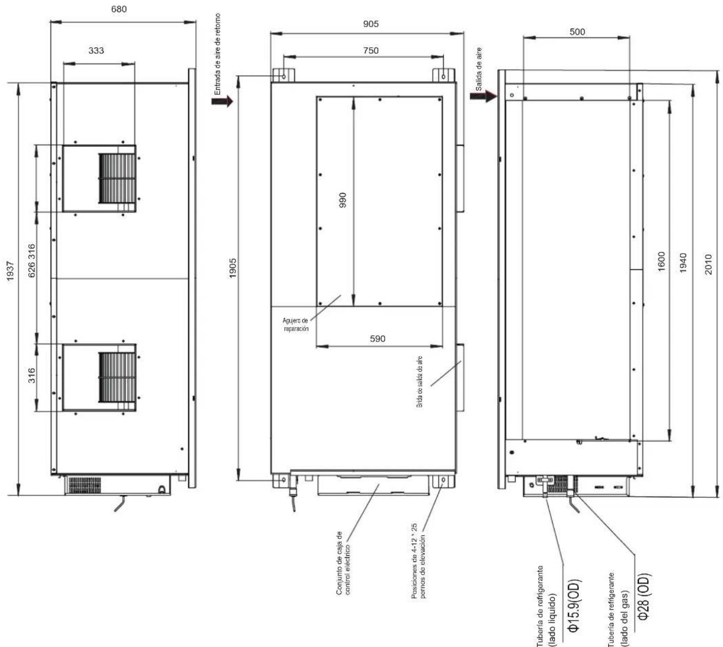
MCA: Minimum Circuit Amps
MFA: Maximum Fuse Amps
IFM: Indoor Fan Motor
kW: Rated motor output
FLA: Full Load Amps
natural_image
Simple line drawing of a woman standing next to a baby with a spiral on the phone (no text or symbols)natural_image
Line drawing of a hand holding a tool next to a spray bottle and a grid-patterned surface (no text or symbols)Figura 14.2
natural_image
Simple line drawing of a faucet spraying water onto a drain with a grid-patterned surface (no text or symbols)Figura 14.3

Precaución
- Before Installation....3
- Choosing an Installation Site ....3
- Indoor Unit Installation .... 3
- Refrigerant Piping Installation 9
- Water Discharge Piping Installation 10
- Air Duct Installation 11
- Electrical Connection 14
- On-site Configuration 16
- Test Run 17
- Part Names....19
11.The Explain Of The Display Panel....19 - Air Conditioner Operations and Performance....20
- Adjusting Air Flow Direction....20
- Maintenance 20
- Symptoms That Are Not Faults....21
- Troubleshooting 21
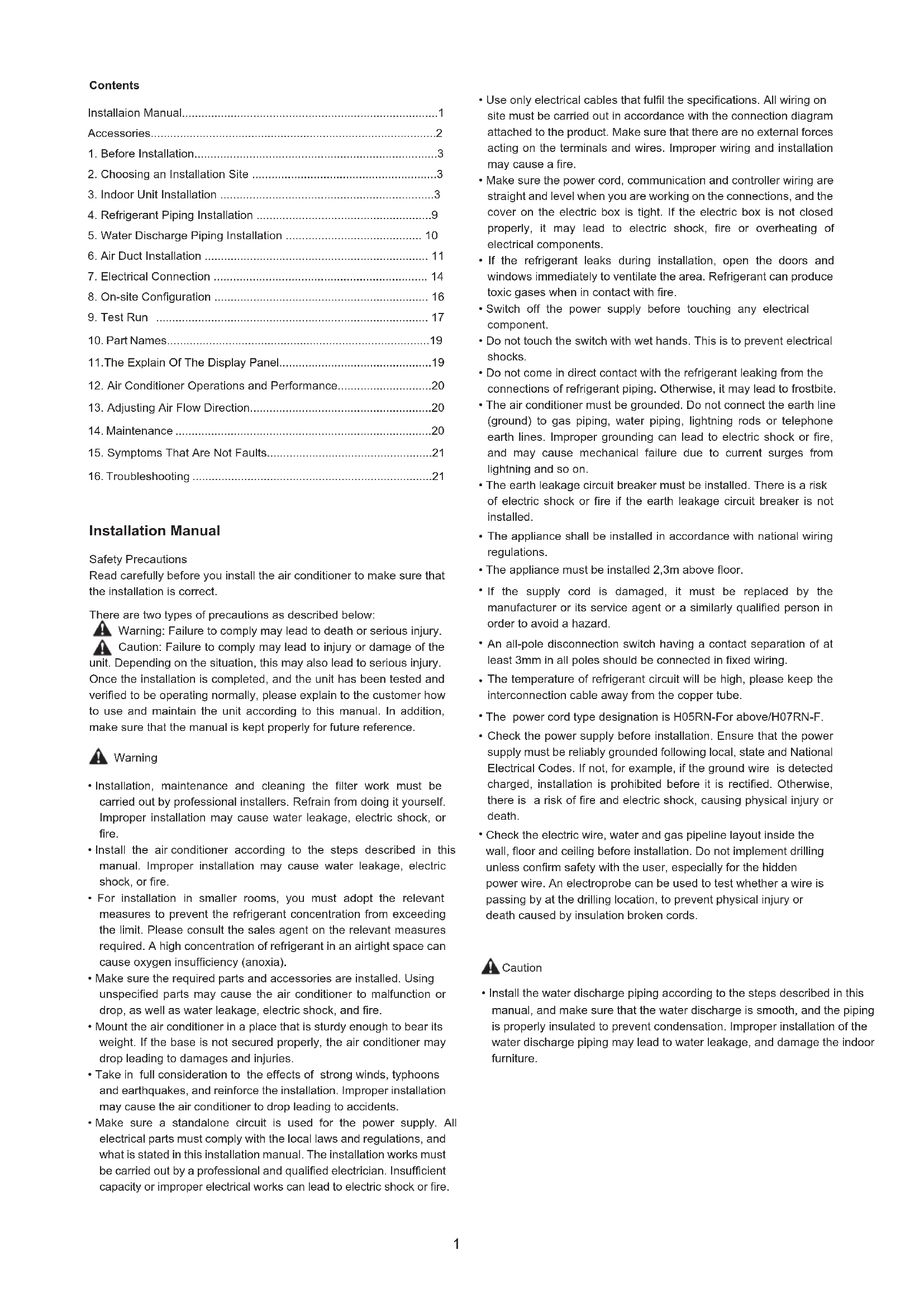
Installation Manual
Safety Precautions
Read carefully before you install the air conditioner to make sure that the installation is correct.
There are two types of precautions as described below:
Warning: Failure to comply may lead to death or serious injury. Caution: Failure to comply may lead to injury or damage of the unit. Depending on the situation, this may also lead to serious injury. Once the installation is completed, and the unit has been tested and verified to be operating normally, please explain to the customer how to use and maintain the unit according to this manual. In addition, make sure that the manual is kept properly for future reference.

Warning
- Installation, maintenance and cleaning the filter work must be carried out by professional installers. Refrain from doing it yourself. Improper installation may cause water leakage, electric shock, or fire.
- Install the air conditioner according to the steps described in this manual. Improper installation may cause water leakage, electric shock, or fire.
- For installation in smaller rooms, you must adopt the relevant measures to prevent the refrigerant concentration from exceeding the limit. Please consult the sales agent on the relevant measures required. A high concentration of refrigerant in an airtight space can cause oxygen insufficiency (anoxia).
- Make sure the required parts and accessories are installed. Using unspecified parts may cause the air conditioner to malfunction or drop, as well as water leakage, electric shock, and fire.
- Mount the air conditioner in a place that is sturdy enough to bear its weight. If the base is not secured properly, the air conditioner may drop leading to damages and injuries.
- Take in full consideration to the effects of strong winds, typhoons and earthquakes, and reinforce the installation. Improper installation may cause the air conditioner to drop leading to accidents.
-
Make sure a standalone circuit is used for the power supply. All electrical parts must comply with the local laws and regulations, and what is stated in this installation manual. The installation works must be carried out by a professional and qualified electrician. Insufficient capacity or improper electrical works can lead to electric shock or fire.
-
Use only electrical cables that fulfil the specifications. All wiring on site must be carried out in accordance with the connection diagram attached to the product. Make sure that there are no external forces acting on the terminals and wires. Improper wiring and installation may cause a fire.
- Make sure the power cord, communication and controller wiring are straight and level when you are working on the connections, and the cover on the electric box is tight. If the electric box is not closed properly, it may lead to electric shock, fire or overheating of electrical components.
- If the refrigerant leaks during installation, open the doors and windows immediately to ventilate the area. Refrigerant can produce toxic gases when in contact with fire.
- Switch off the power supply before touching any electrical component.
- Do not touch the switch with wet hands. This is to prevent electrical shocks.
- Do not come in direct contact with the refrigerant leaking from the connections of refrigerant piping. Otherwise, it may lead to frostbite.
- The air conditioner must be grounded. Do not connect the earth line (ground) to gas piping, water piping, lightning rods or telephone earth lines. Improper grounding can lead to electric shock or fire, and may cause mechanical failure due to current surges from lightning and so on.
- The earth leakage circuit breaker must be installed. There is a risk of electric shock or fire if the earth leakage circuit breaker is not installed.
- The appliance shall be installed in accordance with national wiring regulations.
- The appliance must be installed 2,3m above floor.
- If the supply cord is damaged, it must be replaced by the manufacturer or its service agent or a similarly qualified person in order to avoid a hazard.
- An all-pole disconnection switch having a contact separation of at least 3mm in all poles should be connected in fixed wiring.
- The temperature of refrigerant circuit will be high, please keep the interconnection cable away from the copper tube.
• The power cord type designation is H05RN-For above/H07RN-F. - Check the power supply before installation. Ensure that the power supply must be reliably grounded following local, state and National Electrical Codes. If not, for example, if the ground wire is detected charged, installation is prohibited before it is rectified. Otherwise, there is a risk of fire and electric shock, causing physical injury or death.
- Check the electric wire, water and gas pipeline layout inside the wall, floor and ceiling before installation. Do not implement drilling unless confirm safety with the user, especially for the hidden power wire. An electroprobe can be used to test whether a wire is passing by at the drilling location, to prevent physical injury or death caused by insulation broken cords.

Caution
• Install the water discharge piping according to the steps described in this manual, and make sure that the water discharge is smooth, and the piping is properly insulated to prevent condensation. Improper installation of the water discharge piping may lead to water leakage, and damage the indoor furniture.
- When mounting the indoor and outdoor units, make sure the power cord is installed at a distance of at least 1m away from any TV or radio so as to prevent noise or interference with the images.
- The refrigerant required for the installation is R410A. Make sure the refrigerant is correct before installation. Incorrect refrigerant may cause the unit to malfunction.
- Do not install the air conditioner in the following places:
1) Where there is oil or gas, such as the kitchen. Otherwise, the plastic parts may age, fall off or water may leak.
2) where there are corrosive gases (such as sulphur dioxide). Corrosion in the copper pipes or welded parts may cause the refrigerant to leak.
3) Where there are machines emitting electromagnetic waves. Electromagnetic waves may interfere with the control system, causing the unit to malfunction.
4) Where there is a high salt content in the air. When exposed to air with a high salt content, the mechanical parts will experience accelerated ageing which will severely compromise the service life of the unit.
5) Where there are major voltage fluctuations. Operating the unit using a power supply system that has large voltage fluctuations will reduce the service life of the electronic components, and cause the unit's controller system to malfunction.
6) Where there is a risk of leakage of flammable gases. Examples are sites that contain carbon fibres or combustible dust in the air, or where there are volatile combustibles (such as diluent or petrol). The above gases may cause explosion and fire.
7) Do not touch the fins of the heat exchanger as this may lead to injury.
8) Some products use the PP packing belt. Do not pull or tug on the PP packing belt when you transport the product. It will be dangerous if the packing belt breaks.
9) Note the recycling requirements for nails, wood, carton and other packaging materials. Do not discard these materials directly as these may lead to bodily harm.
10) Tear up the packaging bag for recycling to prevent children from playing with it, and leading to suffocation.
11) The appliance shall not be installed in the laundry.
This appliance is intended to be used by expert or trained users in shops, in light industry and on farms, or for commercial use by lay persons.
Accessories
| Code | Name of Accessories | Q'ty | Outline | Usage | |
| 1 | Installation manual | 1 | (This manual) | —— | |
| 2 | User manual | 1 |  | —— | |
| 3 | Pipe insulation material | 7.1-28.0kW | 2 |  | Heat insulation |
| 4 | Water outlet joint | 7.1-16.0kW | 1 | 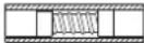 | For drainage |
| 5 | Clasp | 7.1-16.0kW | 1 |  | Check the joint that connects the drain hose and the outlet of indoor unit |
| 6 | Water connecting pipe | 20.0-28.0kW | 2 |  | To connect drain pipe |
| 40.0-56.0kW | 1 | ||||
| 7 | Adhesive tape for seal | 20.0-28.0kW | 2 | [4T50] | To connect drain pipe |
| 40.0-56.0kW | 1 | ||||
| 8 | Display | 7.1-56.0kW | 1 |  | —— |
| 9 | Weak electric cable group | 1 | [4VCO] | —— | |
| 10 | Copper nut | 1 |  | Use for connecting pipes | |
Accessories to purchase locally
| Code | Name Appearance | Dimensions | Qty | Note | |
| 1 | Copper pipe |  | Choose and purchase copper pipes that correspond to the length and size calculated for the selected model in the installation manual of the outdoor unit and your actual project requirements. | To purchase based on actual project requirements. | Use to connect indoor refrigerant piping. |
| 2 | PVC pipe for water discharge |  | Refer to specific models. | To purchase based on actual project requirements. | Use to discharge condensed water from the indoor unit. |
| 3 | Insulation casing for piping |  | The inner diameter is based on the diameter of the copper and PVC pipes. The thickness of the pipe casing is 10 mm or more. Increase the thickness of the casing (20 mm or thicker) when the temperature exceeds 30°C or the humidity exceeds RH80%. | To purchase based on actual project requirements. | Protect piping from condensation. |
| 4 | Expansion hook anchor |  | M10 | To purchase based on actual project requirements. | For installation of indoor unit. |
| 5 | Mounting hook. | 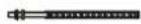 | M10 | To purchase based on actual project requirements. | For installation of indoor unit. |
| 6 | Tie | 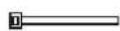 | To purchase based on actual project requirements. | To purchase based on actual project requirements. | Tie for connecting wire |
1. Before Installation
- Determine the route to move the unit to the installation site.
- First unseal and unpack the unit. Then hold the four seats of the hanger to move the unit. Refrain from exerting force on other parts of the unit, especially the refrigerant piping, water discharge piping, and plastic parts.
- The Fresh Air Processing Unit can be used either independently or in conjunction with other types of indoor unit. If used independently, the total capacity of the Fresh Air Processing Units must be between 50% and 100% of that of the outdoor units. If used in conjunction with other types of indoor unit, the total capacity of the indoor units and Fresh Air Processing Units must be between 50% and 100% of that of the outdoor units and the total capacity of the Fresh Air Processing Units must not exceed 30% of that of the outdoor units.
2. Choosing an Installation Site
2.1 Choose a site that fully complies with the following conditions and user requirements to install the air conditioning unit.
- Well ventilated.
♦ Unobstructed airflow. - Strong enough to bear the weight of the indoor unit.
- Ceiling has no obvious slant.
- There is sufficient space for repair and maintenance work to be carried out.
- No leakage of flammable gas.
- The length of the piping between the indoor and outdoor units is within the permitted range (refer to the manual on installation of the outdoor unit).
- The static pressure of the air duct of the indoor unit is within the permitted range (see 6.2 Fan Performance).

Caution
- If the indoor ambient temperature and relative humidity exceed 30^ and 80% , attach insulation materials at a thickness greater than 10 ~mm to the unit body.
2.2 Install with M10 or W3/8 lifting bolts.
2.3 The space required for installation (unit: mm) is shown in Figure 2.1 and Figure 2.2:
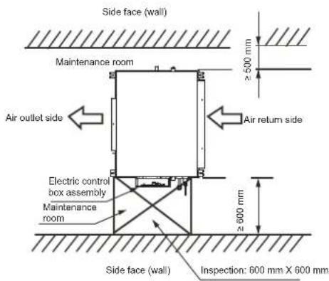
Figure 2.1
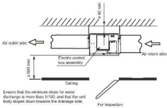
Figure 2.2
3. Indoor Unit Installation
Make sure that only specified components are used for the installation works.
3.1 Installation with Lifting Bolts
Use different bolts for the installation depending on the installation environment.
Wooden structure
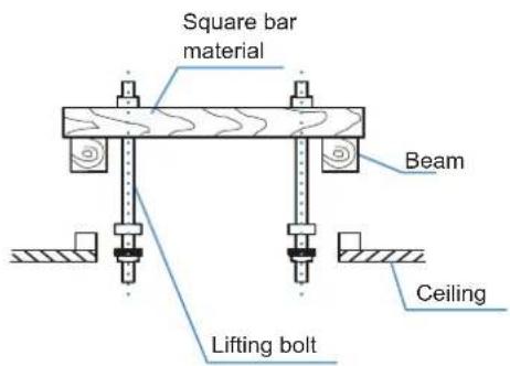
Figure 3.1
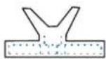
Original concrete slab structure
Use embedded bolts, and pull bolts.
natural_image
Technical line drawing of two types of electrical insulator components (no text or symbols)Figure 3.2
Steel framework
Directly set and use an angled steel rod for support.
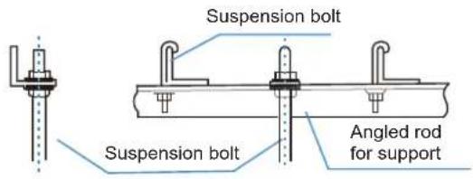
Figure 3.3
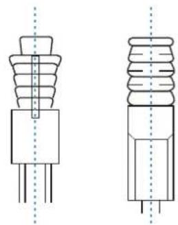
Newly set concrete slab structure
Set using embedded appliances, and embedded type of bolts.
Knife-type insertion piece
Sliding-type insertion piece
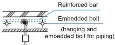
Figure 3.4

Caution
- All bolts should be made from high quality carbon steel (with galvanized surface or other rust prevention treatment) or stainless steel.
- How the ceiling should be handled will differ with the type of building. For specific measures, please consult the building and renovation engineers.
- How the lifting bolt is secured depends on the specific situation, and it must be secure and reliable.
3.2 Installation of the Indoor Unit
(1) When mounting the lifting lugs of the indoor unit on the lifting bolts, slot the nut washers of the lifting bolts in the oblong holes of the lifting lugs. The upper and lower nuts and the washers are shown in Figure 3.5.
(2) Adjust the height of the indoor unit.
(3) Use a spirit level to verify that the unit body is level (making the unit body slope downwards towards the drainage side), as shown in Figure 3.6.
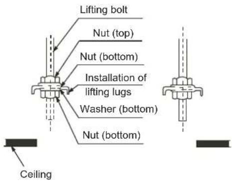
Figure 3.5
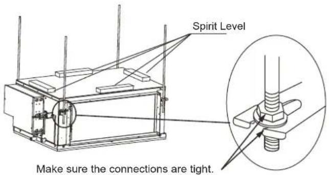
Figure 3.6
3.3 Dimensions
3.3.1 Installation dimensions of lifting bolts and location size of connecting piping (unit: mm)
Unit: mm
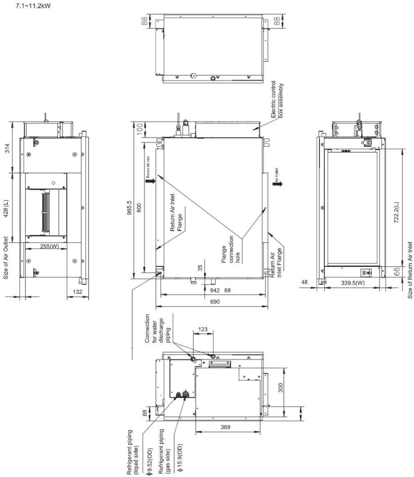
Figure 3.7
14.0\~16.0kW
Unit: mm
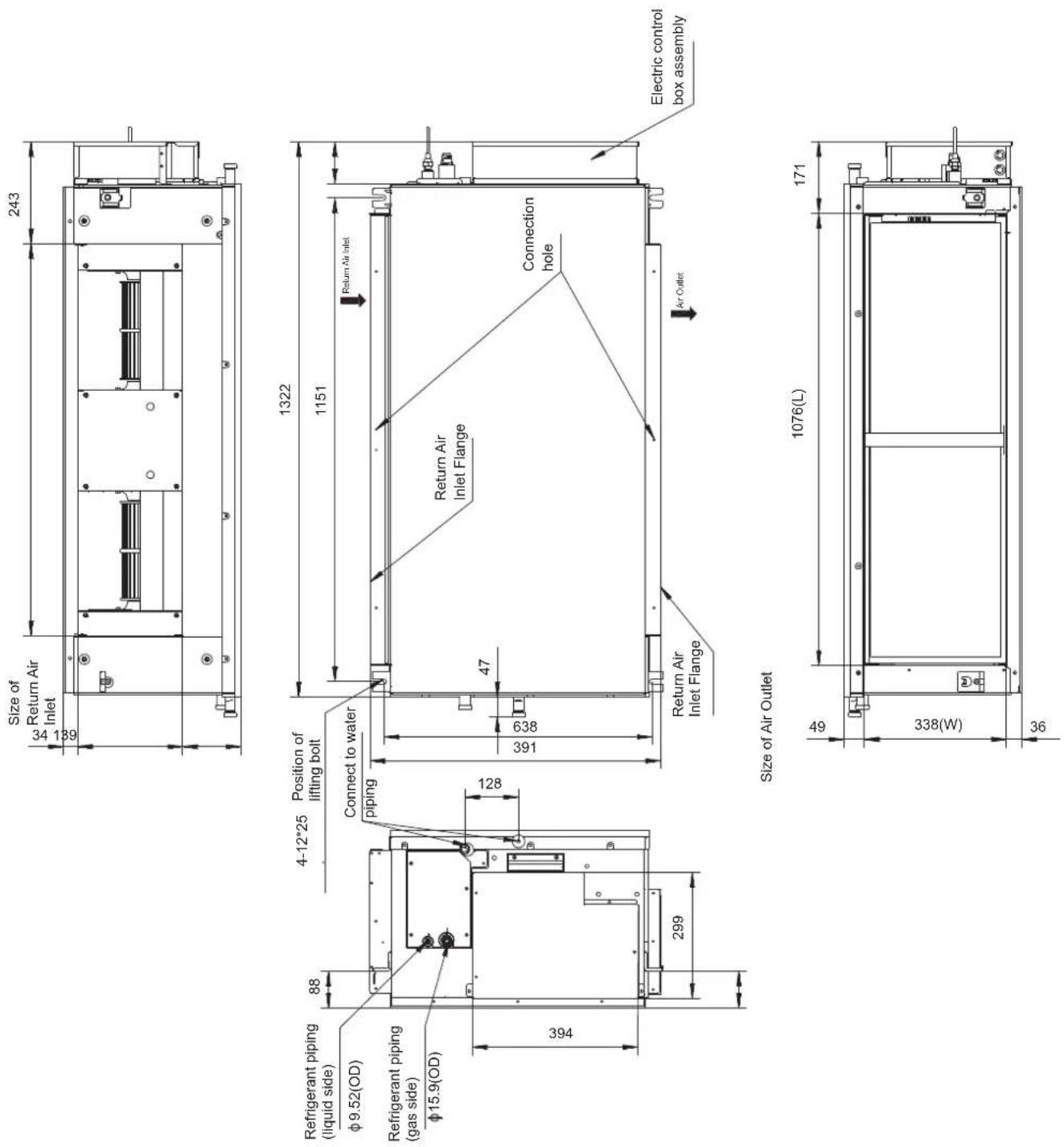
Figure 3.8
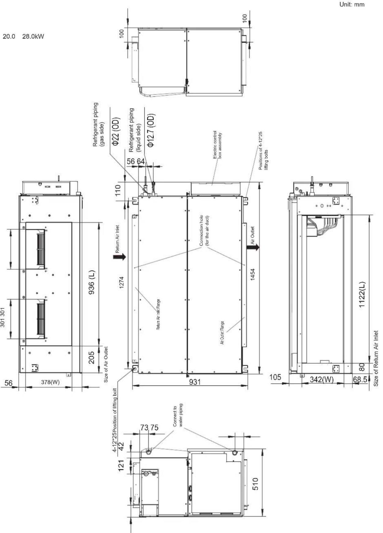
Figure 3.9
40.0\~56.0kW
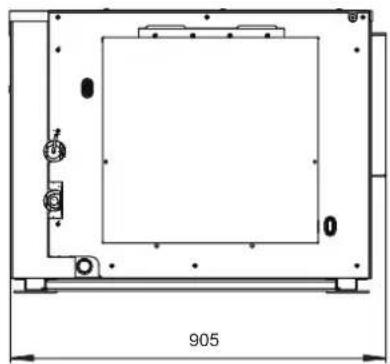
natural_image
Technical line drawing of a rectangular enclosure with internal components and dimension label (905), no readable text or symbols beyond the dimension marker.
Figure 3.10
4. Refrigerant Piping Installation
4.1 Length and Level Difference Requirements for the Piping Connections to the Indoor and Outdoor Units
The length and level difference requirements for the refrigerant piping are different for different indoor and outdoor units. Refer to the installation manual of the outdoor unit.
4.2 Piping Material and Size
-
Piping material: Copper pipes for air handling.
-
Piping size: Choose and purchase copper pipes that correspond to the length and size calculated for the selected model in the installation manual of the outdoor unit and your actual project requirements.
4.3 Piping Layout
- Seal the two ends of the piping properly before you connect the indoor and outdoor piping. Once unsealed, connect the piping of the indoor and outdoor units as quickly as possible to prevent dust or other debris from entering the piping system via the unsealed ends, as this may cause the system to malfunction.
- If the piping needs to go through walls, drill the opening in the wall, and place accessories like casings and covers for the opening properly.
- Place the refrigerant connecting piping and the communication wiring for the indoor and outdoor units together, and bundle them tightly to make sure air does not enter and condensate to form water that may leak from the system.
- Insert the bundled piping and wiring from outside the room through the wall opening into the room. Be careful when you lay out the piping. Do not damage the piping.
4.4 Piping Installation
- Refer to the installation manual attached with the outdoor unit on installation of the refrigerant piping for the outdoor unit.
All gas and liquid piping must be properly insulated; otherwise, this may cause water to leak. Use heat insulation materials that can withstand high temperatures above 120°C to insulate the gas pipes. In addition, the insulation of the refrigerant piping should be reinforced (20 mm or thicker) in situations where there is high temperature and/or high humidity (when part of refrigerant piping part is higher than 30°C or when the humidity exceeds RH80%). Otherwise, the surface of the heat insulation material may be exposed.
Before the works are carried out, verify that the refrigerant is R410A. If the wrong refrigerant is used, the unit may malfunction. - Other than the specified refrigerant, do not let air or other gases enter the refrigeration circuit.
- If the refrigerant leaks during installation, make sure you fully ventilate the room.
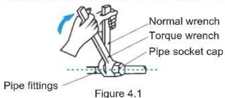
- Use two wrenches when you install or dismantle the piping, a common wrench and a torque wrench. See Figure 4.1.
- Slot the refrigerant piping into the brass nut (accessory), and expand the pipe socket. Refer to the following table for the size of the pipe socket and the appropriate tightening torque.
| External diameter (mm) | Tightening torque | Flared opening diameter (A) | Flared opening |
| Φ6.35 14.2-17 | 7.2N·m 8.3-8.7mm | 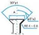 Figure 4.2 Figure 4.2 | |
| Φ9.53 32.7-39 | 9.9N·m 12-12.4mm | ||
| Φ12.7 49.5-60 | 3N·m 15.4-15.8mm | ||
| Φ15.9 61.8-75 | 4N·m 18.6-19mm | ||
| Φ19.1 97.2-11 | 6N·m 22.9-23.3mm |

Caution
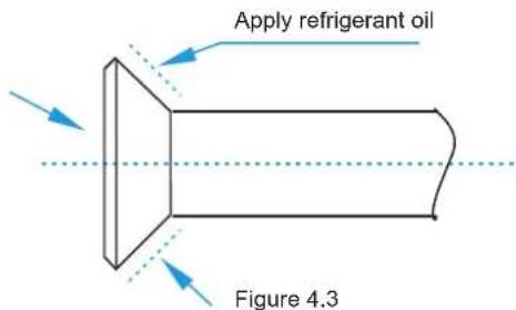
- Apply the appropriate tightening torque according to the installation conditions. Excessive torque will damage the socket cap, and the cap will not be tight if you apply insufficient torque, leading to leakages.
Before the socket cap is installed on the pipe socket, apply some refrigerant oil on the socket (both inside and outside), and then rotate it three or four times before you tighten the cap. See Figure 4.3.

Precautions to take when welding the refrigerant pipes
- Before you weld the refrigerant pipes, fill the pipes with nitrogen first to discharge the air in the pipes. If no nitrogen is filled during welding, a large amount of oxide film will form inside the piping which may cause the air conditioning system to malfunction.
- Welding can be carried out on the refrigerant pipes when the nitrogen gas has been replaced or refilled.
- When the pipe is filled with nitrogen during welding, the nitrogen must be reduced to 0.02 MPa using the pressure release valve. See Figure 4.4.
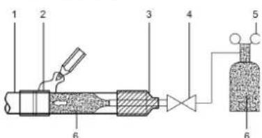
| 1 Copper piping |
| 2 Section being brazed |
| 3 Nitrogen connection |
| 4 Hand valve |
| 5 Pressure-reducing valve |
| 6 Nitrogen |
Figure 4.4
4.5 Air Tightness Test
Carry out the air tightness test on the system according to the instructions in the installation manual of the outdoor unit.

Caution
- The Air Tightness Test helps to ensure that the air and liquid cut-off valves of the outdoor unit are all closed (maintain the factory defaults).
4.6 Heat Insulation Treatment for Gas-Liquid Piping Connections for the Indoor Unit
- The heat insulation treatment is carried out on the piping at the gas and liquid sides of the indoor unit respectively.
a. The piping on the gas side must use heat insulation material that can withstand temperatures of 120^ C and more.
b. For the piping connections of the indoor unit, use the insulation casing for copper pipes (accessory) to carry out the insulation treatment, and close all gaps.
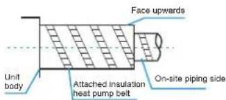
Figure 4.5
4.7 Vacuum
Create a vacuum in the system according to the instructions in the installation manual of the outdoor unit.

Caution
- For the vacuum, make sure that the air and liquid cut-off valves of the outdoor unit are all closed (maintain the factory status).
4.8 Refrigerant
Charge the system with refrigerant according to the instructions in the installation manual of the outdoor unit.
5. Water Discharge Piping Installation
5.1 Water Discharge Piping Installation for Indoor Unit
- Use PVC pipes for the water discharge pipes. Based on the installation scenario, users can purchase the appropriate piping length from a sales agent, local after-sales service center, or local market. The piping length should be at least the same length as the body of the unit.
- Insert the water discharge pipe into the end of the water suction connecting pipe of the unit body, and use the ring clamp (accessory) to clamp the water discharge pipes with the insulation casing for the water outlet piping securely.
- Use the insulation casing for water discharge piping (accessory) to bundle the water suction and discharge pipes of the indoor unit (especially the indoor portion), and use the tie for the water discharge piping (accessory) to bind them firmly to make sure air does not enter and condense.
- In order to prevent the back-flow of water into the interior of the air conditioner when the operation stops, the water discharge pipe should slope downwards towards the outside (drainage side) at a slope of more than 1/100. Make sure that the water discharge pipe does not swell or store water; otherwise, it will cause strange noises. See Figure 5.1.
- When connecting the water discharge piping, do not use force to pull the pipes to prevent the water suction pipe connections from coming loose. At the same time, set a supporting point at every 0.8\~1 m to prevent the water discharge pipes from bending. See Figure 5.1.
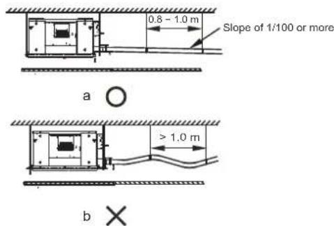
Figure 5.1
- When connecting to a long water discharge pipe, the connections must be covered with the insulation casing to prevent the long pipe from coming loose.
- Install the water discharge pipes as shown in Figure 5.2a (without a water pump) and Figure 5.2b (with a water pump). The water discharge piping outlet should not be higher than the water discharge height, ensuring a downward slope of more than 1/100.
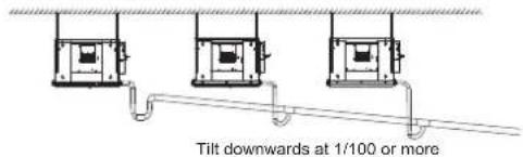
Water discharge pipes from multiple units are connected to the main water discharge pipe to be discharged through the sewage pipe.
Figure 5.2a (without a water pump)
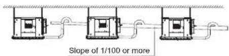
Water discharge pipes from multiple units are connected to the main water discharge pipe to be discharged through the sewage pipe.
Figure 5.2b (with a water pump)
-
The end of the water discharge pipe must be more than 50 mm above the ground or from the base of the water discharge slot. Besides, do not put it in the water.
-
Install the water storage elbow.
(1) For a water discharge duct connected to the main drain pan in the indoor unit, the water discharge piping must include a water storage elbow to prevent loading pressure from building up and causing poor water drainage, water leaks, or water being discharged out of the air outlet duct when the indoor unit is running. (2) In a scenario where the indoor unit runs continuously for long periods (48 hours or more), continuous operations, or where the relative humidity of the air is 85% or higher, connect the water discharge piping of the secondary drain pan to the main water discharge piping, and then install the water storage elbow. Install the water storage elbow as shown in Figure 5.3. Install it in such a way that it is easy to clean.
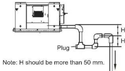
Figure 5.3 Schematic of water storage elbow

Caution
- Make sure all the connections in the piping system are properly sealed to prevent water leakages.
5.2 Water Discharge Test
Before the test, make sure that the water discharge pipeline is smooth, and check that each connection is sealed properly. Conduct the water discharge test in the new room before the ceiling is paved.
5.2.1 Indoor unit without a drainage pump
(1) Use the water injection pipe to inject about 2000 ml of water into the drain pan.
(2) Check that the water discharge piping outlet discharge water properly (based on the length of the pipe, the discharge may occur at a delay of 1 minute or so), and check for water leakages at each joint.
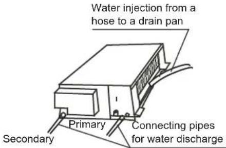
Figure 5.4 Verify water discharge
5.2.2 Indoor unit with a drainage pump
(1) Use the water injection pipe to inject about 2000 ml of water into the drain pan.
(2) Connect the power supply, and set the air conditioner to operate in the cool mode. Check the running sound of the drainage pump, as well as whether water is properly drained from the water discharge outlet.
(3) Stop the air conditioner. Wait for three minutes, and then check if there is anything unusual. If the water discharge piping layout is not correct, the excessive water flow will cause the water level error and "EE" error code will be displayed on the display panel. There may even be water overflowing from the drain pan.
(4) Continue to add water until the alarm for excessive water levels is triggered. Check if the drainage pump drains water immediately. After three minutes, if the water level does not fall below the warning level, the unit will shut down. At this time, you need to turn off the power supply, and drain away the accumulated water before you can turn on the unit normally.
(5) Turn off the power supply.
6. Air Duct Installation
6.1 Piping Design and Installation
(1) In order to prevent short-circuit air delivery, the piping for air outlet and air return ducts must not be too close.
(2) The indoor unit does not have an air filter installed. The air filter must be installed at a location like an air inlet where it can be easily maintained. (Without an air filter, dust particles may stick to the air heat exchanger which will make the air conditioner prone to failures and water leakage.)
(3) Before installing the air duct, ensure that the static pressure of the air duct is within the permitted range of the indoor unit (see section 6.2).
(4) Connect the canvas duct to the air return and air outlet ducts to prevent vibrations from the indoor unit transferring to the ceiling.
(5) Use heat insulation materials at a thickness of 25 mm or more to prevent condensation on the air duct.
(6) Connect the air duct as shown in Figure 6.1.
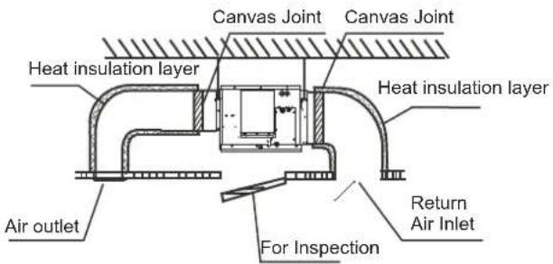
Note: On-site preparation required for all components except for the air conditioner.
Figure 6.1

Caution
- Once the air conditioner body and the canvas joints are riveted together, the upper flange plate must be secured with screws. (M6 x 12 screws are prepared on site.)
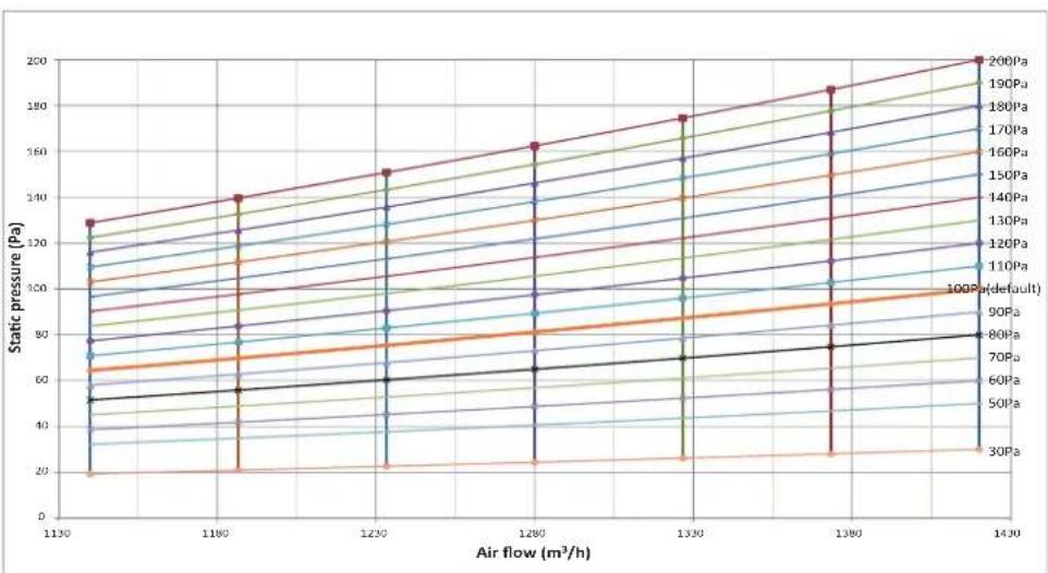
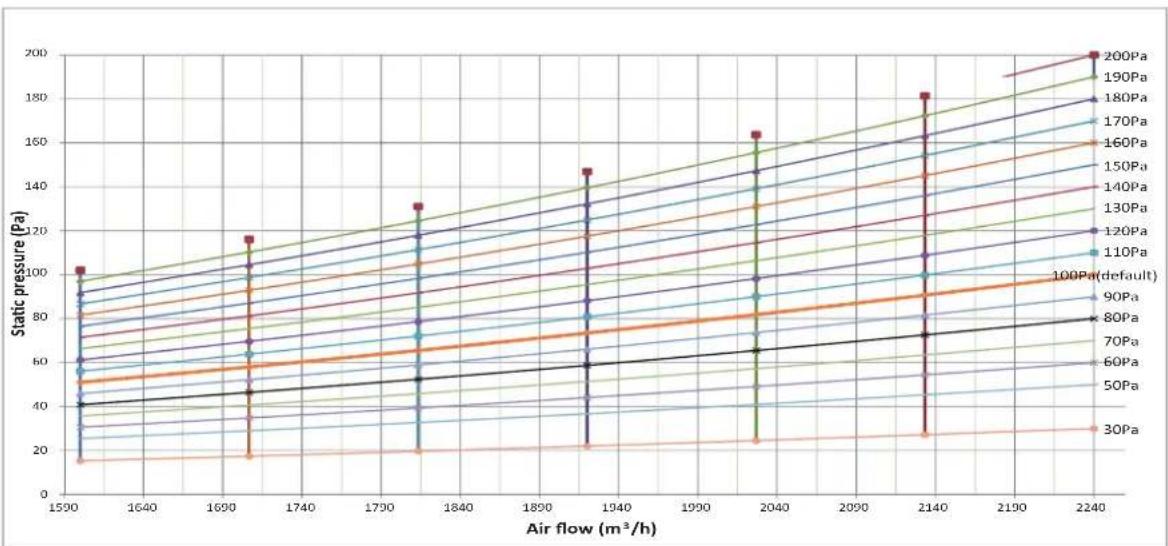
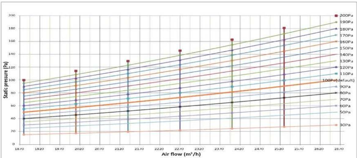
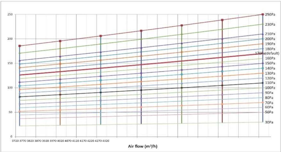
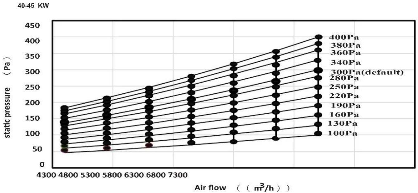
6.2 Fan Performance
7.1/8.0kW

9.0kW
line
| Air flow (m³/h) | 30Pa | 60Pa | 70Pa | 80Pa | 90Pa | 100Pa (default) | 110Pa | 120Pa | 130Pa | 140Pa | 150Pa | 160Pa | 170Pa | 180Pa | 190Pa | 200Pa | | --------------- | ---- | ---- | ---- | ---- | ---- | ---------------- | ----- | ----- | ----- | ----- | ----- | ----- | ----- | ----- | ----- | ----- | | 1130 | 20 | 40 | 60 | 80 | 100 | 120 | 140 | 160 | 180 | 200 | 220 | 240 | 260 | 280 | 300 | 320 | | 1180 | 25 | 50 | 70 | 90 | 110 | 130 | 150 | 170 | 190 | 210 | 230 | 250 | 270 | 290 | 310 | 330 | | 1230 | 30 | 60 | 80 | 100 | 120 | 140 | 160 | 180 | 200 | 220 | 240 | 260 | 280 | 300 | 320 | 340 | | 1280 | 35 | 70 | 90 | 110 | 130 | 150 | 170 | 190 | 210 | 230 | 250 | 270 | 290 | 310 | 330 | 350 | | 1330 | 40 | 80 | 100 | 120 | 140 | 160 | 180 | 200 | 220 | 240 | 260 | 280 | 300 | 320 | 340 | 360 | | 1380 | 45 | 90 | 110 | 130 | 150 | 170 | 190 | 210 | 230 | 250 | 270 | 290 | 310 | 330 | 350 | 370 | | 1430 | 50 | 100 | 120 | 140 | 160 | 180 | 200 | 220 | 240 | 260 | 280 | 300 | 320 | 340 | 360 | 380 |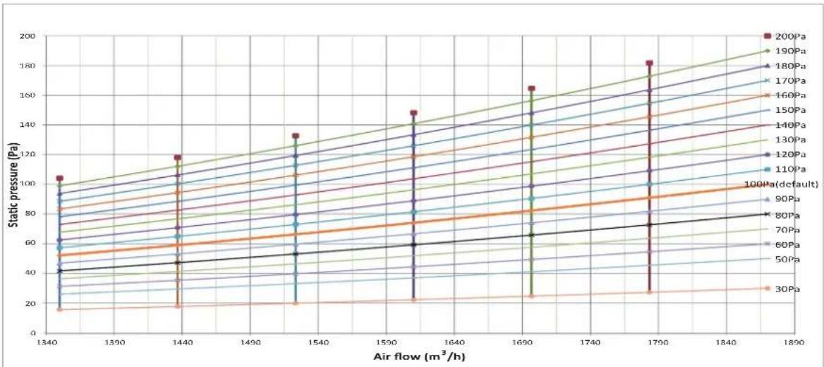
line
| Air flow (m³/h) | 200Pa | 190Pa | 180Pa | 170Pa | 160Pa | 150Pa | 140Pa | 130Pa | 120Pa | 110Pa | 100Pa(default) | | --------------- | ----- | ----- | ----- | ----- | ----- | ----- | ----- | ----- | ----- | ----- | -------------- | | 1340 | 105 | 100 | 95 | 90 | 85 | 80 | 75 | 70 | 65 | 60 | 55 | | 1440 | 115 | 110 | 105 | 100 | 95 | 90 | 85 | 80 | 75 | 70 | 65 | | 1540 | 135 | 130 | 125 | 120 | 115 | 110 | 105 | 100 | 95 | 90 | 85 | | 1690 | 165 | 160 | 155 | 150 | 145 | 140 | 135 | 130 | 125 | 120 | 115 | | 1790 | 185 | 180 | 175 | 170 | 165 | 160 | 155 | 150 | 145 | 140 | 135 | | 1890 | - | - | - | - | - | - | - | - | - | - | - |14.0kW
line
| Air flow (m³/h) | 30Pa | 50Pa | 60Pa | 70Pa | 80Pa | 90Pa | 100Pa(default) | 110Pa | 120Pa | 130Pa | 140Pa | 150Pa | 160Pa | 170Pa | 180Pa | 190Pa | 200Pa | | --------------- | ---- | ---- | ---- | ---- | ---- | ---- | -------------- | ----- | ----- | ----- | ----- | ----- | ----- | ----- | ----- | ----- | ----- | | 1590 | 15 | 25 | 35 | 45 | 55 | 65 | 75 | 85 | 95 | 105 | 115 | 125 | 135 | 145 | 155 | 165 | 175 | | 1690 | 15 | 25 | 35 | 45 | 55 | 65 | 75 | 85 | 95 | 105 | 115 | 125 | 135 | 145 | 155 | 165 | 175 | | 2240 | 30 | 45 | 60 | 75 | 90 | 105 | 120 | 135 | 150 | 165 | 180 | 195 | 210 | 225 | 240 | 260 | 280 |16.0kW
line
| Air flow (m³/h) | 100Pa | 130Pa | 160Pa | 190Pa | 220Pa | 250Pa | 280Pa | 300Pa(default) | 340Pa | 360Pa | 380Pa | 400Pa | | --------------- | ----- | ----- | ----- | ----- | ----- | ----- | ----- | -------------- | ----- | ----- | ----- | ----- | | 4300 | 50 | 50 | 50 | 50 | 50 | 50 | 50 | 50 | 50 | 50 | 50 | 50 | | 4800 | 75 | 75 | 75 | 75 | 75 | 75 | 75 | 75 | 75 | 75 | 75 | 75 | | 5300 | 100 | 100 | 100 | 100 | 100 | 100 | 100 | 100 | 100 | 100 | 100 | 100 | | 5800 | 125 | 125 | 125 | 125 | 125 | 125 | 125 | 125 | 125 | 125 | 125 | 125 | | 6300 | 150 | 150 | 150 | 150 | 150 | 150 | 150 | 150 | 150 | 150 | 150 | 150 | | 6800 | 175 | 175 | 175 | 175 | 175 | 175 | 175 | 175 | 175 | 175 | 175 | 175 | | 7300 | 200 | 200 | 200 | 200 | 200 | 200 | 200 | 200 | 200 | 200 | 200 | 200 | | >7300 | >325 | >325 | >325 | >325 | >325 | >325 | >325 | >325 | >325 | >325 | >325 | >325 | | >7300 | >400 | >400 | >400 | >400 | >400 | >400 | >400 | >400 | >400 | >400 | >400 | >400 | | >7300 | >425 | >425 | >425 | >425 | >425 | >425 | >425 | >425 | >425 | >425 | >425 | >425 | | >7300 | >450 | >450 | >450 | >450 | >450 | >450 | >450 | >450 | >450 | >450 | >450 | >450 | The chart includes a legend for each pressure level from '1' to 'P'. The y-axis is labeled 'static pressure (Pa)'. The x-axis is labeled 'Air flow (m³/h)'. Values are estimated based on the data series.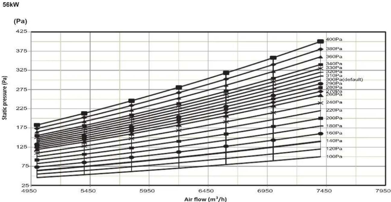
- Set proper external static pressure (ESP) according to the actual installation conditions. Otherwise it may cause some problems.
- If the connecting duct is long and the ESP setting is small, the airflow will be very small, leading to poor performance.
• If the connecting duct is short and the ESP setting is large, the airflow will be very large, leading to higher operating noise and even water may be blown out through the air outlet.
- ESP can be set through the DIP switch SW2 on the main board or the new wired controller. Please refer to Part "8.3 DIP switch settings on main board" for SW2 setting or the wired controller manual for wired controller setting.
• Four ESP can be set through DIP switch SW2.
| Capacity ESP1 ESP2 ESP3 ESP4 | ||||
| 7.1-16.0kW | 100Pa | 50Pa | 170Pa | 200Pa |
| 20.0-28.0kW | 170Pa | 100Pa | 200Pa | 250Pa |
| 45-56kW | 300Pa | 100Pa | 200Pa | 400Pa |
- Twenty ESP can be set through the new wired controller.
| Capacity | 00 01 02 | 03 04 | 05 06 07 | 08 09 | ||||||
| 7.1-16kW | 30Pa | 50Pa | 60Pa | 70Pa | 80Pa | 90Pa | 100Pa | 110Pa | 120Pa | 130Pa |
| 20-28kW | 30Pa | 50Pa | 60Pa | 70Pa | 80Pa | 90Pa | 100Pa | 110Pa | 120Pa | 130Pa |
| 40-56kW | 120Pa | 140Pa | 160Pa | 180Pa | 200Pa | 220Pa | 240Pa | 260Pa | 270Pa |
| Capacity | 10 11 12 | 13 14 | 15 16 17 | 18 19 | ||||||
| 7.1-16kW | 140Pa | 150Pa | 160Pa | 170Pa | 180Pa | 190Pa | 200Pa | 200Pa | 200Pa | 200Pa |
| 20-28kW | 140Pa | 150Pa | 160Pa | 170Pa | 180Pa | 190Pa | 200Pa | 210Pa | 230Pa | 250Pa |
| 40- 56kW | 280Pa | 290Pa | 300Pa | 310Pa | 320Pa | 330Pa | 340Pa | 360Pa | 380Pa | 400Pa |
7. Electrical Wiring

Warning
- All the supplied parts, materials and electrical works must comply with local regulations.
■ Use only copper wires. - Use a dedicated power supply for the air-conditioners. The power voltage must be in line with the rated voltage.
- The electrical wiring works must be carried out by a professional technician, and must comply with the labels stated in the circuit diagram.
Before the electrical connection works are carried out, turn off the power supply to prevent injuries caused by electric shock. - The external power supply circuit of the air conditioner must include an earth line, and the earth line of the power cord connecting to the indoor unit must be securely connected to the earth line of the external power supply.
- Leakage protective devices must be configured according to the local technical standards and requirements for electrical and electronic devices.
- The fixed wiring connected must be equipped with an all-pole disconnection device with a minimum 3 mm contact separation.
- The distance between the power cord and signalling line must be at least 300 mm to prevent the occurrences of electrical interference, malfunction or damage to electrical components. At the same time, these line must not come in contact with the piping and valves.
- Choose electrical wiring that conforms to the corresponding electrical requirements.
- Connect to the power supply only after all the wiring and connection works have been completed, and carefully checked to be correct.
7.1 Power Cord Connection
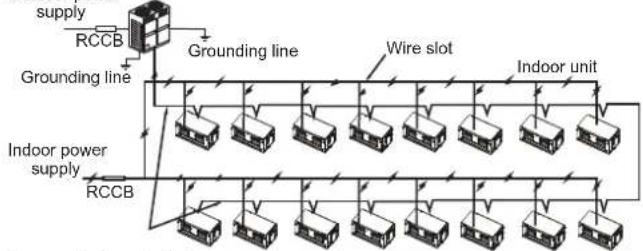
- Use a dedicated power supply for the indoor unit that is different from the power supply for the outdoor unit.
- Use the same power supply, circuit breaker and leakage protective device for the indoor units connected to the same outdoor unit.
Outdoor power
flowchart
graph TD
    A["supply"] --> B["RCCB"]
    B --> C["Grounding line"]
    C --> D["Indoor unit"]
    D --> E["Indoor power supply"]
    E --> F["RCCB"]
    F --> G["Grounding line"]
    G --> H["Indoor unit"]
    H --> I["Indoor power supply"]
    I --> J["RCCB"]
    J --> K["Grounding line"]
    K --> L["Indoor unit"]
    L --> M["Indoor power supply"]
    M --> N["RCCB"]
Communication wire between
indoor and outdoor units
Figure 7.1
Figure 7.2 shows the power supply terminal of the indoor unit.
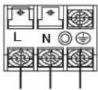
POWER INPUT
Figure 7.2
When connecting to the power supply terminal, use the circular wiring terminal with the insulation casing (see Figure 7.3).
Use power cord that conforms to the specifications and connect the power cord firmly. To prevent the cord from being pulled out by external force, make sure it is fixed securely.
If circular wiring terminal with the insulation casing cannot be used, please make sure that:
- Do not connect two power cords with different diameters to the same power supply terminal (may cause overheating of wires). See Figure 7.4.
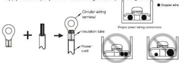
Figure 7.3
Figure 7.4
7.2 Electrical Wiring Specifications
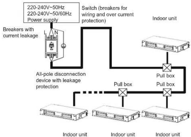
flowchart
graph TD
    A["Indoor unit"] --> B["Pull box"]
    B --> C["All-pole disconnection device with leakage protection"]
    C --> D["Breakers with current leakage"]
    D --> E["Switch (breakers for wiring and over current protection)"]
    E --> F["Indoor unit"]
    F --> G["Pull box"]
    G --> H["All-pole disconnection device with leakage protection"]
    H --> I["Breakers with current leakage"]
    I --> J["220-240V~50Hz 220-240V~50/60Hz Power supply"]
    J --> K["Indoor unit"]
Figure 7.5
Refer to Tables 7.1 and 7.2 for the specifications of the power cord and communication wire. A wiring capacity that is too small will cause the electrical wiring to become too hot, and lead to accidents when the unit burns and becomes damaged.
Table 7.1
| Model | 7.1-56.0kW | |
| Power supply | Phase | 1-phase |
| Volt and frequency | 220-240V~50Hz220-240V~50/60Hz | |
| Communication wire between indoor and outdoor units | Shield 3×AWG16-AWG20 | |
| Communication wire between indoor unit and wired controller * | Shield AWG16-AWG20 | |
| Field fuses(7.1-28kW/45-56kW) | 15A/30A | |
* Please refer to the corresponding wired controller manual for the wired controller wiring.
Table 7.2 Indoor units electrical characteristics
| Model name | Power supply | IFM | ||||
| Hz Volts | MCA MFA | kW FLA | ||||
| 7.1kW | 50/60 | 220-240 | 15 0.1 | 52.1 | 1.7 | |
| 8.0kW | 15 0.1 | 52.1 | 1.7 | |||
| 9.0kW | 15 0.1 | 82.2 | 1.7 | |||
| 11.2kW | 15 0.3 | 12.9 | 2.3 | |||
| 14.0kW | 15 0.3 | 44.5 | 3.6 | |||
| 16.0kW | 15 0.5 | 64.7 | 3.8 | |||
| 20.0kW | 15 0.8 | 6.7 | 5.4 | |||
| 25.0kW | 15 0.9 | 26.7 | 5.4 | |||
| 28.0kW | 15 | 0.926.7 | 5.4 | |||
| 40.0-50.0kW | 30 | 1.84 12 | 412.5 | |||
| 56.0kW | 30 | 1.84 12 | 415.4 | |||
Abbreviations:
MCA: Minimum Circuit Amps MFA: Maximum Fuse Amps
IFM: Indoor Fan Motor kW: Rated motor output
FLA: Full Load Amps
- Select the wire diameters (minimum value) individually for each unit based on the Table 7.3, where the rated current in Table 7.3 means MCA in Table 7.2.
- Maximum allowable voltage range variation between phases is 2%.
- Select circuit breaker that having a contact separation in all poles not less than 3 mm providing full disconnection, where MFA is used to select the current circuit breakers and residual current operation breakers:
Table 7.3
| Rated current of appliance (A) | Nominal cross-sectional area ( mm^2 ) | |||||
| Flexible cords | Cable for fixed wiring | |||||
| ≤3 | 0.5 | and 0.75 | 1 | to | 2.5 | |
| >3 and ≤6 | 0.75 | and | 1 | 1 | to | 2.5 |
| >6 and ≤10 | 1 | and | 1.5 | 1 | to | 2.5 |
| >10 and ≤16 | 1.5 | and | 2.5 | 1.5 | to | 4 |
| >16 and ≤25 | 2.5 | and | 4 | 2.5 | to | 6 |
| >25 and ≤32 | 4 | and | 6 | 4 | to | 10 |
| >32 and ≤50 | 6 | and | 10 | 6 | to | 16 |
| >50 and ≤63 | 10 | and | 16 | 10 | to | 25 |

Warning
Refer to local laws and regulations when deciding on the dimensions for the power cords and wiring. Get a professional to select and install the wiring.
7.3 Communication Wiring
Use only shielded wires for the communication wiring. Any other type of wires may produce a signal interference that will cause the units to malfunction.
Do not carry out electrical works like welding with the power on.
Do not bind the refrigerant piping, power cords and communication wiring together. When the power cord and communication wiring are parallel, the distance between the two lines must be 300 mm or more in order to prevent signal source interference.
- Communication wiring must not form a closed loop.
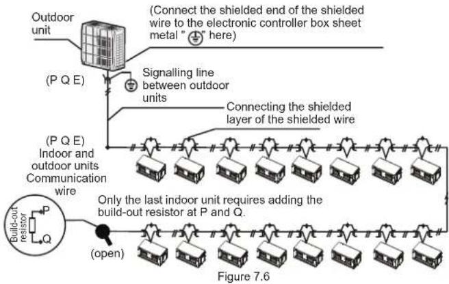
7.3.1 Communication wiring between the indoor and outdoor units
- The indoor and outdoor units communicate via the RS485 serial port.
- The communication wiring between the indoor and outdoor units should connect one unit after another in a daisy chain from the outdoor unit to the final indoor unit, and the shielded layer must be properly grounded, and a build-out resistor must be added to the last indoor unit to enhance the stability of the communication system (see Figure 7.6).
- Incorrect wiring such as a star connection or a closed ring will cause instability of the communication system and system control anomalies.
- Use a three core shielded wire (greater than or equal to 0.75 mm ^2 ) for the communication wiring between the indoor and outdoor units. Make sure the wiring is connected correctly. The connecting lead for this communication wire must come from the master outdoor unit.
- All shielded wiring in the network are interconnected, and will eventually connect to earth at the same point “ ⊕ ”.
7.3.2 Communication wiring between the indoor unit and wired controller The wired controller and the indoor unit can be connected in different manners, depending on the forms of communication.
1) For a bidirectional communication mode:
Use 1 wired controller to control 1 indoor unit or 2 wired controllers (one master and one slave controller) to control 1 indoor unit (see Figure 7.7);
Use 1 wired controller to control multiple indoor units or 2 wired controllers (one master and one slave controller) to control multiple indoor units (see Figure 7.8);
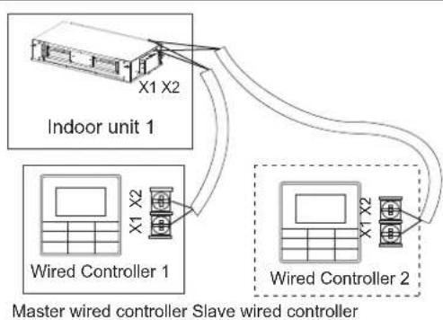
flowchart
graph TD
    A["Indoor unit 1"] -->|X1 X2| B["Wired Controller 1"]
    A -->|X1 X2| C["Wired Controller 2"]
    B --> D["Master wired controller Slave wired controller"]
    C --> D
Figure 7.7
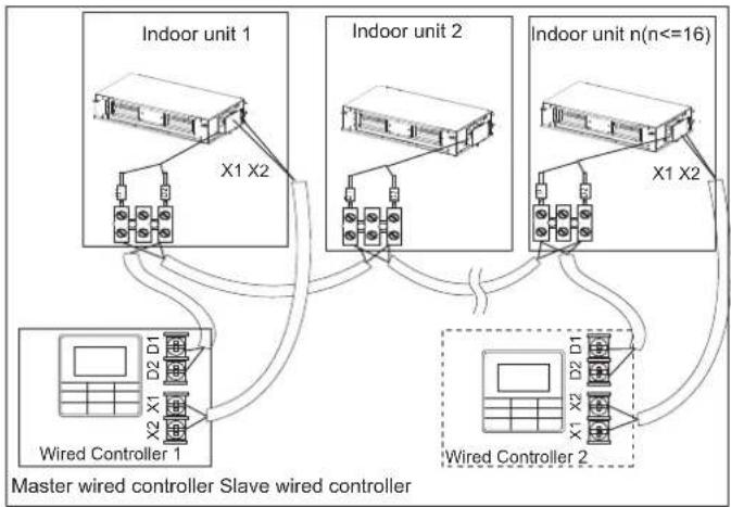
flowchart
graph TD
    subgraph Indoor unit 1
        A["Indoor unit 1"] --> B["X1 X2"]
        C["Indoor unit 2"] --> D["X1 X2"]
        E["Indoor unit n(n<=16)"] --> F["X1 X2"]
    end
    G["Wired Controller 1"] --> H["X2 X1 D2 D1"]
    I["Wired Controller 2"] --> J["X1 X2 D2 D1"]
    K["Master wired controller Slave wired controller"] --> L["Output"]
    style A fill:#f9f,stroke:#333
    style C fill:#f9f,stroke:#333
    style E fill:#f9f,stroke:#333
    style F fill:#f9f,stroke:#333
    style G fill:#ccf,stroke:#333
    style I fill:#ccf,stroke:#333
    style K fill:#ccf,stroke:#333
Figure 7.8
2) For a unidirectional communication mode:
Use 1 wired controller to control 1 indoor unit (see Figure 7.9).
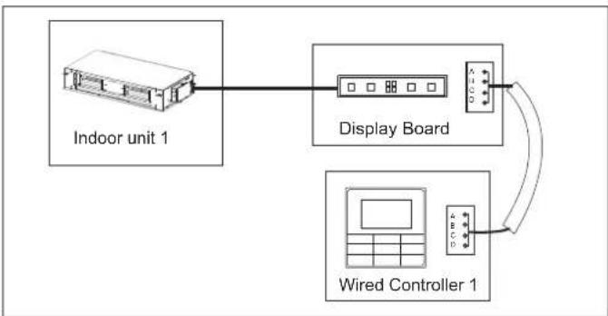
flowchart
graph TD
    A["Indoor unit 1"] --> B["Display Board"]
    B --> C["Wired Controller 1"]
    C --> B
Figure 7.9
The X1, X2, D1, D2 ports on the sides of the main control board and the unidirectional communication port (display board side) are for different types of wired controllers (see Figure 7.10).
Use the connecting wires (accessory 8) to connect the D1, D2 ports.
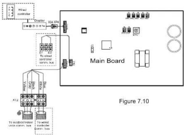

Caution
- For the specific connection method, refer to the instructions in the corresponding wired controller manual to carry out the wiring and connections.
7.4 Handling the Electrical Wiring Connection Points
Once the wiring and connections are done, use tie straps to secure the wiring properly so that the connection joint cannot be pulled apart by external force. The connection wiring must be straight out so that the cover of the electrical box is level and can be closed tightly.
- Use professional insulation and sealing materials to seal and protect the perforated wires. Poor sealing may lead to condensation, and entry of small animals and insects that may cause short circuits in parts of the electrical system, causing the system to fail.
8. On-site Configuration
8.1 Capacity Settings
Set up the PCB DIP switch on the indoor electric control box to cater to different uses. Once the settings are done, make sure you cut off the main power switch again, and then switch the power on. If the power is not cut off and switched on again, the settings will not be executed.

SW7
ENC1 Settings for Capacity DIP Switch:
| ENC1 + SW7 | ENC1 + SW7 | ||||
| Toggle switch | Set cooling capacity | Toggle switch | Set cooling capacity | Toggle switch | Set cooling capacity |
| Dial code | Cooling capacity | Dial code | Cooling capacity | Dial code | Cooling capacity |
| 0 | 2200W* | 10000W 8 | 0 | 28000W | |
| 1 | 2800W* | 9 | 11200W | 1 | 33500W* |
| 2 | 3600W* | 12500WA | 2 | 40000W | |
| 3 | 4500W* | 14000WB | 3 | 45000W | |
| 4 | 5600W* | 16000WC | 4 | 56000W | |
| 5 | 7100W | 18000WD | |||
| 6 | 8000W | 20000WE | |||
| 7 | 9000W | 25000WF | |||
* Reserved

Caution
- The capacity DIP switches have been configured before delivery. Only a professional maintenance personnel should change these settings.
8.2 Address Settings
When this indoor unit is connected to the outdoor unit, the outdoor unit will automatically allocate the address to the indoor unit. Alternatively, you may use the controller to manually set the address.
- The addresses of any two indoor units in the same system cannot be the same.
- The network address and the indoor unit address are the same, and does not have to be configured separately.
- Once the address settings are completed, mark the address of each indoor unit to facilitate after-sales maintenance.
- The centralized control of the indoor unit is completed on the outdoor unit. For details, refer to the manual on the outdoor unit.

Caution
- Once the centralized control function for the indoor unit has been completed on the outdoor unit, the DIP switch on main control panel of the outdoor unit must be set to auto addressing; otherwise, the indoor unit in the system are not controlled by the centralized controller.
- The system can connect up to 64 indoor units (address 0\~63) at the same time. Each indoor unit can only have one address DIP switch in the system. The addresses of any two indoor units in the same system cannot be the same. Units that have the same address may malfunction.
8.3 DIP Switch Settings on Main Board
| SW1_1 | |
| SW1[0] | Cooling mode temperature compensation is 0°C |
| SW1[1] | Cooling mode temperature compensation is 2°C |
| SW1_2 | |
| SW1[0] | EEV at position 96 (steps) in standby in heating mode |
| SW1[1] | EEV at position 72 (steps) in standby in heating mode |
| SW2 | |
| SW2[00] | External static pressure 1 |
| SW2[01] | External static pressure 2 |
| SW2[10] | External static pressure 3 |
| SW2[11] | External static pressure 4 |
Note:
| Capacity ESP1 ESP2 ESP3 ESP4 | ||||
| 7.1-16.0kW | 100Pa | 50Pa | 170Pa | 200Pa |
| 20.0-28.0kW | 170Pa | 100Pa | 200Pa | 250Pa |
| 40.0-56.0kW | 300Pa | 100Pa | 200Pa | 400Pa |
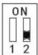
| SW3_1 | |
| SW3[0]ON1 2 | Reserved |
| SW3[1]ON1 2 | Clear indoor unit address |
| SW3_2 | |
| SW3[0]ON1 2 | Reserved |
| SW4 | |
| SW4[00]ON1 2 | In heating mode when the set temperature has been reached, the fan operates in a 4 minutes off / 1 minute on repeating cycle |
| SW4[01]ON1 2 | In heating mode when the set temperature has been reached, the fan operates in an 8 minutes off / 1 minute on repeating cycle |
| SW4[10]ON1 2 | In heating mode when the set temperature has been reached, the fan operates in a 12 minutes off / 1 minute on repeating cycle |
| SW4[11]ON1 2 | In heating mode when the set temperature has been reached, the fan keep running at low fan speed |
| SW5 | |
| SW5[00]ON1 2 | In heating mode fan does not run when indoor heat exchanger mid-point temperature is 15^ or below |
| SW5[01]ON1 2 | In heating mode fan does not run when indoor heat exchanger mid-point temperature is 20^ or below |
| SW5[10]ON1 2 | In heating mode fan does not run when indoor heat exchanger mid-point temperature is 24^ or below |
| SW5[11]ON1 2 | In heating mode fan does not run when indoor heat exchanger mid-point temperature is 26^ or below |
| SW6 | |
| SW6[00]ON1 2 | Heating mode temperature compensation is 6^ |
| SW6[01]ON1 2 | Heating mode temperature compensation is 2^ |
| SW6[10]ON1 2 | Heating mode temperature compensation is 4^ |
| SW6[11]ON1 2 | Heating mode temperature compensation is 0^ (use follow me function) |
| SW7_1 | |
| SW7[0] | Reserved |
| SW7_2 | |
| SW7[0]ON1 2 | Unit with capacity less than 28kW |
| SW7[1]ON1 2 | Unit with capacity equal or more than 28kW |
| J1 | |
| Auto restart function enabled | |
| Auto restart function disabled | |
| 0/1 definition of each dial code switch: | |
| [IMAGE] means 0 | [IMAGE] means 1 |

Note
- All DIP switches (including the capacity DIP switch) have been configured before delivery. Only a professional maintenance personnel should change these settings.
- Improper DIP switch settings may cause condensation, noise, or unexpected system malfunction.
. The default DIP switch setting is based on the actual unit.
8.4 Error Codes and Definitions
| Error code | Content |
| E0 Mode conflict | |
| E1 | Communication error between indoor and outdoor units |
| E2 | Indoor ambient temperature sensor (T1) error |
| E3 | Indoor heat exchanger mid-point temperature sensor (T2) error |
| E4 | Indoor heat exchanger outlet temperature sensor (T2B) error |
| E6 | Fan error |
| E7 | EEPROM error |
| Eb | Indoor EEV coil error |
| Ed | Outdoor unit error |
| EE Water level error | |
| FE | Indoor unit has not been assigned an address |
9. Test Run
9.1 Things to Note Before Test Run
1) Indoor and outdoor units are properly installed;
2) Piping and wiring are correct;
3) No leakage from the refrigerant piping system;
4) Water discharge is smooth;
5) Insulation is complete;
6) Grounding line has been properly connected;
7) Piping length, and amount of refrigerant filled have been recorded;
8) The voltage of the power supply is the same as the rated voltage of the air conditioner;
9) No obstacles at the air inlet and outlet of the indoor and outdoor units;
10) Cut-off valves for the gas and liquid ends are opened;
11) Connect to the power supply to let the air conditioner warm up first.
9.2 Test Run
Use wired/remote controller to control and operate the air conditioner in the cooling mode. Check the following items according to the manual. If there is any fault, troubleshoot by referring to the section "Air Conditioner Errors and Causes" in the manual.
9.2.1 Indoor unit
1) Wired/remote controller switch is operating normally;
2) Function keys of the wired/remote controller are operating normally;
3) Room temperature regulation is normal;
4) LED indicator is on;
5) Key for manual operation is normal;
6) Water discharge is normal;
7) No vibration and strange sounds during operation;
9.2.2 Outdoor unit
1) No vibration and strange sounds during operation;
2) If the wind, noise and condensation affect the neighbours;
3) Any refrigerant leakage.

Note
Once the power is connected, when the unit is turned on or started immediately after the unit is turned off, the air conditioner has a protective function which delays the start of the compressor by 3 minutes.
Operation Manual
There are two types of precautions as described below:
Warning: Failure to comply may lead to death or serious injury. Caution: Failure to comply may lead to injury or damage of the
unit. Depending on the situation, this may also lead to serious injury. Once the installation is completed, please keep the manual properly for future reference. When this air conditioner is handed over to other users, make sure that the manual is included with the handover.

Warning
- Do not use this unit in locations where flammable gas may exist. If flammable gas comes into contact with the unit, a fire may occur, which could result in serious injury or death.
- If this unit exhibits any abnormal behavior (such as emitting smoke) there is a danger of serious injury. Disconnect the power supply and contact your supplier or service engineer immediately.
- The refrigerant in this unit is safe and should not leak if the system is designed and installed properly. However, if a large amount of refrigerant leaks into a room, the oxygen concentration will decrease rapidly, which can cause serious injury or death. The refrigerant used in this unit is heavier than air, so the danger is greater in basements or other underground spaces. In the event of a refrigerant leak, turn off any devices that produce a naked flame and any heating devices, ventilate the room, and contact your supplier or service engineer immediately.
- Toxic fumes may be produced if the refrigerant in this unit comes into contact with naked flames (such as from a heater, gas stove/burners, or electric appliances).
- If this unit is used in the same room as a cooker, stove, hob, or burner, ventilation for sufficient fresh air must be ensured, otherwise the oxygen concentration will fall, which may cause injury.
- Dispose of this unit's packaging carefully, so children cannot play with it. Packaging, especially plastic packaging, can be dangerous, can cause serious injury or death. Screws, staples and other metal packaging components can be sharp and should be disposed of carefully to avoid injury.
- Do not attempt to inspect or repair this unit yourself. This unit should only be serviced and maintained by a professional air conditioning service engineer. Incorrect servicing or maintenance can cause electric shocks, fire or water leaks.
- This unit should only be re-positioned or re-installed by a professional technician. Incorrect installation can lead to electric shocks, fire or water leaks. The installation and grounding of electrical appliances should only be carried out by licensed professionals. Ask your supplier or installation engineer for further information.
- Do not allow this unit or its remote controller to come into contact with water, as this can lead to electric shocks or fire.
- Turn off the unit before cleaning it to avoid electric shocks. Otherwise, an electric shock and injury may result.
- To avoid electric shocks and fires, install an earth leakage detector.
- Do not use paint, varnish, hair spray, other flammable sprays or other liquids that may give off flammable fumes/vapor near this unit, as doing so can cause fires.
- When replacing a fuse, ensure that the new fuse to be installed completely complies with requirements.
- Do not open or remove the unit's panel when the unit is powered on. Touching the unit's internal components while the unit is powered on can lead to electric shocks or injuries caused by moving parts such as the unit's fan.
- Ensure that the power supply is disconnected before any servicing or maintenance is carried out.
- Do not touch the unit or its remote controller with wet hands, as doing so can lead to electric shocks.
- Do not allow children to play near this unit, as doing so risks injury.
- Do not insert your fingers or other objects into the unit's air inlet or air outlet to avoid injury or damage to the equipment.
- Do not spray any liquids onto the unit or allow any liquids to drip onto the unit.
- Do not place vases or other liquid containers on the unit or in places where liquid could drip onto it. Water or other liquids that come into contact with the unit can lead to electric shocks or fires.
- Do not remove the remote controller's front or back overs and do not touch the remote controller's internal components, as doing so can cause injury. If the remote controller stops working, contact your supplier or service engineer.
- Ensure that the unit is properly grounded, otherwise electric shocks or a fire may result. Electrical surges (such as those that can be caused by lightning) can damage electrical equipment. Ensure that suitable surge protectors and circuit breakers are properly installed, otherwise electric shocks or a fire may result.
- Dispose of this unit properly and in accordance with regulations. If electrical appliances are disposed of in landfills or dumps, hazardous substances can leak into the groundwater and thus enter the food chain.
- Do not use the unit until the qualified technician instructs you that it is safe to do so.
- Do not place appliances that produce naked flames in the path of the airflow from the unit. The airflow from the unit may increase the rate of combustion, which may cause a fire and cause serious injury or death. Alternatively, the airflow may cause incomplete combustion which can lead to reduced oxygen concentration in the room, which can cause serious injury or death.

Caution
- Only use the air conditioner for its intended purpose. This unit should not be used to provide refrigeration or cooling for food, plants, animals, machinery, equipment or art.
- Do not insert your fingers or other objects into the unit's air inlet or air outlet to avoid injury or damage to the equipment.
- The fins on the unit's heat exchanger are sharp and can cause injury if touched. To prevent injury, when the unit is being serviced, gloves should be worn or the heat exchanger should be covered.
- Do not place items which might be damaged by moisture under the unit. When the humidity is greater than 80% or if the drain pipe is blocked or the air filter is dirty, water could drip from the unit and damage objects placed under the unit.
- Ensure that the drain pipe functions properly. If the drain pipe is blocked by dirt or dust, water leaks may occur when the unit is running in cooling mode. If this happens, turn the unit off and contact your supplier or service engineer.
- Do not touch the internal parts of the controller. Do not remove the front panel. Some internal parts may cause injury or be damaged.
- Ensure that children, plants and animals are not directly exposed to the airflow from the unit.
- When fumigating a room with insecticide or other chemicals, cover the unit well and do not run it. Failure to observe this caution could lead to chemicals getting deposited inside the unit and later emitted from the unit when it running, endangering the health of any room occupants.
- Do not dispose of this product as unsorted waste. It must be separately collected and processed. Ensure that all applicable legislation regarding the disposal of refrigerant, oil and other materials is adhered to. Contact your local waste disposal authority for information about disposal procedures.
- To avoid damaging the remote controller, exercise caution when using it and replacing its batteries. Do not place objects on top of it.
- Do not place appliances that have naked flames under or near the unit, as heat from the appliance can damage the unit.
- Do not place the unit's remote controller in direct sunlight. Direct sunlight can damage the remote controller's display.
- Do not use strong chemical cleaners to clean the unit, as doing so can damage the unit's display or other surfaces. If the unit is dirty or dusty, use a slightly damp cloth with very diluted and mild detergent to wipe the unit. Then, dry it with a dry cloth.
• Children shall not play with the appliance.
- Do not dispose of this product as unsorted waste. It must be separately collected and processed. Ensure that all applicable legislation regarding the disposal of refrigerant, oil and other materials is adhered to. Contact your local waste disposal authority for information about disposal procedures.
- This appliance is not intended for use by persons (including children) with reduced physical, sensory or mental capabilities, or lack of experience and knowledge, unless they have been given supervision or instruction concerning use of the appliance by a person responsible for their safety. Children should be supervised to ensure that they do not play with the appliance.
- This appliance can be used by children aged from 8 years and above and persons with reduced physical, sensory or mental capabilities or lack of experience and knowledge if they have been given supervision or instruction concerning use of the appliance in a safe way and understand the hazards involved. Children shall not play with the appliance. Cleaning and user maintenance shall not be made by children without supervision.
10. Part Names
The figure shown above is for reference only and may be slightly different from the actual product.
Air Outlet Louver (adjustable)
For in-situ adjustment to three-direction or two-direction, please contact the local dealer.
■ High static pressure duct type
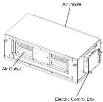
Figure 10.1
11. The Explain Of The Display Panel
The display panel has one type and the appearance of the type is shown in Figure 11.1.
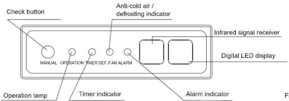
Figure 11.1
Table: Display panel output under normal operating conditions.
| Unit state | Display output | ||
| Digital display panels | |||
| Unit state Digital display | |||
| Standby | Operation indicator flashes slowly |  | |
| Shutting-down | All indicators off |  | |
| Operation | Normal operation | Operation indicator on | Cooling and heating modes: set temperatureFan only mode: indoor ambient temperature |
| Cold draft prevention or outdoor unit defrosting operation | Operation and Anti-cold / defrosting indicators on | Set temperature | |
| A timer has been set Timer indicator | on | ||
12. Air Conditioner Operations and Performance
The operating temperature range under which the unit runs stably are given in below table.
| Cooling mode | Heating mode | |
| 17~32°C(DB) 15~27 °C(DB)Indo | ||
| Indoor humidity | ≤80% (a) | |
| (a) Condensation will form on the unit surface and water dripping out of the unit when the indoor humidity is beyond 80% | ||

Caution
- The unit performs stably in the temperature range given in above table. If the indoor temperature is outside the unit's normal operating range, it may stop running and display an error code.
To ensure the desired temperature is achieved efficiently, ensure that:
• All windows and door are closed.
• The airflow direction is adjusted to work in running mode.
• The air filter is clean.
Please note how you can best save energy and achieve the best cooling/heating effect.
◆ Regularly clean air filters inside indoor units.
- Avoid too much outdoor air coming into air-conditioned spaces.
Note that outlet air is cooler or heater than set room temperature. Avoid direct exposure to outlet air as it may be too cool or hot.
- Maintain a proper air distribution. Air outlet louvers should be used to adjust the direction of outlet airflow, as doing so might ensure more efficient operation.
natural_image
Simple line drawing of a woman standing beside a baby with a spiral on top (no text or symbols)13. Adjusting Air Flow Direction
Since warmer air rises and cooler air falls, the distribution of warmed/cooled air around a room can be improved by positioning the unit's louvers. The louver angle can be adjusted by pressing the [SWING] button on the remote controller.
or temperature

Caution
- During heating operation, horizontal airflow will aggravate the uneven distribution of room temperature.
- The louver direction: horizontal airflow is recommended during cooling operation. Note the downward air flow will cause condensation on the air outlet and louver surface.
14. Maintenance

Caution
- Please release pressure before disassembly.
- Before you clean the air conditioner, ensure it is powered off.
- Check that the wiring is undamaged and connected.
- Use a dry cloth to wipe the indoor unit and remote controller.
- A wet cloth may be used to clean the indoor unit if it is very dirty.
- Never use a damp cloth on the remote controller.
- Do not use a chemically treated duster on the unit or leave this type of material on the unit to avoid damaging the finish.
- Do not use benzene, thinner, polishing powder, or similar solvents for cleaning. These may cause the plastic surface to crack or warp.
◆ Method for cleaning the air filter
a. The air filter can prevent the dust or other particles from entering the unit. If the filter is blocked, the unit will not work well. Clean the filter every two weeks when you use it regularly.
b. If the air conditioner is positioned in a dusty place, clean the filter often.
c. Replace the filter if it is too dusty to clean (the replaceable air filter is an optional fitting).

Caution
- The control box cables originally connected to the electrical terminals on the main body must be removed, as indicated above.
- Dismantle the air filter(Refer to Figure 14.1).
- Clean the air filter
Dusts will accumulate on the filter along with the unit operation, and need to be removed from the filter, or the unit would not function effectively.
Clean the filter every two weeks when you use the unit regularly.
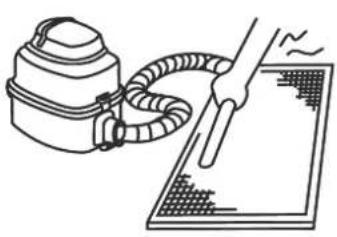
Clean the air filter with a vacuum cleaner or water.
a. The air intake side should face up when using a vacuum cleaner. (Refer to Figure 14.2)
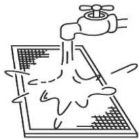
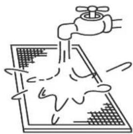
b. The air intake side should face down when using clean water. (Refer to Figure 14.3)
For excessive dusts, use a soft brush and natural detergent to clean it and dry in a cool place.
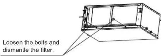
Figure 14.1
natural_image
Line drawing of a hand holding a tool next to a spray gun, with no text or symbols present.Figure 14.2
natural_image
Simple line drawing of a faucet spraying water onto a grid-patterned surface (no text or symbols)Figure 14.3

Caution
- Do not dry out the air filter under direct sunshine or with fire.
-
The air filter should be installed before the unit body installation.
-
Re-install the air filter.
- Install and close the air inlet grille by reversing steps 1 and 2, and connect the control box cables to the corresponding terminals in the main body.
- Maintenance before stopping using the unit for a long time (e.g., at the end of a season)
a. Let the indoor units run in fan only mode for about half a day to dry the interior of the unit.
b. Clean the air filter and indoor unit casing.
c. Refer to "Cleaning the air filter" for details. Install cleaned air filters back in their original positions.
d. Turn off the unit with the ON/OFF button on the remote controller, and then unplug it.

Caution
- When the power switch is connected, some energy will be consumed even if the unit is not running. Disconnect the power to save energy.
- A degree of dirt will accumulate when the unit has been used several times, which will require cleaning.
• Take of the batteries from the remote controller.
Maintenance after a long period of non-use
a. Check for and remove anything that might be blocking the inlet and outlet vents of the indoor units and outdoor units.
b. Clean the unit casing and clean the filter. Refer to "Cleaning the filter" for instructions. Re-install the filter before running the unit.
c. Turn on the power at least 12 hours before you want to use the unit to ensure it works properly. As soon as the power is turned on, the remote control display appears.
15. Symptoms That Are Not Faults
The following symptoms may be experienced during the normal operation of the unit and are not considered faults. Note: If you are not sure whether a fault has occurred, contact your supplier or service engineer immediately.
Symptom 1: The unit will not run
Symptom: When the ON/OFF button on the remote controller is pressed, the unit does not immediately start running.
Cause: to protect certain system components, system start-up or re-start is intentionally delayed for up to 12 minutes under some operating conditions. If the OPERATION LED on the unit's panel is lighting, the system is working normally and the unit will start after the intentional delay is complete.
Heating mode is running when the following panel lights are on: operation and the "DEF./FAN LED indicator.
Cause: the indoor unit activates protective measures because of the low outlet temperature.
Symptom 2: The unit emits white mist
White mist is generated and emitted when the unit starts to operate in a very humid environment. This phenomenon will stop once the humidity in the room is reduced to normal levels.
The unit occasionally emits white mist when it runs in heating mode. This occurs when the system finishes periodic defrosting. Moisture that may accumulate on the unit's heat exchanger coil during defrosting becomes mist and is emitted from the unit.
Symptom 4: Dust is emitted from the unit
This can occur when the unit first runs after a long idle period.
Symptom 5: The unit gives off a strange odor
If smells such as those of strong-smelling food or tobacco smoke are present in the room, they can enter the unit, leave trace deposits on the unit's internal components, and later be emitted from the unit.
16. Troubleshooting
16.1 General
Sections 16.2 and 16.3 describe some initial troubleshooting steps that can be taken when an error occurs. If these steps do not resolve the issue, arrange for a professional technician to investigate the problem. Do not attempt further investigations or troubleshooting yourself.
If any of the following errors occur, power the unit off, contact a professional technician immediately and do not attempt troubleshooting yourself:
a. A safety device such as a fuse or circuit breaker frequently blows/trips.
b. An object or water enters the unit.
c. Water is leaking from the unit.

Caution
- Do not attempt to inspect or repair this unit by yourself. Arrange for a qualified technician to carry out all servicing and maintenance.
16.2 Unit Troubleshooting
| Symptom Possible causes | Troubleshooting steps | |
| The unit does not start | A power cut has occurred (the power to the premises has been cut-off). | Wait for the power to come back on. |
| The unit is powered off. | Power on the unit. This indoor unit forms part of an air conditioning system that has multiple indoor units that are all connected. The indoor units cannot be powered on individually - they are all connected to one, single power switch. Ask a professional technician for advice regarding how to safely power on the units. | |
| The power switch fuse may have burned out. Replace the fuse. | ||
| The remote controller's batteries are dead. Replace the batteries. | ||
| Air flows normally but doesn't cool | The temperature setting is not correct. | Set the desired temperature on the remote controller. |
| The unit starts or stops frequently | Arrange for a professional technician to check the following:Too much or too little refrigerant.No gas in the refrigerant circuit.The outdoor unit compressors have malfunctioned.The power supply voltage is too high or too low.There is a blockage in the piping system. | |
| Low cooling effect | Doors or windows are open. Close the doors and windows. | |
| Sunlight is shining directly onto theunit. | Close shutters/blinds to shield the unitfrom direct sunlight. | |
| The room contains many heat sources such as computers or refrigerators. | Turn off some of the computers during the hottest part of the day. | |
| The unit's air filter is dirty. Clean the filter. | ||
| The outside temperature is unusually high. | The cooling capacity of the system reduces as the outdoor temperature rises and the system may not provide sufficient cooling if the local climate conditions are not considered when the system's outdoor units were selected. | |
| Engage a professional air conditioning engineer to check the following:The unit's heat exchanger is dirty.The unit's air inlet or outlet is blocked.A refrigerant leak has occurred. | ||
| Low heating effect | Doors or windows are not completely closed. | Close doors and windows. |
| Arrange for a professional technician to check the following:A refrigerant leak has occurred. | ||
16.3 Remote Controller Troubleshooting
Warning:
Certain troubleshooting steps that a professional technician may perform when investigating an error are described in this owner's manual for reference only. Do not attempt to undertake these steps yourself – arrange for a professional technician to investigate the problem.
If any of the following errors occur, power the unit off and contact a professional technician immediately. Do not attempt troubleshooting yourself:
A safety device such as a fuse or circuit breaker frequently blows/trips.
- An object or water enters the unit.
◆ Water is leaking from the unit.
| Symptom Possible causes Troubleshooting steps | ||
| The fan speed cannot be adjusted | Check whether the MODE indicated on the display is "AUTO". | In automatic mode, the air conditioner will automatically change the fan's speed. |
| Check whether the MODE indicated on the display is "DRY". | When dry mode is selected, the air conditioner automatically adjusts the fan speed. (The fan speed can be selected during "COOL", "FAN ONLY", and "HEAT".) | |
| The remote controller signal is not transmitted even when the ON/OFF button is pushed | A power cut has occurred (the power to the premises has been cut-off). | Wait for the power to come back on. |
| The remote controller's batteries are dead. Replace the batteries. | ||
| The indication on the display disappears after a certain time | Check whether the timer operation has come to an end when TIMER OFF is indicated on the display. | The air conditioner operation will stop up to the set time. |
| The TIMER ON indicator goes off after a certain time | Check whether the timer operation has come to an end when TIMER ON is indicated on the display. | Up to the set time, the air conditioner will automatically start and the appropriate indicator will go off. |
| No receiving soundfrom the indoor unit when the ON/OFF button is pressed | Check whether the signal transmitter of the remote controller is properly directed to the infrared signal receiver of the indoor unit when the ON/OFF button is pressed. | Directly transmit the signal transmitter of the remote controller to the infrared signal receiver of the indoor unit, and then press the ON/OFF button twice. |
16.4 Error Codes
With the exception of a mode conflict error, contact your supplier or service engineer if any of the error codes listed in the following table are displayed on the unit's display panel. If the mode conflict error is displayed and persists, contact your supplier or service engineer. These errors should only be investigated by a professional technician. The descriptions are provided in this manual for reference only.
| Content | Display output | Possible causes |
| Mode conflict E0 | The indoor unit's operating mode conflicts with that of the outdoor units. | |
| Communication error between indoor and outdoor units | E1 | Communication wires between indoor and outdoor units not connected properly.Interference from high voltage wires or other sources of electromagnetic radiation.Communication wire too long.Damaged main PCB. |
| Indoor ambient temperature sensor (T1) error | E2 | Temperature sensor not connected properly or has malfunctioned.Damaged main PCB. |
| Indoor heat exchanger mid-point temperature sensor (T2) error | E3 | |
| Indoor heat exchanger outlet temperature sensor (T2B) error | E4 | |
| Fan error E6 | Fan stuck or blocked.Fan motor not connected properly or has malfunctioned.Power supply abnormal.Damaged main PCB. | |
| EEPROM error E7 ♦ Damaged main PCB. | ||
| Indoor EEV coil error Eb | Line loosened or broken.The electronic expansion valve in stuck.Damaged main PCB. | |
| Outdoor unit error Ed ♦ Outdoor unit error. | ||
| Water level error EE | Water level float stuck.Water level switch not connected properly.Damaged main PCB.Drain pump has malfunctioned. | |
| The indoor unit has not been assigned an address | FE ♦ Indoor unit has not been assigned an address. |
HTW
QUALITY COMFORT EVERYWHERE
GAINABLE HAUTE PRESSION
MI2
FRANÇAIS
Installation Manuel....1
Accessoires....2
natural_image
Technical line drawing of two types of electrical insulator components (no text or symbols)Chiffre 3.2
Structure d'acier
natural_image
Technical line drawing of a rectangular enclosure with internal components and dimension label (905), no readable text or symbols beyond the dimension marker.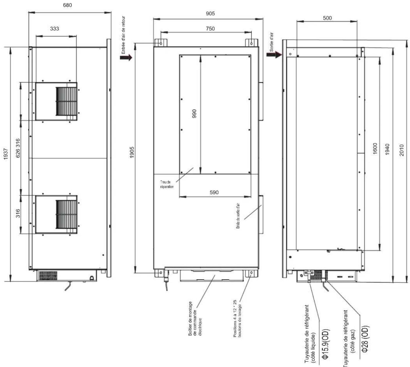
MCA: Minimum Circuit Amps
MFA: Maximum Fuse Amps
IFM: Indoor Fan Motor
kW: Rated motor output
FLA: Full Load Amps
natural_image
Simple line drawing of a woman standing next to a baby with a swirling pattern above (no text or symbols)natural_image
Illustration of a hand holding a tool next to a portable device with hoses and a grid-patterned surface (no text or symbols)Graphique 14.2

natural_image
Simple line drawing of a faucet spraying water onto a grid-patterned surface (no text or symbols)Graphique 14.3

Mise en garde
natural_image
Technical line drawing of two electrical insulator components with no text or symbolsFigura 3.2
Estrutura de ferro
natural_image
Technical line drawing of a rectangular enclosure with internal components and dimension label (905), no readable text or symbols beyond the dimension marker.
natural_image
Pure electrical circuit lines without any symbolsFigura 5.2a (without a water pump)
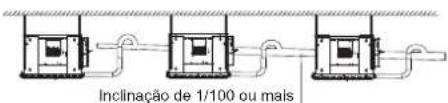
MCA: Minimum Circuit Amps
MFA: Maximum Fuse Amps
IFM: Indoor Fan Motor
kW: Rated motor output
FLA: Full Load Amps
natural_image
Simple line drawing of a woman standing beside a baby with a spiral on top (no text or symbols)natural_image
Line drawing of a hand holding a tool next to a spray bottle and a grid-patterned surface (no text or symbols)Figura 14.2

natural_image
Simple line drawing of a faucet spraying water onto a grid-patterned surface (no text or symbols)Figura 14.3

Cuidado
natural_image
Technical line drawing of two types of electrical insulator components (no text or symbols)Figura 3.2
natural_image
Technical line drawing of a rectangular enclosure with internal components and dimension label (905), no readable text or symbols beyond the dimension marker.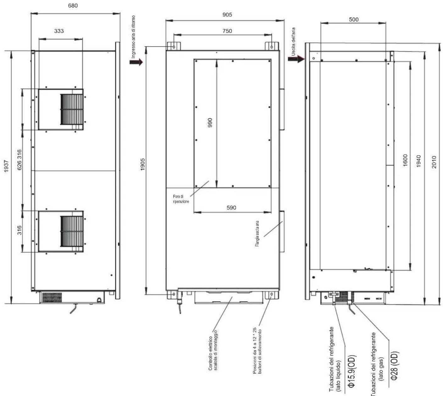
Figura 5.2b (with a water pump)
line
| Flusso d'aria (m3 / h) | 3720 | 3820 | 3920 | 4020 | 4120 | 4220 | 4320 | | ---------------------- | ---- | ---- | ---- | ---- | ---- | ---- | ---- | | 30Pa | 80 | 85 | 90 | 95 | 100 | 105 | 110 | | 60Pa | 75 | 80 | 85 | 90 | 95 | 100 | 105 | | 70Pa | 70 | 75 | 80 | 85 | 90 | 95 | 100 | | 90Pa | 65 | 70 | 75 | 80 | 85 | 90 | 95 | | 100Pa | 60 | 65 | 70 | 75 | 80 | 85 | 90 | | 110Pa | 55 | 60 | 65 | 70 | 75 | 80 | 85 | | 120Pa | 50 | 55 | 60 | 65 | 70 | 75 | 80 | | 130Pa | 45 | 50 | 55 | 60 | 65 | 70 | 75 | | 140Pa | 40 | 45 | 50 | 55 | 60 | 65 | 70 | | 150Pa | 35 | 40 | 45 | 50 | 55 | 60 | 65 | | 160Pa | 30 | 35 | 40 | 45 | 50 | 55 | 60 | | 170Pa (predefinita) | - | - | - | - | - | - | - | | 180Pa | - | - | - | - | - | - | - | | 190Pa | - | - | - | - | - | - | - | | 200Pa | - | - | - | - | - | - | - | | 210Pa | - | - | - | - | - | - | - | | 230Pa | - | - | - | - | - | - | - | | 250Pa | - | - | - | - | - | - | - | | The data is already in CSV format: 'Flusso d'aria (m3 / h)' and 'Pressure (Pa)' are not included in the image. There is only one data series in this case. The values for the 'Pressure (Pa)' series are explicitly labeled as '170Pa(predefinita)'. Error bars are present on the lines for each data point. The y-axis is labeled 'Flusso d'aria (m3 / h)'. Error bars are also labeled 'Pressure (Pa)' but do not have explicit labels. The data points are not directly plotted or labeled.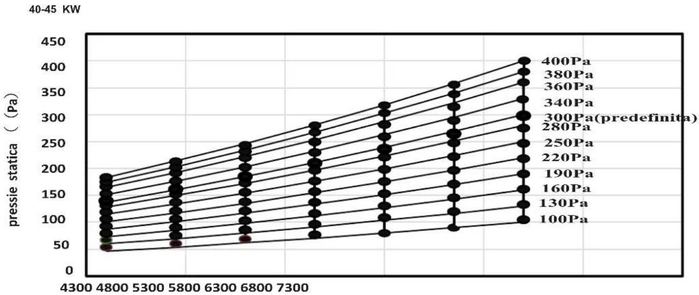
line
| Pressure (Pa) | 40-45 KW | |---|---| | 400Pa | 420 | | 380Pa | 400 | | 360Pa | 380 | | 340Pa | 360 | | 300Pa (predefinita) | 340 | | 280Pa | 320 | | 250Pa | 300 | | 220Pa | 280 | | 190Pa | 260 | | 160Pa | 240 | | 130Pa | 220 | | 100Pa | 200 |Use the same power supply, circuit breaker and leakage protective device for the indoor units connected to the same outdoor unit.
Potenza all'aperto
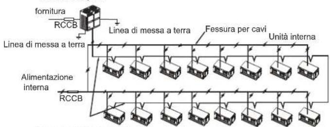
MCA: Minimum Circuit Amps
IFM: Indoor Fan Motor
FLA: Full Load Amps
MFA: Maximum Fuse Amps
kW: Rated motor output
| SW7_1 | |
| SW7[0] | Riservato |
| 0/1 definition of each dial code switch: | ||
| significa 0 | ||
natural_image
Simple line drawing of a woman standing next to a baby with a swirling pattern above (no text or symbols)natural_image
Line drawing of a hand holding a tool next to a spray bottle and a grid-patterned surface (no text or symbols)Figura 14.2

natural_image
Simple line drawing of a faucet spraying water onto a grid-patterned surface (no text or symbols)Figura 14.3

Attenzione
info@htwspain.com - www.htwspain.com
FRANCE
info@htwfrance.com
PORTUGAL
info@htw.pt
ITALIA
info.it@htwspain.com
At the end of its working life, the product must not be disposed of as urban waste. It must be taken to a special local authority deifferentiated waste collection centre or to a dealer providing this service. Disposing of a household appliance separately avoids possible negative consequences for the environment and health deriving from inappropriate disposal and enables the constituent materials to be recovered to obtain significant savings in energy and resources. As a reminder of the need to dispose of household appliances separately, the product is marked with a crossed-outwheeled dustbin.
AVERTISSEMENTS POUR L'ÉLIMINATION CORRECTE DU PRODUIT AUX TERMES DE LA DIRECTIVE 2002/96 / CE.