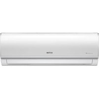
SR24 - Air Conditioning HTW - Free user manual and instructions
Find the device manual for free SR24 HTW in PDF.


User questions about SR24 HTW
0 question about this device. Answer the ones you know or ask your own.
Ask a new question about this device
Download the instructions for your Air Conditioning in PDF format for free! Find your manual SR24 - HTW and take your electronic device back in hand. On this page are published all the documents necessary for the use of your device. SR24 by HTW.
USER MANUAL SR24 HTW
natural_image
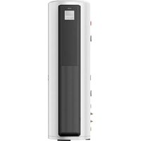
White cylindrical water heater unit with digital display and control buttons (no visible text or symbols)ESPAÑOL
natural_image
Pure electrical circuit symbol for a diode (no text or labels)natural_image
Blue circular icon with white human and child silhouettes, no text or symbols presentnatural_image
Technical line drawing of a vertical rectangular device with a small inset panel, shown in two-dimensional perspective (no text or symbols)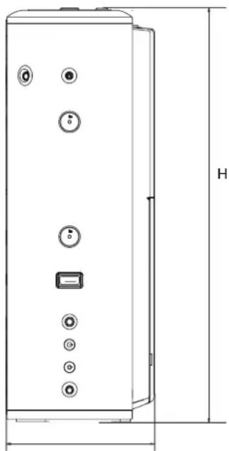
natural_image
Technical line drawing of a vertical cylindrical device with multiple buttons and a labeled height dimension (no text or symbols beyond basic geometry)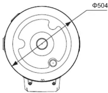
text_image
Φ504text_image
Diagram showing labeled icons and symbols with numbered labels, including circles, arrows, and checkmarksnatural_image
Illustration of a hand interacting with a smartphone displaying a user profile interface (no text or symbols on screen)text_image
Add devicetext_image
SmartHome Water Heater 40% Balance time 50% Water Heater Water Heater Balance Time Water Heater Balance Time5.5 Cumplimiento
natural_image
White cylindrical industrial air conditioner unit with digital display and control buttons (no visible text or symbols)ENGLISH
Owner's and installation manual. SR24 indoor unit

WARNING
This unit is required reliable earthing before usage, otherwise might cause death or injury.

natural_image
Pure electrical circuit symbol for a diode (no text or labels)If you can't make sure that your house power supply is earthed well, please don't install the unit. Please have a qualified person perform the reliable earthing connection and the installation of the unit. Examples of a qualified person include: licensed plumbers, authorized electric company personnel, and authorized service personnel.
!
CAUTION
• Children should be supervised to ensure that they do not play with the appliance.
- If the supply cord is damaged, it must be replaced by the manufacturer or its service agent or a similarly qualified person.
- DISPOSAL: Do not dispose this product as unsorted municipal waste. Collection of such waste separately for special treatment is necessary.
Do not dispose of electrical appliances as unsorted municipal waste, use separate collection facilities.
Contact your local government for information regarding the collection systems available.
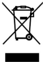
If electrical appliances are disposed of in landfills or dumps, hazardous substances can leak into the groundwater and get into the food chain, damaging your health and well-being.
- The wiring must be performed by professional technicians in accordance with national wiring regulations and this circuit diagram.
An all-pole disconnection device which has at least 3mm separation distance in all pole and a residual current device (RCD) with the rating not exceeding 30mA shall be incorporated in the fixed wiring according to the national rule.
- The handle of PTR valve should be pulled out once per half a year to make sure that there is no jam of the valve.
- The drainage pipe should be well insulated in order to prevent water inside pipe from freezing in cold weather.
- This appliance can be used by children aged from 3 years and above and persons with reduced physical, sensory or mental capabilities or lack of experience and knowledge if they have been given supervision or instruction concerning use of the appliance in a safe way and understand the hazards involved. Children shall not play with the appliance .Cleaning and user maintenance shall not be made by children without supervision Children aged from 3 to 8 years are only allowed to operate the tap connected to the water heater.(FOR EN STANDARD)
- This appliance is not intended for use by persons (including children) with reduced physical, sensory or mental capabilities, or lack of experience and knowledge, unless they have been given supervision or instruction concerning use of the appliance by a person responsible for their safety. Children should be supervised to ensure that they do not play with the appliance.
- The discharge pipe connected to PTR is to be installed in a continuously downward direction.
- The water may drip from the discharge pipe of the pressure-relief device and that this pipe must be left open to the atmosphere.
- Regarding how the water heater can be drained, thanks to refer to the below paragraphs of the manual.
- The pressure-relief device is to be operated regularly to remove lime deposits and to verify that it is not blocked.
Your safety is the most important thing we concerned!
PARTS NAMES
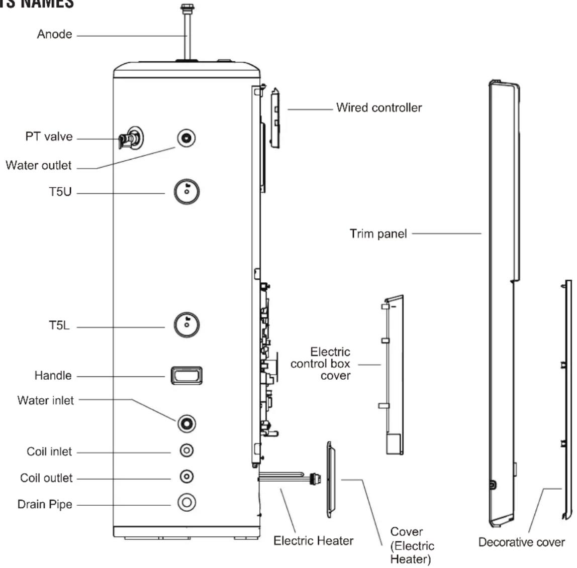
text_image
13 NAMES Anode PT valve Water outlet T5U T5L Handle Water inlet Coil inlet Coil outlet Drain Pipe Wired controller Trim panel Electric control box cover Electric Heater Cover (Electric Heater) Decorative coverWhen ordering repair parts please always give the following information:
1) Model, serial and product number.
2) Parts name.

NOTE
All the picture in this manual are for explanation purpose only.
They may be slightly different from the heat pump water heater you purchased (depend on model). Please refer to the real sample instead of the picture of this manual.
CONTENTS PAGE
BASIC OPERATION PRINCIPLE....03
SAFETY INFORMATION....03
BEFORE INSTALLATION....05
INSTALLATION....09
TRIAL-RUNNING....13
OPERATION 15
TROUBLE SHOOTING....20
MAINTENANCE.... 25
0. BASIC OPERATION PRINCIPLE
As we know with our experience, the natural flow of heat, which moves from a higher to a lower temperature source. The heat pump can transfer heat from a lower temperature source to a higher temperature source with high efficiency.
The advantage of a heat pump water heater is that it can supply more heat energy, normally 3 times than input electricity power by extracting the heat from ambient atmosphere in a free charge way to Sanitary Hot Water, compare to the traditional water heater, such as electric water heater or gas burner water heater, their efficiency is normally less than 1, which means it will dramatically cut off the bill of family daily SHW by the application of heat pump water heater, following data will show more details.
Power consumption comparison under the same condition to heat 1 ton water from 15°C to 55°C
The equivalent heat load Q=CM(T1-T2)=1(kCal/kg*°C)
X1000(kg)*(55-15)(°C)=40000kCal=46.67kW*h
Table. 0-1
| HPWH Gas | Burner E-heater | ||
| Energy Resource | Air,Electricity Gas | Electricity | |
| Transfer Factor | 360kCal/kW*h | 24000kCal/m3 | 860kCal/kW*h |
| Average Efficiency (W/W) | 3.5 0.8 0.95 | ||
| Energy Consumption | 13.33kW*h | 2.08m3 | 49.13 kW*h |
| Unit Cost | 0.09 USD/kW*h | 2.84 USD/m3 | 0.09 USD/kW*h |
| Running Cost USD | 1.2 | 5.9 | 4.42 |
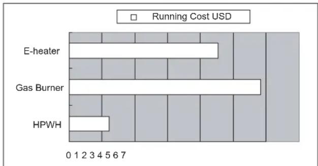
bar
| Category | Running Cost USD | |---|---| | E-heater | 100 | | Gas Burner | 100 | | HPWH | 50 |Fig.0-1

NOTE
Above calculation is based on the ideal condition, the final cost bill will be different caused by the actual running conditions, such as running period, ambient temperature, etc.
1. SAFETY INFORMATION
Please read thoroughly all of the instructons before installing or operating the unit.
Following safety symbols are very important, always read and obey all safety symbols:
 | CAUTION | You may be injured if you don't obey instructions. |
 | WARNING | You may be killed or seriously injured if you don't obey instructions. |
 | DANGER | You may be killed or seriously injured immediately if you don't obey instructions. |

WARNING
• The unit must be earthed effectively.
- A creepage breaker must be installed adjacent to the power supply.
- Do not remove, cover or deface any permanent instructions, lables, or the data label from either the outside of the unit or inside of unit panels.
- Ask qualified person to perform the installation of this unit in accordance with local national regulations and this manual. Improper installation may result in water leakage, electric shock or fire.
- Ask qualified person for relocating, repairing and maintaining the unit instead of doing by yourself. Improper installation may result in water leakage, electric shock or fire.
- Electric connection work should obey the instructions of local power company, local electric utility and this manual.
- Never use the wire and fuse with wrong rated current, otherwise unit may break down and cause fire furthermore.
- Never use a flammable spray such as hair spray, lacquer paint near the unit.
- It may cause a fire.
- If the supply cord is damaged, it must be replaced by the manufacturer or its service agent or a similarly qualified person.

BATTERY WARNING
WARNING: Contains button or coin cell battery.
- WARNING: The battery is hazards and KEEP OUT OF REACH OF CHILDREN
(Whether the battery is new or used).
If the battery compartment(if applicable) does not close securely, stop using the product and keep it away from children.
- For appliances which contain coin or lithium batteries:

BATTERY WARNING
KEEP OUT OF REACH OF CHILDREN.
Swallowing can lead to chemical burns, perforation of soft tissue, and death. Severe burns can occur within 2 hours of ingestion. Seek medical attention immediately.

natural_image
Blue circular icon with white pictograms of a adult and child, no text or symbols present- For appliances which contain button or non-lithium batteries.
- The battery can cause serious injuries if it is swallowed or placed inside any part of the body. - If you think batteries might have swallowed or placed inside any part of the body, seek immediate medical attention.

BATTERY NOTES
If it is suspected a button/coin battery has been swallowed or otherwise placed inside any part of the body, a person should contact the Australian Poisons Information Centre on 13 11 26 immediately for 24/7fast, expert advice.

BATTERY DISPOSAL
- Dispose of used button/coin batteries immediately.
- Place sticky tape around both sides of the battery and dispose of it immediately in an outside bin, out of reach of children, or recycle safely.

CAUTION
- The earthing pole of socket must be grounded well, make sure that power supply socket and plug are dry enough and connected tightly.
- How to check the power supply socket and plug are qualified?
Turn on power supply and keep the unit running for a half hour, then turn off power supply and plug out, check whether the socket and plug is hot or not.
- Before cleaning, be sure to stop the operation and turn the breaker off or pull out the power plug. Otherwise, an electric shock and injury may be caused.
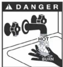
• Water temperature over 50°C
can cause severe burns instantly or death from scalds. Children, disabled and elderly are at highest risk of being scalded. Feel water before bathing or showering.
text_image
DANGER HOT BURNWater temperature limiting valves are recommended.
- Do not operate the unit with a wet hand. An electric shock may be caused.
- The installation height of power supply should be over 1.8m, if there is any water spattered, separate the power supply from water.
- A one-way valve must be installed on the water inlet side, which is available from accessories, see manual "accessories" part.
- It's normal if some water drops from the hole of PT valve during operation. But, if there is a great amount of water, call your service agent for instructions.
• After a long term use, check the unit base and fittings. - If damaged, the unit may sink and result in injury.
- Arrange the drain pipe to ensure smooth draining.
- Improper drainage work may cause wetting of the building, furniture etc.
- Do not touch the inner parts of the controller.
- Do not remove the front panel. Some parts inside are dangerous to touch, otherwise a machine malfunction may be caused.
- Do not turn off the power supply.
- System will stop or restart heating automatically. A continuous power supply for
water heating is necessary, except service and maintenance.
- If the unit has not been used for a long period of time(2 weeks or more), hydrogen gas will be produced in the water piping system.
- Hydrogen gas is extremely flammable. To reduce the risk of injury under these conditions, it is recommended that open the hot water tap for several minutes at the kitchen sink before using any electrical appliance connected to the hot water system. When hydrogen is present, there will probably be an unusual sound such as air escaping through the pipe as the water begins to flow. There should be no smoking or open flame near the tap at the time it is open.
2. BEFORE INSTALLATION
2.1 Unpacking
2.1.1 Accessories
| Accessory Name Qty. | Sharp | Purpose | |
| Owner's & Installation Manual | 1 | Installation and use instructionThis manual | |
| One Way Valve | 1 | Prevent water fromflowing backwards | |
| Technical Parameter Table | 1 | Introduction of technical parameters | |
| Water Pipe Joint | 2 | Connect the inlet and outlet water pipes | |
| Fixed Strip | 1 | Fixed water tank |
| Accessory Name Qty. | Sharp | Purpose | |
| Owner's & Installation Manual | 1 | Installation and use instructionThis manual | |
| One Way Valve | 1 | Prevent water fromflowing backwards | |
| Technical Parameter Table | 1 | Introduction of technical parameters | |
| Water Pipe Joint | 2 | Connect the inlet and outlet water pipes | |
| Fixed Strip | 1 | Fixed water tank |
2.1.2 How to transport
1) In order to avoid scratch or deformation of the unit surface, apply guard boards to the contacting surface.
No contact of fingers and other things with the vanes.
Don't incline the unit more than 15^ in moving, and keep it vertical when installing.
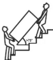
Gradient limit>75°
2) This unit is heavy, it need to be carried by two or more persons, otherwise might cause injury and damage.
2.2 Location requirements
1) Enough space for installation and maintenance shall be preserved.
2) The base surface should be flat, surface should be inclined no more than 2^ and able to bear the weight of the unit and suitable for installing the unit without increasing noise or vibration.
3) No flammable gas is leaked nearby.
4) Recommending install the main uint at indoor ambient range of 5\~43°C. It is not allowed to install the unit at outdoor or rain achieving place. The ambient temperature around the indoor unit must be ≥5°C to prevent water form freezing.
5) It is convenient for piping and wiring.
6) If the unit has to be installed on a metal part of building, make sure the well electric insulation which should meet the relevant local electric standard.
7) The floor at the place of installation must be waterproof and have a proper drainage, in order to limit the extent of damage in case of water leakage. It is the responsibility of the installer to ensure that installation and draining works are compliant with regulations.
8) The unit shall not be installed in locadtons where it is exposed to oil, smoke, dust or particles, such as kitchens or factories.

CAUTION
- The ambient air temperature must also be considered when installing this unit, in heat pump mode the ambient air temperature must be Within operating temperature. If the ambient air temperature falls outside these upper and lower limits, the electrical elements will be activated to meet the hot water demand and the heat pump does not operate. Electric heating replaces heat pump operation to heat hot water.
- For the specific operating range of the outdoor unit, please refer to the outdoor unit's instruction manual
- The unit should be located in an area not subject to freezing temperatures. The unit located in unconditioned spaces(i.e., garages, basements, etc.) may require the water piping, condensate piping, and drain piping to be insulated to shelter against freezing.
Installing the unit in any of the following places may lead to malfunction(If it is inevitable, consult the supplier).
- The site contains mineral oils such as lubricant of cutting machines.
- Seaside where the air contains much salt.
- Hot spring area where corrosive gases exist, e.g., sulfide gas.
• Factories where the power voltage fluctuates seriously. - Inside a car or cabin.
- The place with direct sunlight and other heat supplies. If there's no way to avoid these, please install a covering.
- Place like kitchen where oil permeates.
- Place where strong electromagnetic waves exist.
- Place where flammable gases or materials exist.
- Place where acid or alkali gases evaporate.
- Other special environments.
A discharge pipe connected to the pressure-relief device is to be installed in a continuously downward direction and in a frost-free environment.

WARNING
- The unit must be securely fixed, elsewise, noise and shaking may be resulted.
- Make sure that there's no obstacle around the unit.
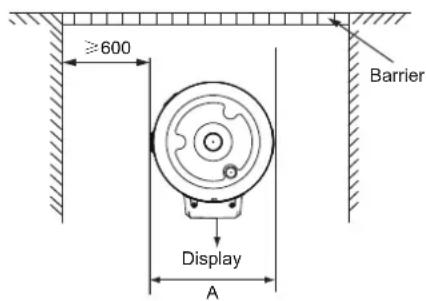
2.3 Maintenance space requirements (unit: mm)
text_image
≥600 Barrier Display A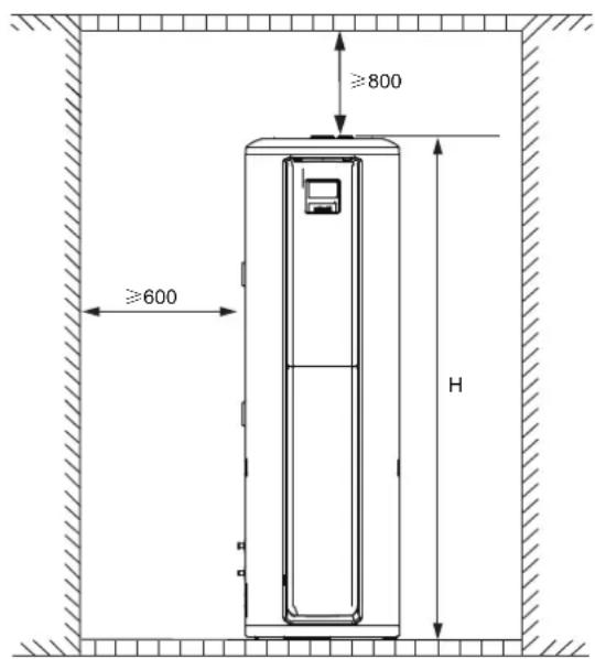
text_image
≥800 ≥600 H| Overall dimensions unit: mm | |||
| Dimension Model | A B H | ||
| 190L 504 1660574 | |||
2.5 Unit outline dimension (unit: mm)
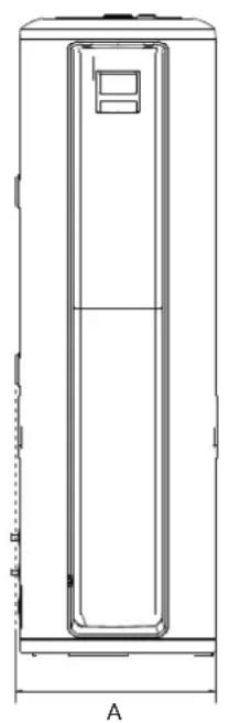
natural_image
Technical line drawing of a vertical rectangular device with a central panel and top handle, labeled 'A' at bottom (no text or symbols on the diagram itself)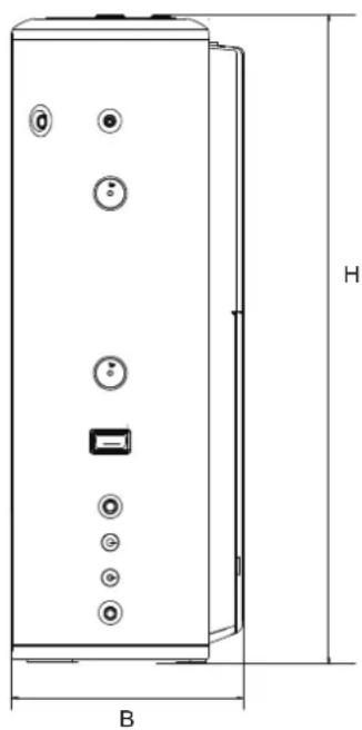
natural_image
Technical line drawing of a vertical cylindrical device with multiple buttons and a labeled height dimension (no text or symbols beyond labels)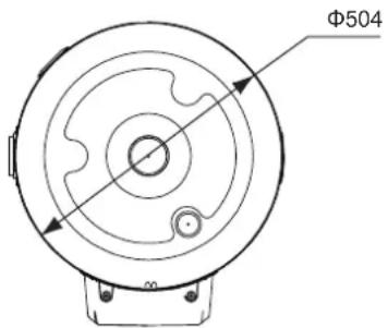
text_image
Φ5042.6 Installation guidelines

CAUTION
- The tank is intended to be installed in an indoor environment with an ambient temperature range of 5\~43°C. The ambient temperature around the indoor unit must be ≥5°C to prevent water form freezing.
- In order to effectively fix the water tank, please make sure that the water tank is placed on a flat and hard concrete floor.
- Please ensure that the water outlet at the bottom of the water tank has been filled with water before the water tank.
Handling and Installation of water tank
- The water tank is soft and heavy, need more than two people to carry and install, otherwise it is easy to cause the machine to ingest and destroy into casualties.
- Please carry the water tank according to the factory state, do not disassemble it by yourself.
- In order to avoid surface abrasion and deformation, please put a guard on the surface of the body in contact with hard objects.
- Please ensure the vertical and reliable installation of the tank and the necessary space for installation and maintenance.
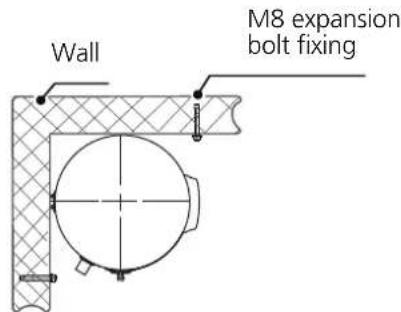
Fixing method

WARNING
- The appearance of the water tank and the orientation of the water tank orifice are for reference only and can be adjusted according to the actual installation.
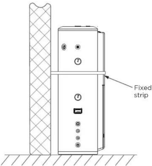
- The position of the fixed strip up and down can be adjusted according to the actual situation.
- The length of the expansion bolt is not less than 90mm.
Water heater fixing steps are as follows:
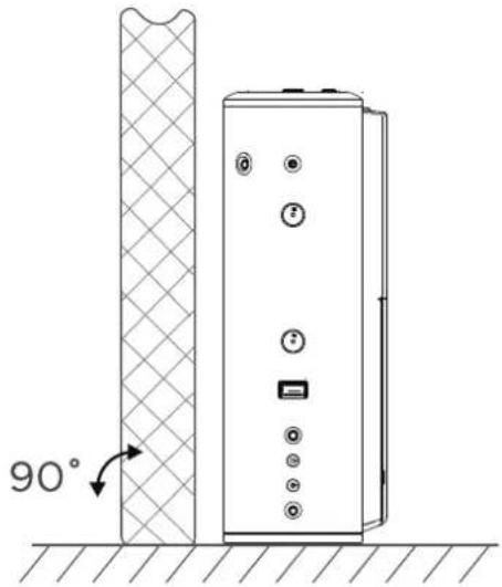
- First place the water tank only against the wall and the ground hard and flat position, so that the tank vertical ground.
- Connect the connection pipes and water pipes of the internal and external units according to the installation instructions.
• Install the expansion bolts in the wall according to the drawing. - Fix the end with less holes for mounting the fixing strip on the expansion bolt.
- Tighten the fixing strip to the appropriate hole position, and then fix it with a screw on another expansion bolt.
- If the fixed strip has extra please cut off.
- After the installation is completed, check whether the water tank is safely and securely fixed.
2.4 If installed in inclosed space
The water heater must be located in a space >15m^3 , and must have unrestricted air flow. As an example, a room that has an 2.5 tall ceiling and is 3 meter long by 2 meter wide would contain 15m^3 .
text_image
90°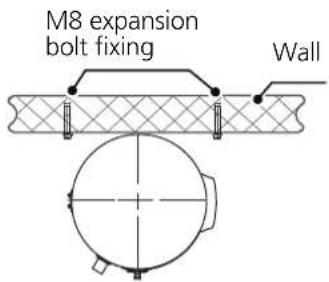
text_image
M8 expansion bolt fixing WallOne side wall (top view)
text_image
Wall M8 expansion bolt fixingCorner wall (top view)
text_image
Fixed strip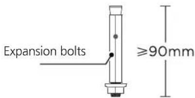
text_image
Expansion bolts ≥90mmNOTE: Installation of outdoor units or other packaged products can be found in the Owner's Manual & Installation Manual.
3. INSTALLATION
3.1 Water System Piping
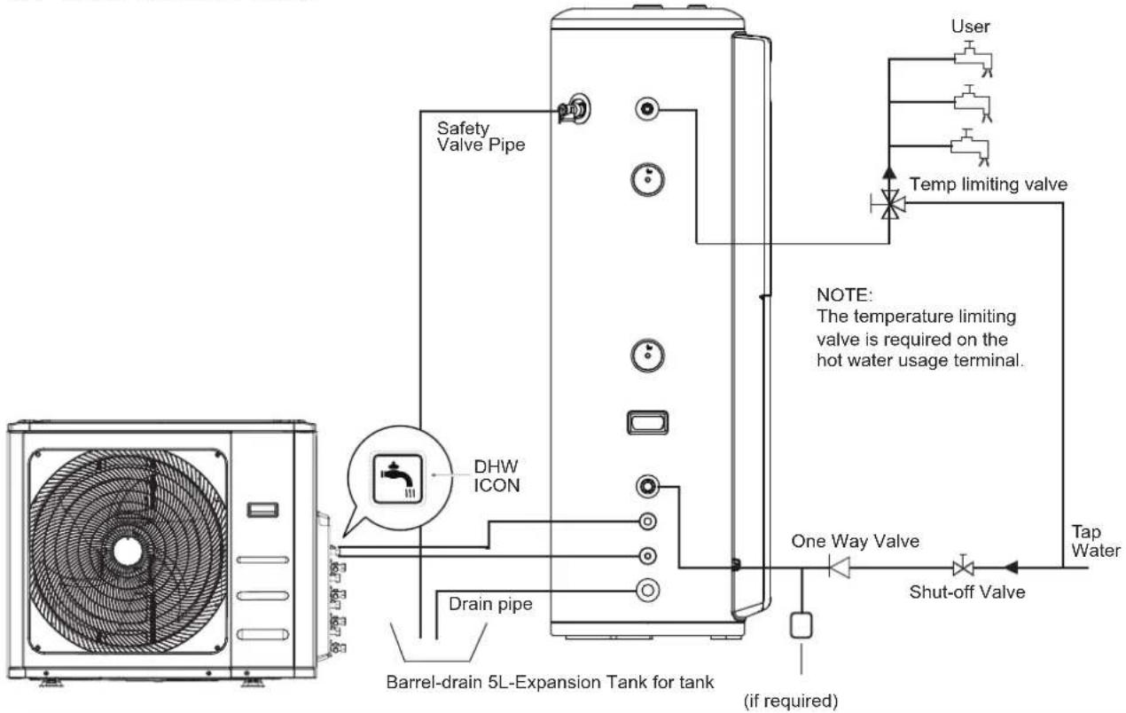
flowchart
graph TD
    A["HVAC"] --> B["DHW ICON"]
    B --> C["Safety Valve Pipe"]
    C --> D["Barrel-drain 5L-Expansion Tank for tank"]
    D --> E["Drain pipe"]
    E --> F["One Way Valve"]
    F --> G["Tap Water"]
    G --> H["Shut-off Valve"]
    H --> I["User"]
    I --> J["Temp limiting valve"]
    J --> K["NOTE: The temperature limiting valve is required on the hot water usage terminal."]
    style A fill:#f9f,stroke:#333
    style D fill:#ccf,stroke:#333
    style G fill:#cfc,stroke:#333
Accessories Function Installation Requirements
| Shut-off Valve | The switch acts to cut off the water path. Must be installed, selected according to the water pipe diameter. |
| One Way Valve | One-way check to prevent backflow in the water line. Must be installed, accessories factory matched. |
| Expansion tank | Maintains constant water supply pressure. Recommended installation, optional according to the specification of 5L. |
| Temp limiting valve | Outgoing water temperature is too high for mixing. Must be installed, selected according to the water pipe diameter. |
Water inlet or outlet pipes: The spec of the water inlet or outlet thread is RC3/4" (external thread). Pipes must be heat-insulated well.
1) Installation of the pipe for PTR valve: The spec of the valve connecting thread is RC3/4" (internal thread). After installation, it must be confirmed that the drainpipe outlet is exposed in the air.

CAUTION
- Piping water system as the above figure. In case of installing it at a place where outside temperature below freezing point, insulation must be provided for all hydraulic components. The handle of PTR valve should be pulled out once per half a year to make sure that there is no jam of the valve.
- Please beware of burn, beware of the hot water from the valve.
The drainage pipe should be well insulated in order to prevent water inside pipe from freezing in cold weather. - There is a risk of freezing if the tank is located in an ambient temperature below 0°C. To avoid freezing the water tank, empty the tank without powering it up. (the unit stays energized to protect the tank to a certain extent).
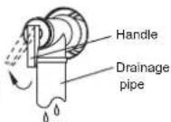

WARNING
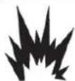
Do not dismantle the PTR Valve. Do not block off the drainage pipe. It will cause explosion and injury, if do not comply with the above instruction.
EXPLOSION
2) Installation of the One Way Valve: The spec of the One Way Valve thread in accessories is RC3/4". It is used to prevent water from flowing backwards.
3) After water system piping work, turn on the cold water inlet valve and hot water outlet valve and start effusing the tank. When water flow smoothly out from water outlet pipe(tap water outlet), the tank is full, turn off all valves and check pipeline to make sure there is not any leakage.
4) If the inlet water pressure is less than 0.15MPa, a pump should be installed at the water inlet.
For guarantee the safety usage of tank at the condition of water supply pressure higher than 0.65MPa, a reducing valve should be installed at the water inlet pipe.
5) Condensate may be leaked from unit if drainage pipe is blocked or unit operates in high humidity environment, a drainage pan is recommended as shown as following figure:
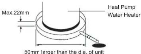
text_image
Max.22mm 50mm larger than the dia. of unit Heat Pump Water Heater3.2 Refrigerant circuit
3.2.1 General notes R32 refrigerant
This appliance is filed with R32, an odourless flammable refrigerant gas with low burning velocity (A2L class pursuant to ISO 817). If the refrigerant is leaked, there is a possibility of ignition if it enters in contact with an external ignition source. Make sure that unit installation and refrigerant piping installation comply with applicable legislation in each country. Also, in Europe, EN378 must be complied, as it is the applicable standard.
3.2.2 Refrigerant piping
Refrigerant piping length between indoor unit and outdoor unit
NOTE: For specific installation guidelines, please refer to the Outdoor unit
Refrigerant piping size
Piping connection size of outdoor unit and indoor unit
| Outdoor unit Indoor unit | |||||
| Model | Pipe size | Model | Pipe size | ||
| Gas pipe Liquid | pipe Gas pipe Liquid pipe | ||||
| M4OA-27HFN8-Q(HRU) | ∅9.52 (3/8") ∅ | 6.35 (1/4") | PLSX-190(30)/DN8-A | ∅9.52 (3/8") | ∅ 6.35 (1/4") |
The unit installation and refrigerant piping should comply with the relevant local and national regulations for the designed refrigerant. Due to R32 refrigerant and depending on fial refrigerant charge amount, a minimum flor area for installation must be considered. If total refrigerant charge amount <1.84kg, there are no additional minimum flor area requirements.
Minimum area requirements
In case of total refrigerant amount ≥ 1.84 kg, the unit should be installed, operated and stored in a room with a flor area larger than the minimum criteria. Use following graphic and table to determine these minimum criteria:
| Refrigerant Amount (kg) | Minimum Area (m2) (H:2.2m) |
| 1.84 28.81 | |
| 1.9 30.72 | |
| 2.0 34.09 | |
| 2.1 37.50 | |
| 2.2 41.36 | |
| 2.3 45.00 | |
| 2.4 49.09 | |
| 2.5 53.18 | |
| 2.6 57.73 | |
| 2.7 61.82 | |
| 2.8 66.82 | |
| 2.9 71.36 |
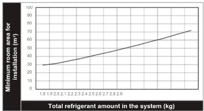
line
| Total refrigerant amount in the system (kg) | Minimum room area for installation (m²) | | ------------------------------------------ | -------------------------------------- | | 1.8 | 30 | | 1.9 | 32 | | 2.0 | 34 | | 2.1 | 36 | | 2.2 | 38 | | 2.3 | 40 | | 2.4 | 42 | | 2.5 | 44 | | 2.6 | 46 | | 2.7 | 48 | | 2.8 | 50 | | 2.9 | 52 | | 3.0 | 54 | | 3.1 | 56 | | 3.2 | 58 | | 3.3 | 60 | | 3.4 | 62 | | 3.5 | 64 | | 3.6 | 66 | | 3.7 | 68 | | 3.8 | 70 | | 3.9 | 72 | | 4.0 | 74 |NOTE: In case of not achieving the minimum flor area, contact with your dealer.
3.2.3 Refrigerant charge
Refrigerant charge amount
Please refer to the installation and operation manual of the outdoor unit for the refrigerant filling quantity.
3.3 Electric Connection

CAUTION
- The power supply should be an independent circuit with rated voltage.
• Power supply circuit should be earthed effectively. - The wiring must be performed by professional technicians in accordance with national wiring regulations and this circuit diagram.
- An all-pole disconnection device which has at least 3mm separation distance in all pole and a residual current device (RCD) with the rating of above 10mA shall be incorporated in the fixed wiring according to the national rule.
- Set the electric leakage protector according to the relevant electric technical standards of the state.
- The power cord and the signal cord shall be laid out neatly and properly without mutual interference or contacting the connection pipe or valve.
• After wire connection, check it again and make sure the correctness before power on.
- When installing the prototype, pay attention to install the signal cable of the water tank to the place where the user can't touch it.
3.3.2 Specifications of Power Supply
Table. 3-2
| Model Name | PLSX-190(30)DN8-A |
| Power Supply | 220-240V~ 50Hz |
| Mlin. Diameter of Power Supply Cord (mm2) | 1.5(For water tank with electric heating) |
| Earth Cord (mm2) | 1.5(For water tank with electric heating) |
| Manual Switch(A) Capcity/Fuse (A) | 30/20(For DHW) |
| Creepage Breaker | (Not including) |
- Please choose the power cord according to above table, and it should comply with local electric standard.
- The power cord model, recommended power cord mode is H05RN-F.

WARNING
The unit must be installed with an Creepage Breaker near the power supply and must be effectively earthed.
3.3.1 Electric Wiring Illustration
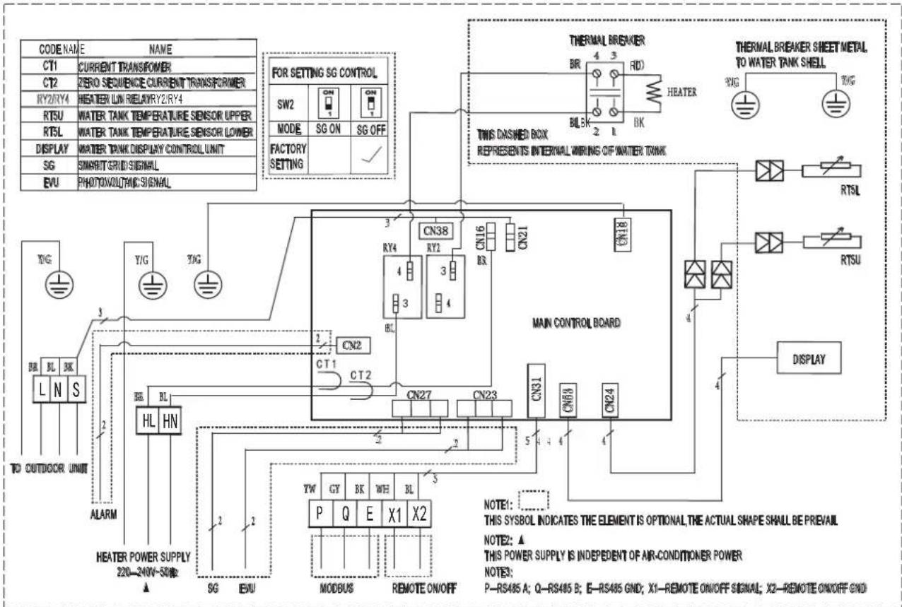
text_image
CODE NAME NAME CT1 CURRENT TRANSFORMER CT2 ZERO SEQUENCE CURRENT TRANSFORMER RY2/RY4 HEATER LIN RELAYRY2/RY4 RTSU WATER TANK TEMPERATURE SENSOR UPPER RTSL WATER TANK TEMPERATURE SENSOR LOWER DISPLAY WATER TANK DISPLAY CONTROL UNIT SG 3MABIT GRID SIGNAL EVU PHOTONOLTAIC SIGNAL FOR SETTING SG CONTROL SW2 CN 1 CN 1 MODE SG ON SG OFF FACTORY SETTING THERMAL BREAKER BR 4 3 RD HEATER BL BK 2 1 BK THIS DASHED BOX REPRESENTS INTERNAL WIRING OF WATER TANK MAIN CONTROL BOARD CN38 RY2 CN16 CN21 CN18 CN27 CN23 CN31 CN68 CN24 TW GY BK WE BL 3 P Q E X1 X2 MODBUS REMOTE ON/OFF THE METER SHEET METAL TO WATER TANK SHELL RDG TG RDG TG RTSL RTSU DISPLAY TO OUTDOOR UNIT ALARM HL HN Y/G Y/G 3 2 1 2 3 4 5 4 4 4 4 4 4 4 4 4 4 4 4 4 4 4 4 4 4 4 4 4 4 4 4 4 4 4 4 4 4 4 4 4 4 4 4 4 4 4 4 4 4 4 4 4 4 4 4 4 4 200-200V-50Hz NOTE: THIS SYMBOL INDICATES THE ELEMENT IS OPTIONAL, THE ACTUAL SHAPE SHALL BE PREVAIL. NOTE2:▲ THIS POWER SUPPLY IS INDEPENDENT OF AIR-CONDITIONER POWER. NOTE3: P-RS485 A; Q-RS485 B; E-RS485 GND; X1-REMOTE ON/OFF SIGNAL; X2-REMOTE ON/OFF GND3.3.3 Switch setting
• PCB has 2 bits of switches.
| For setting SG control | ||
| SW2 |  |  |
| MODE | SG ON SG OFF | |
| FACTORY SETTING | √ | |
3.3.4 System wiring diagram
The units of water tank can only be connected to the system of DHW. The units shall be connected according to the following electric diagrams, depending on the applicable powering scheme and according to the local regulations:
In the case of independent supply to the tank and to the outdoor unit: (The electric heating power supply line must be connected.)
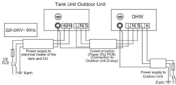
flowchart
graph TD
    A["220-240V~ 50Hz"] --> B["Power supply to electrical heater of the tank and OU"]
    B --> C["Earth"]
    D["Tank Unit Outdoor Unit"] --> E["HLHN L N S"]
    D --> F["DHW L N S L N"]
    G["CB ELB"] --> B
    H["Communication (Power IDU PCB) (Connection to Outdoor Unit D-way)"] --> D
    I["Power supply to Outdoor Unit"] --> J["Earth"]
Fig.3-13
3.4 Installation checklist
3.4.1 Location
- The flooring beneath the water heater must be able to support the weight of the unit when filled with water.
- Located indoors (such as a basement or garage) and in a vertical position. Sheltered from freezing temperatures.
- Provisions made to shelter the area from water damage. Metal drain pan installed and piped to an adequate drain.
- Sufficient space to service the water heater.


- The unit cannot be placed into any type of closet or small □ enclosure.
- The site location must be free from any corrosive elements in the atmosphere such as sulfur, fluorine, and chlorine. These elements are found in aerosol sprays, detergents, bleaches, cleaning solvents, air fresheners, paint, and varnish removers, refrigerants, and many other commercial and household products. In addition excessive dust and lint may affect the operation of the unit and require more frequent cleaning.
- The ambient air temperature must be above -15^ and below 43^ . If the ambient air temperature falls outside these upper and lower limits the electrical elements will be activated to meet the hot water demand.
3.4.2 Water System Piping
- PTR valve(Temperature and pressure relief valve) properly installed with a discharge pipe run to an adequate drain and sheltered from freezing.
- All piping properly installed and free of leaks.
- Unit completely filled with water.
- Water temperature limit valve or mixer tap(recommended) □ installed per manufacturer's instructions.
3.4.3 Condensate Drain Line Installation
- Must be located with access to an adequate drain or condensate pump.
- Condensate drain lines installed and piped to an adequate □ drain or condensate pump.
3.4.4 Electrical Connections
• The water heater requires 230 VAC for proper operation.
- Wiring size and connections comply with all local applicable codes and the requirements of this manual.
• Water heater and electrical supply are properly grounded.
- Proper overload fuse or circuit breaker protection installed.
3.4.5 Post Installation Review
- Understand how to use the User Interface Module to set the various parameters and functions.
- Understand the importance of routine inspection/maintenance of the condensate drain pan and lines. This is to help prevent any possible drain line blockage resulting in the condensate drain pan overflowing.
4. TRIAL-RUNNING
4.1 Water affusion before operation
Before using this unit, please follow the steps below.
Water Affusion: If the unit is used for the first time or used again after emptying the tank, please make sure that the tank is full of water before turning on the power.
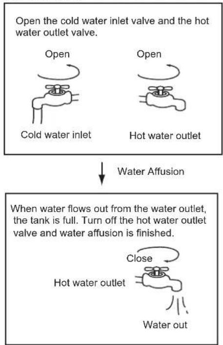
flowchart
graph TD
    A["Open the cold water inlet valve and the hot water outlet valve."] --> B["Cold water inlet"]
    C["Open the hot water outlet"] --> D["Hot water outlet"]
    B --> E["Water Affusion"]
    D --> E
    E --> F["When water flows out from the water outlet, the tank is full. Turn off the hot water outlet valve and water affusion is finished."]
    F --> G["Close"]
    G --> H["Hot water outlet"]
    H --> I["Water out"]

CAUTION
- Operation without water in water tank may result in the damage of auxiliary E-heater. Due to such damage, manufacturer will not be liable for any damages caused by this issue.
• After powered on, the display lights up. Users can operate the unit through the buttons under the display.
- Emptying: If the unit needs cleaning, moving etc, the tank should be emptied.
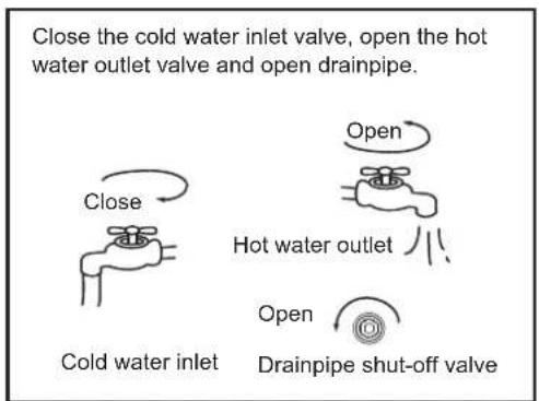
flowchart
graph TD
    A["Cold water inlet"] --> B["Open"]
    B --> C["Hot water outlet"]
    C --> D["Open"]
    D --> E["Drainpipe shut-off valve"]
    style A fill:#f9f,stroke:#333
    style B fill:#ccf,stroke:#333
    style C fill:#cfc,stroke:#333
    style D fill:#fcc,stroke:#333
    style E fill:#cff,stroke:#333
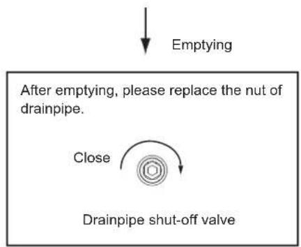
text_image
Emptying After emptying, please replace the nut of drainpipe. Close Drainpipe shut-off valve4.2 Trial- running
4.2.1 Checking list before commissioning.
1) Checking list before trial-running.
2) Correct installation of the system.
3) Correct connection of water/air piping and wiring.
4) Condensate draining smoothly well insulation work for all hydraulic part.
5) Correct power supply.
6) No air in the water pipeline and all valves opened.
7) Effective electric leakage protector installation.
8) Sufficient inlet water pressure (between 0.15MPa and 0.65MPa).
4.2.2 About Running
1) System Structure Figure
Unit has two kinds of heat sources: heat pump(compressor) and electric heater.
Unit will automatically select heat sources to heat water to the target temperature.
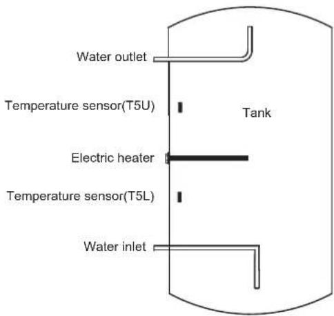
text_image
Water outlet Temperature sensor(T5U) Electric heater Temperature sensor(T5L) Water inlet TankFig.4-3
2) Water Temperature Display
The temperature shown on the display depends on the maximum of the upper sensor and the lower sensor.
3) Heat source will be automatically selected by unit. But manually E-Heater operation is available.
- Running Temperature Range Setting water temperature target range: 38\~70°C. Electrical heater running ambient temperature range: -20\~47°C. Water temperature limits:
unit: C
| Model | M4OA-27HFN8-Q (HRU) +PLSX-190(30)/DN8-A | |||||
| Ambient Temp.(T4) | T4<-18 | -18<T4≤-12 | -12<T4≤-7 | -7<T4≤-2 | -2<T4≤2 | 2<T4≤7 |
| DHW | -- | 40 | 45 | 45 | 50 | 55 |
| COOL+DHW | -- | 40 | 45 | 45 | 50 | 52 |
| Ambient Temp.(T4) | 7<T4≤15 | 15<T4≤30 | 30<T4≤43 | 43<T4≤50 | 50<T4 | |
| DHW | 55 | 52 | 50 | --- | ||
| COOL+DHW | 52 | 52 | 50 50 | -- | ||
4) Heat Source Shift
- If the target setting water temperature is higher than Max. temp(Heat pump), the unit will activate heat pump firstly to the Max. temperature, then stop heat pump, activate E-heater to continually heat water to the target temperature.
- If manually activate the E-heater running when heat pump running, E-heater and heat pump will work together until the water temperature gets to target temperature. So if want to heat quickly, please manually activate E-heater.

NOTE
- E-heater will be activated once for the current heating progress, if want to apply E-heater again, please push again.
- If only use E-heater, to heat water, so must set higher target water temperature if ambient temperature is out of heat pump running range.
4.2.3 Basic function
1) Weekly disinfect function
Under disinfection unit immediately start to heat water up to 70°C to kill the potential legionella bacteria inside water of tank, icon will light on the display screen during disinfection. Unit will quit disinfection if water temperature is higher than 70°C and extinguish icon.
2) Vacation function
Press the Ⓜ button to select VACATION, unit will automatically heat water to 15°C for the purpose of energy saving during vacation days.
3) Remote shutdown function: Users can connect a switch. If the switch is closed, the unit will be stopped forcibly. If switch breaks, the unit can run normally according settings.
4.2.4 Search function
Press and hold the ○ button for 1 second then system running parameters will be shown one by one with following sequence by each pushing of ∧ or ∨ button.
| No. | Hour low bit | Min. high bit | Min. Low bit | unit | Explanation |
| 0 | T | S | U | Temp./°C | T5U |
| 1 | T | S | L | Temp./°C | T5L |
| 2 | T | S | I | Temp./°C | --- |
| 3 | T | S | Temp./°C | Heat pump stop temp | |
| 4 | T | 3 | Temp./°C | T3 | |
| 5 | T | 4 | Temp./°C | T4 | |
| 6 | T | P | Temp./°C | TP | |
| 7 | T | H | Temp./°C | --- | |
| 8 | o | n | Outdoor unit operating mode | 0: Shutdown1: Cooling2: Heating3: Air supply4: Dehumidification5: /6: Forced cooling7: Defrosting8: Self-cleaning9: /10: Forced defrosting11: /12: Hot water production | |
| 9 | T | F | r | Outdoor unit operating frequency | Split type display actual operating frequency |
| 10 | T | T | Temp./°C | Sterilization temperature | |
| 11 | C | o | Current | Current value | |
| 12 | F | O | Wind speed range | --- | |
| 13 | E | o | Parameters checksum | 0~255 | |
| 14 | E | E | r | Electronic expansion valve opening | --- |
| 15 | E | E | C | Heat pump energy demand | 0: NO1: YES |
| 16 | P | U | P | Water pump | --- |
| 17 | P | S | One-way solenoid valve | --- | |
| 18 | F | T | Fan type | --- | |
| 19 | H | T | Electric heating control | Electric heating control type(0: Single water temperature control;1: Dual water temperature control) | |
| 20 | H | P | Heat pump control | Heat pump control type(0: Single water temperature control;1: Dual water temperature control) | |
| 21 | F | S | I | Compressor electromechanical heating belt | --- |
| 22 | S | I | o | Water tank capacity | |
| 23 | P | 4 | P | Four-way valve | --- |
| 24 | U | U | Machine type | 0: Integral water heater1: split water heater | |
| 25 | U | I | Version | Host software version | |
| 26 | U | 2 | Version | Display software version | |
| 27 | U | 3 | Version | External software version | |
| 28 | U | 4 | Electric heating code | 0 | |
| 29 | U | T | machine code | 1 | |
| 30 | I | E | r | Fault codes | Last fault (Fault number) |
| 31 | 2 | E | r | Fault codes | Penultimate fault (Fault number) |
| 32 | 3 | E | r | Fault codes | Third to last fault (Fault number) |
| 33 | H | H | H | Maintenance Run Time | Unit: Day |
| 34 | T | L | F | Logic operation target temperature | Logic operation target temperature |
| 35 | E | n | d | --- | END |
5. OPERATION
5.1 Control Panel Explanation

text_image
VACATION HP DR HYBRID SET TEMPERATURE INVALID WATER VOLUME E-HEATER MAX ECONOMY 8:00 F HEAT PUMP SMART DAY 88:00 AM SU MO TU WE TH FR SA WEEK AM 1 2 3 4 5 6 DAY PM Display Operation5.2 Display Explanation
text_image
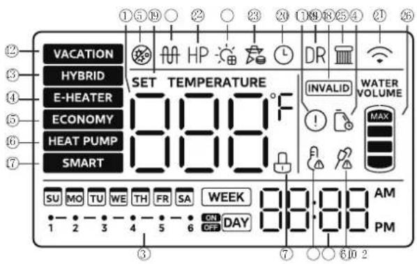
VACATION HYBRID E-HEATER ECONOMY HEAT PUMP SMART SET TEMPERATURE 000°F 1 2 3 4 5 6 7 8 9 10 11 12 13 14 15 16 17 INVALID WATER VOLUME MAX SU MO TU WE TH FR SA WEEK 00:00 AM 1 2 3 4 5 6 ON DAY 7 8 9 10 11 12 13 14 15 16 PM| No | Icon Description | |
| 1 | 888 ^r | 888will be lightened if screen is unlocked.It shows water temperature on normal;It shows remaining vacation days on vacation;It shows setting temperature on setting;It shows unit setting/running parameters,error/protection code on querying. |
| 2 | 20:08 | Time and clock setting20:08shows the clock.Whenever there is any setting for clock. |
| 3 | WEEKDAY | There are daily or weekly TIMER icon.If anyone of them has been set, this iconwill lighten the corresponding one when screen is unlocked;If there is none of timers has been set, it will keep extinguished.If timer is being set, this icon will flash the corresponding one with 2Hz frequency as well lighten the timer which has been set. |
| 4 | It flashes to remind the user to maintain the water tank. | |
| 5 | It will be lightened when the machine is disinfecting. | |
| 6 | Lock:If button is locked, the icon will be lightened,otherwise it will be extinguished. | |
| 7 | EVU:When the photovoltaic effective signal is detected,this icon lights up, this time the target temperatureof the machine is adjusted to the highest settemperature, and the machine makes hot waterquickly. | |
| 8 | E-heat:It will be lightened when E-heat is running, otherwiseit will be extinguished.NOTE: When the operating conditions are not metto turn on this function, the corresponding icon onthe wire controller lights up briefly and then goesout. | |
| 9 | High temp. AlarmIf water temp is higher than 50°C, it will be lightened,otherwise it will be extinguished. | |
| 10 | ! | Error:It will be lightened when unit is under protection/error. |
| 11 | VACATION | VACATION MODE:For the outgoing vacation mode, the water tank is set at 15°C. Maintains low tank water temperature, preheats hot water and anti-freeze lines, while reducing on/off operation of the tank. |
| 12 | HYBRID | HYBRID MODE:Operating in heat pump mode, the electric heater and heat pump will heat up together when in extremely low ambient temperatures or when the heat pump has been running for a long time without reaching the set Temp. Factory default mode setting, it is recommended to set this mode to run when heat recovery COOL+DHW. |
| 13 | E-MEATER | E-HEAT MODE:Operate in accordance with the heat pump mode, the heat pump outdoor unit and the electric heater running at the same time. |
| 14 | ECONOMY | ECONOMY MODE:In accordance with the heat pump mode of operation, the heat pump external unit heats up to the maximum water temperature before turning on the electric auxiliary heater for heating, the heat pump and the electric auxiliary heater will not be turned on at the same time.It is recommended to use this mode of operation when making hot water alone, which is more energy-saving.NOTE:Energy-saving mode to limit the start of electric heating, running more energy-saving, but do not recommend COOL + DHW use this mode, easy to affect the effect of hot water heating effect. |
| 15 | SMART | SMART MODE:Records the hot water usage habits of users over the past 7 days and turns on the heating in advance according to the user's peak water usage hours. All other unconventional hot water hours are in standby mode, without heating operation (it is recommended that users set this mode after 7 days of regular and normal operation of the water heater to avoid affecting the normal use of the water heater by failing to record the complete user habits.) |
| 16 | INVALID | When any key is invalid, this icon will flash 3 sec. |
| 17 | SET TEMP | The icon lights up when the water temperature is being set. |
| 18 | L | The icon lights up when the clock is being set. |
| 19 | Wireless:Will be lightened when Wireless is connected;will be extinguished when Wireless is not connected;will flash with 2Hz frequency when setting Wireless. | |
| 20 | HP | HEAT PUMP ICON:When the heat pump is operating and producing hot water, the icon lights up. |
| 21 | Smart Grid ICON:When the SG signal is invalid, this icon does not light up and the machine does not switch on normally. |
text_image
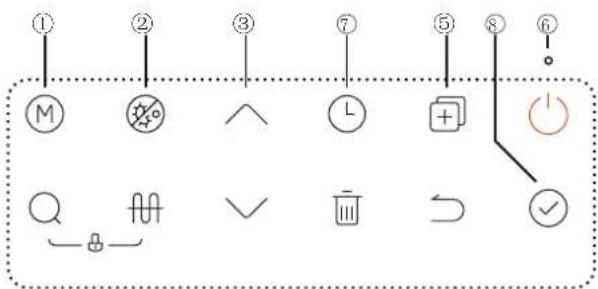
Diagram showing a sequence of labeled icons and symbols, including M, checkmark, up/down, L, plus, power button, and checkmark.Any pressing of button is effective only under button and display unlocked state.
| No. | Icon Description |
| 1 | M |
| 2 |
| No | con Description | |
| 3 | INCREASE AND DECREASEIf screen is unlocked, corresponding value will increase by pressing the button.When setting temperature, press more than 1s, temperature value will be increased continuously;When setting clock/timer, press more than 1s, clock/timer value will be increased continuously;When setting vacation days, press more than 1s, day value will be increased continuously;On querying, check items will page up by pressing it. | |
| 4 | Checking function1) In the main interface, press and hold the search key for 1 second to enter the spot check function, and use the up and down keys to switch the spot check channel, and the attribute value of the channel will be displayed when switching to the channel, and the specific channel can be found in the function book.After 30 seconds from the last operation of the up and down keys, or by pressing the return key or the on/off key, you can directly exit the engineering mode;Query mode can be entered in both power-on and power-off state. | |
| 5 | Engineering Mode1) In the main interface, press and hold the copy key for 3 seconds to enter the engineering mode; use the up and down keys to switch the inspection channel, and the attribute value of the channel will be displayed when switching to the channel. By up and down key, you can modify a parameter setting, after setting and adjusting, press confirm key to return to the main interface to make the setting effective (channel 2, 3, 4, 34, 35 will be effective immediately). Press the Return button to return to the previous interface (channel selection interface). After 30 seconds from the last operation of the up and down buttons, or by pressing the return button or the on/off button, you can directly exit the engineering mode.Engineering mode can be accessed in both power-on and power-off state.F13 - Priority settings for Heating (AC) and Hot water production (DHW)Parameter 0: Air conditioning is prioritized;Parameter 1: Hot water priority;The factory default setting is air conditioning priority, during engineering installation, it is necessary to confirm its priority selection settings with the customer and guide the instructions for use.It is strictly prohibited for the customer to change the parameter settings of other channels in the engineering mode without authorisation to avoid affecting the normal operation of the unit or causing damage to the prototype. | |
| 6 | Power on/off buttonPress the button to turn the device on or off. |
| No | Icon Description |
| 7 | L |
5.3 Combination button
| No. | Icon | Description |
| Setting the date and clock | 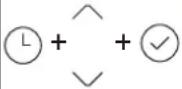 | 1) In the main interface, press and hold the timer button for 3 seconds to enter the date setting, press the up/down button to select the date, press the confirmation button to enter the clock setting, press the up/down button to modify the time, and press and hold to accelerate the increase/decrease of the time. After setting the clock, press the confirm button to return to the main interface to complete the setting of date and time.(2) After 30 seconds from the last operation of the up/down button or pressing the return button or the power on/off button, you can directly exit the date and time setting;3) Setting can be done in both power-on and power-off state. |
| connecting the wireless function |  Press for 3 sec Press for 3 sec | 1) In the main interface, long press the on/off key for 3 seconds to enter the AP wireless network mode, there will be a wireless icon in the upper right corner of the line controller. At this time, enter the APP, select the category of air water heater, choose the correct model, and then network according to the APP prompts, and after the network is completed, the wireless icon will be always on;(2) Wireless matching can last up to 8 minutes, after 8 minutes, if the matching is not successful, the wireless icon will go out;3) Long press the delete button for 8 seconds in the main interface to reset the wireless function;4) It can be set in both power on and power off state.NOTE: Please check the 5.4 Using the SmartHome App for details. |
| Child lock function | 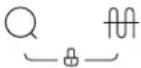 Press for 2 sec Press for 2 sec | 1) In the main interface, long press the key combination for 2 seconds to enter the child lock state;(2) In the state of child lock, long press the key combination again for 2 seconds to release the child lock state;3) In the locked state, there will be an icon next to the water temperature display. |
5.4 Priority schedule

NOTE
If the booster heater always takes over the DHW heat load due to setting Priority schedule to AC, electricity consumption will be considerably higher. For the months where space heating/cooling is less important, it is recommended to set the Priority schedule to DHW.
If DHW is set as priority and frequent DHW operation is expected, there is risk for comfort problem due to interruption of AC operation. For the months where space heating/cooling is more important, it is recommended to set the Priority schedule to AC.
Air Conditioning or domestic hot water priority
When multiple indoor units are connected to the outdoor unit (refer to Installer Reference Guide for details), the user can set on the user interface whether to put DHw or Air Conditioning (A/C) as priority. This will determine how the outdoor unit will react in case multiple indoor units requested operation at the same time:
- If DHW is set as priority, outdoor unit can decide to operate only for DHW, while A/C operation is put on hold. In this case, once DHW operation is finished, outdoor unit can switch to A/C operation.
- If A/C is set as priority, outdoor unit can decide to operate only A/C, in which case booster heater can start for DHW production. Once A/C operation is finished, outdoor unit can switch to DHW.
To select the Priority schedule
| 1 | Click + to enter engineering mode and select F13 channel. | Press the up and down keys to operate |
| 2 | Select air conditioning mode priority, F13 set to 0. | Press the up and down keys to operateConfirm |
| 3 | Select hot water making mode priority, F13 set to 1. | Press the up and down keys to operateConfirm |
5.5 Using the SmartHome App

NOTE
Ensure that your mobile phone is connected to the wireless network. Bluetooth must be turned on. The device must also be powered up.
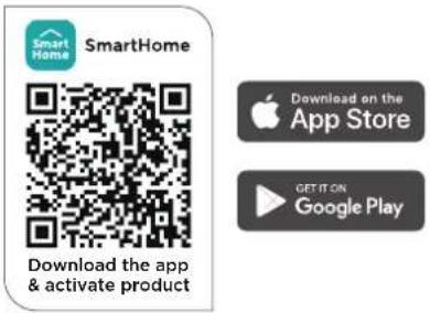
■ Step 1: Download the SmartHome app
Scan the QR code below to download the SmartHome app from app store or search for it directly on the Google Play Store or Apple's App Store.
text_image
SmartHome SmartHome Download the app & activate product Download on the App Store GET IT ON Google Play■ Step 2: Log in
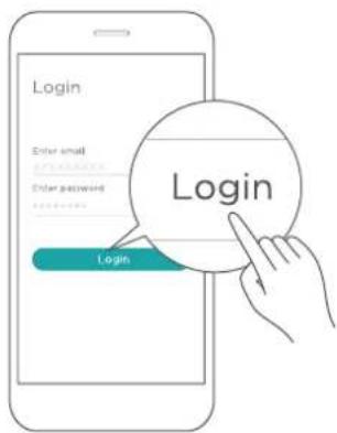
Open the SmartHome app. Log in directly if you have an existing SmartHome account or create a new account. Alternatively, you can also use a 3rd party login platform.
text_image
Login Enter email Enter password Login Login■ Step 3: Connecting the device
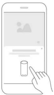
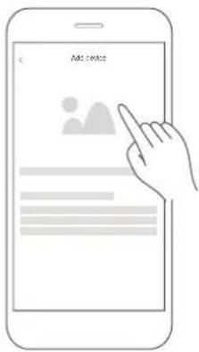
1) When you log in, you may see the message "Smart devices discovered nearby". Tap to add your device.
natural_image
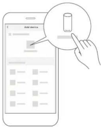
Illustration of a hand interacting with a smartphone displaying a screen interface (no text or symbols visible)2) If no such message appears, proceed as follows: Tap on "+" and select your device in the list of nearby available devices.
If your device is not listed, please add your device manually, first selecting the device category e.g. Water Heater.
text_image
Add device3) Follow the steps in the app to connect your device to the wireless network. If your device fails to connect, follow the additional instructions in the app.
text_image
Add content■ Step 4: Controlling the device
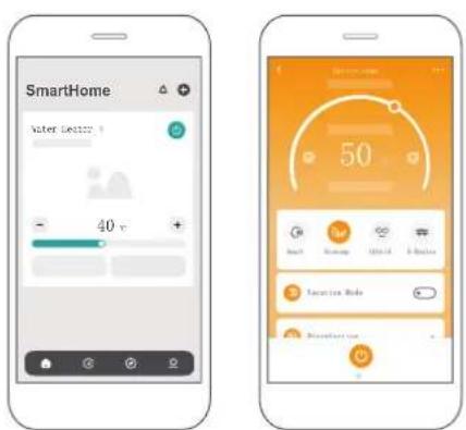
After pairing successfully, a card will be created for the device in the SmartHome app.
Shortcuts for basic functions will appear on the card such as changing the temperature or switching the device on or off.
Tapping on the card, will reveal additional features and settings. The actual UI design may look different from examples due to app updates.
text_image
SmartHome 50 40 v 50 Service Tools5.5 Compliance
We, hereby declare that this device is in compliance with the relevant provisions of RE Directive 2014/53/EU. A copy of the full DoC is attached (Europen Union products only).
Wireless module models:
This device complies with Part 15 of the FCC Rules and it contains licence exempt transmitter(s) / receiver(s) that comply with Innovation, Science and Economic
Development Canada's licence-exempt RSS(s).
Operation is subject to the following two conditions:
(1) This device may not cause harmful interference;
(2) This device must accept any interference, including interference that may cause undesired operation of the device.
Only operate the device in accordance with the instructions supplied.
Changes or modifications to this unit not expressly approved by the party responsible for compliance could void the user's authority to operate the equipment.
This device complies with FCC radiation exposure limits set forth for an uncontrolled environment. In order to avoid the possibility of exceeding the FCC radio frequency exposure limits, human proximity to the antenna shall not be less than 20cm (8 inches) during normal operation.
In Canada:
CAN ICES-3(B)/NMB-3(B)
This equipment has been tested and found to comply with the limits for a Class B digital device, pursuant to part 15 of the FCC Rules. These limits are designed to provide reasonable protection against harmful interference in a residential installation. This equipment generates, uses and can radiate radio frequency energy and, if not installed and used in accordance with the instructions, may cause harmful interference to radio communications. However, there is no guarantee that interference will not occur in a particular installation. If this equipment does cause harmful interference to radio or television reception, which can be determined by turning the equipment off and on, the user is encouraged to try to correct the interference by one or more of the following measures:
- Reorient or relocate the receiving antenna.
- Connect the equipment into an outlet on a circuit different from that to which the receiver is connected.
- Consult the dealer or an experienced radio/TV technician for help.
5.6 Auto-restart
If electricity power failed, unit can memorize all setting parameters, unit will be back to the previous setting when power recover.
5.7 Button Auto Lock
When there is no operation of button for 1 minute, button will be locked except Unlock button Ⓠ + ⏻ for 2s, unlock buttons.
5.8 Screen Auto Lock
If there is no operation of button for 60s, screen will be locked (extinguished) except for error code and alarm icon. Press any button will unlock the screen(lighten). Enter engineering mode 35 channel enable this function.
6. TROUBLE SHOOTING
6.1 Non-error tips
Q: Why compressor can't start immediately after setting?
A: Unit will wait for 3 minutes to balance the pressure of system before starting compressor again, it's a self protection logic of unit.
Q: Why sometimes the temperature shown on the display panel decreased while unit is running?
A: When the upper tank temperature is much higher than the bottom part, upper part hot water will be mixed by the bottom cold water which is continually flow from inlet tap water so that will decrease the upper part temperature.
Q: Why sometimes the temperature shown on the display decreased but unit still keep closed?
A: To avoid unit ON/OFF frequently, unit will activate heat source only when bottom tank temperature is lower than setting temperature or max. temperature for at least 6 °C.
Q: Why sometimes the temperature shown on the display will decreased dramatically?
A: Because tank is pressure-bearable type, if there is massive hot demand, hot water will quickly tapped out from upper part of tank as well as cold water will quickly tapped into bottom part of bank if the cold water surface emerge the upper temperature sensor, temperature shown on the display will decreased dramatically.
Q: Why sometimes the temperature shown on the display is decreased a lot, but there is still a mount of hot water can be tapped?
A: Because the upper water sensor is located on the upper 1/4 tank, when display temperature starts falling down quickly, it means there is at least 1/4 tank of hot water available.
Q: Why sometimes the buttons are unavailable?
A: If there is no operation on panel for 1 min, unit will lock the panel, shows "☐", to unlock the panel, please press the "Q" button for 2 seconds.
Q: Why sometimes there is some water flowed from drainage pipe of PTR valve?
A: Because the tank is pressure-bearable one, when water is heated inside the tank, water will expand, so the pressure inside of tank will increase, if pressure goes up more than 1.0MPa, PTR valve will activate to relief the pressure and hot water drop will be discharged correspondingly. If water drop is continually discharged from PTR valve drainage pipe, it is abnormal, please contact qualified stuff to repair.
6.2 Something about self-protection of unit
1) When the self-protection happens, the system will be stopped and start self-check, and restart when the protection resolved.
2) When the self-protection happens, the ⏻ will flash and error code will be shown at water temperature indicator. But the ⏻ and error code does not disappear until protection resolved.
In the following circumstance, self-protection may happen: Air inlet or outlet is blocked;
3) The evaporator is covered with too much dust; Incorrect power supply(exceeding the range of 220-240V).
6.3 When error happened
1) If some normal errors happen, unit will automatically shift to E-heater for emergent SHW supply, please contact qualified staff to repair.
2) If some sever errors happen, unit will not start, please contact qualified staff to repair.
6.4 Error phenomenon shooting
| Error phenomenon Possible reason & Solution | |
| Display does not light up/water is cold. | Check that the air switch is closed/set the temperature high. |
| No hot water coming out. | Check that the tap line is clear; check that the tap water pressure is not too low. |
| Water in safety valve relief port flow out of the pressure relief port of the safety valve. | If there is only a small amount of water flow out, for the water thermal expansion caused by the normal phenomenon, do not block; if a large amount of water flow out, please replace the safety valve. Please replace the safety valve. |
| It takes a long time to heat a tank of water. | When the ambient temperature is low, the heating speed of the unit is reduced, which is a normal phenomenon, please heat up in advance.Check whether the electric heating is running normally, check whether the set mode is air conditioning + hot water production at the same time on mode, at the same time on mode under the slower rate of warming. |
| Automatic operation or shutdown. Is it because the reservation/timer function is set. | |
| It do not work. | Is the air switch not closed. •Is the fuse blown. • Whether the reservation/timer function is set.Whether it is caused by the protection of the unit (the corresponding protection code will be displayed)Whether the water temperature is high and has not reached the conditions for the unit to turn on. |
| The heating effect is not obvious. Whether the air inlet and outlet of the unit are blocked. | |
| Compressor does not run after power on. | There is hot water in the tank and it can be used.When the power switch is turned on, the hot water dispenser will not run for about 3 minutes after the operation stops, because the compressor cannot be started within 3 minutes of stopping.The water heater cannot run for about 3 minutes after running stops when the power switch is turned on. |
| Display of water temperature Slow rise. | Because the upper part of the tank water temperature is higher, the middle and lower part of the water temperature is lower, need to wait until the whole tank water temperature is basically the same, show the water temperature will rise faster. When the temperature of the water in the whole tank is basically the same, the temperature of the water will rise faster. |
| Shows that the water temperature is heating decreases during the heating process. | When the temperature of the upper part of the tank is much higher than the lower part of the water temperature, due to the natural convection of hot and cold water in the heating process, it will make the Hot and cold water will be stirred and mixed to a certain extent, and the temperature of the upper hot water will be slightly reduced, or the unit may slightly reduce the temperature when the defrosting action is performed. The temperature of the upper hot water will be slightly reduced, or when the unit is defrosting, the display temperature may also be slightly reduced. |
| The water temperature is displayed as dropping. Low and no heating. | Due to natural heat dissipation, the temperature of the hot water in the tank will gradually decrease when it is not used for a long time. In order to avoid host too often turn on and stop, the host has made a provision for water temperature, non-water use, when the display of the water temperature is reduced by In case of non-water use, the heating of the mainframe will be turned on only when the water temperature is lower than the set return temperature (the return value can be set through the line controller). |
| The display shows that the water temperature will Suddenly, the water temperature will drop a lot. | Since the unit is built-in pressurized water tank, when using hot water, cold water needs to enter the tank to top off the hot water, and there will be obvious stratification between the hot and cold water. There will be obvious stratification between the hot and cold water, when the cold water overflows the temperature sensor on the upper part of the tank, the water temperature will be suddenly reduced. When the cold water overflows the temperature sensor on the upper part of the tank, the water temperature will be suddenly lowered, which is a natural phenomenon of the high utilization rate of the unit's water tank. |
| It shows that the temperature of the water is lowered a lot. But it's still hot water. | The upper part of the water tank temperature sensor is placed in the upper 1/4 of the water tank, and the display of the water temperature is the temperature of the upper part of the water tank temperature sensor. When the water is being used and the displayed water temperature is suddenly lowered, there is still almost 1/5 of the tank's hot water available for use. When the water is being used, there is still almost 1/5 tank of hot water in the tank after the display water temperature drops suddenly. |
| Displayed water temperature and set water temperature difference. | Whether to set the reservation function, the unit will be heated up in advance when reservation is made, and the display temperature will be slightly decreased due to natural heat dissipation, which is a normal phenomenon. Due to natural heat dissipation, the display temperature will drop slightly, which is a normal phenomenon.Whether the unit is protected. |
| During the heating process the compressor will not stop running and the fan machine stops. | When the ambient temperature is low, the evaporator may be frosted resulting in poor heat transfer, at this time the host will be defrosting operation. The compressor will be running when defrosting, and the fan will stop running. |
| Safety valve running water. | As the water tank itself is a closed pressurized container, when heated, the water is subjected to thermal expansion. When the pressure inside the tank is greater than 0.85MPa, the pressure relief port of the safety valve will act to flow out hot water, thus protecting the tank from pressure damage or even explosion. |
| Deviation of display from set temperature. | When the unit reaches the temperature and stops, there may be a small deviation between the display temperature and the set temperature, which is a normal phenomenon. |
| Reaching the temperature stopping hot water is not enough. | The use of the process in the set temperature is low, up to temperature shutdown after the display of the amount of water may not be full grid, is a normal phenomenon, the unit can provide a certain amount of hot water to use, if the user demand for hot water is more, it is recommended to raise the set temperature. |
| The unit heats up for a period of time and shows that the temperature has not risen. | In the process of use, the unit heats up when the water tank shows that the water temperature has not risen, you can pay attention to the amount of hot water to show whether the number of grids increased, if the increase is due to the lower part of the more cold water into the unit mainly heats up the water temperature in the lower part of the water temperature, the priority of the water tank under the temperature rise and the upper part of the water tank does not have a significant increase in the phenomenon is normal. |
| Displayed temperature after sterilization Deviation from set temperature | Sterilization is completed after a period of time, the current display temperature and the user set temperature is not consistent with the normal phenomenon. It takes a long time for the water tank temperature to decrease from 70°C to the user setting temperature;Turn on the forced sterilization or automatic sterilization, the set temperature of the unit becomes 70°C (once effective). The sterilization symbol of the heating process lights up. After the water tank temperature reaches 70°C to complete the sterilization, the sterilization icon goes out. |
6.5 Error code shooting table
| Display | Malfunction Description |
| Tank and LCD panel communication error. | |
| Machine working parameters are abnormal. | |
| EL01 | Faulty communication between water tank and outdoor unit |
| Leakage protection | |
| EC54 | Error of TP |
| Error of T4 | |
| EC52 | Error of T3 |
| EH5L | Error of T5L |
| EH5U | Error of T5U |
| EH5d | Electric heating disconnection protection |
| Dry burning protection | |
| Abnormal operating parameters of the outdoor unit | |
| Anti-freeze protection for refrigeration status | |
| Anti-freeze protection for low-temperature conditions | |
| DC fan out of phase | |
| PC12 341 V | Voltage protection or MCE fault |
| Display | Malfunction Description |
| PC00 IPM module protection | |
| PC01 Main control voltage protection | |
| PC02 Compressor top temperature protection | |
| PC03 System pressure protection or failure | |
| PC04 | Compressor feedback protection |
| PC08 Outdoor unit current protection | |
| PC40 Outdoor main control & driver chip communication failure | |
| PC43 Compressor phase failure protection | |
| PC44 | Compressor 0 speed protection |
| PC45 341PWM Synchronization Guarantee | |
| Compressor stall protection | |
| Compressor overcurrent protection | |
| PC51 | T2 high temperature protection |
| PC52 | T2 low temperature protection |
| EC07 Outdoor unit fan stall protection | |
| PH9b | Over-temperature protection for water tanksIGBT sensor failure |
| T2b sensor failure |

NOTE
- The diagnostic codes listed above are the most common. If a diagnostic code not listed above is displayed, contact residential technical assistance referenceing the number on the front of this manual.
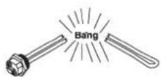
- Open the drainage valve, and drain out the water, until there are no water flow out.
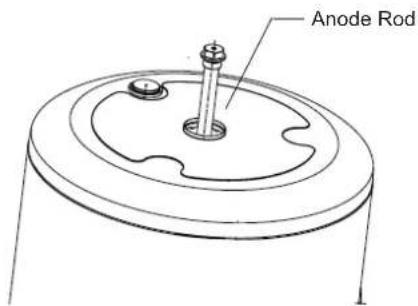
- Get off the anode rod.
- Replace with a new one, and make sure effective sealed.
- Open cold water inlet tap until water flows out from outlet tap, then turn of water outlet tap.
• Power on then restart the unit.
NOTE:
- As the Anode Rod needs to be replaced from the top, a minimum height of 800mm needs to be left at the top of the installation to allow for the replacement of the Anode Rod.
- Replacement of Anode Rods should be carried out by a professional service technician, do not replace Anode Rods without authorization as this may damage the tank.
text_image
Anode Rod7. MAINTENANCE

CAUTION
The maintenance of the unit requires professional after-sales personnel responsible for overhauling the unit.
7.1 Maintenance
1) Check the connection between power supply plug and socket and ground wiring regularly;
2) In some cold area (below 0^ C), if the system will be stopped for a long time, all the water should be released in case of freezing of inner tank and damage of E-heater.
3) It is recommended to clean the inner tank and E-heater every half year to keep an efficient performance.
4) Check the anode rod every half year and change it, if it has been used out. For more details, please contact the supplier or the after-sale service.
5) It is recommended to set a lower temperature to decrease the heat release, prevent scale and save energy if the outlet water volume is sufficient.
6) Clean the air filter every month in case of any inefficiency on the heating performance.
In terms of the filter set in air inlet directly (namely, air inlet without connect with duct), the method of dismantle the filter is: anti-clockwise unscrew the air inlet ring, take out the filter and clean it completely, finally, remount it to the unit.
7) Before shutting the system off for a long time, please:
Shut off the power supply;
Release all the water in water tank and the pipeline and close all the valves;
Check the inner components regularly.
8) How to change the anode rod
• Turn off the power, and turn off the water inlet valve.
- Open hot water tap, and decrease the pressure of the inner container.

WARNING
- Battery must be disposed of properly. Do not short circuit or dispose of in the fire.
- Keep batteries out of the reach of children.
- Caution for ingestion.
- Non-rechargeable batteries are not to be recharged.
- Exhausted batteries are to be removed from the product.
- Dispose of the old batteries in the special containers to be found in the sales outlets.
- Replace the battery must contact the supplier or the after-sale service.
7.2 Recommended regular maintenance table
| Checking Item | Checking content | Checking frequency | Action |
| 1 | air filter (inlet/outlet) | every month Clean the filter | |
| 2 | anode rod every half year | Replace it if it has been used out | |
| 3 | inner tank every half year Clean the tank | ||
| 4 | E-heater every half year Clean E-heater | ||
| 5 | PTR valve | every year | Operate the hander of PTR valve to ensure that waterways are clear. |
| If water doesn't flow freely when operating the hander, replace PTR valve with a new one. | |||
SR24
HTW-DI-8SR24R32A
natural_image
White cylindrical water heater unit with 'HTW' label and digital display (no visible text or symbols on body)FRANÇAIS
natural_image
Pure electrical circuit symbol for a diode (no text or labels)natural_image
Blue circular icon with white pictogram showing a adult and child interacting (no text or symbols)natural_image
Technical line drawing of two rectangular electronic devices labeled A and B, with internal components and height dimension H (no text or symbols beyond labels)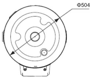
text_image
Φ504text_image
VACATION HP DR HYBRID SET TEMPERATURE INVALID WATER VOLUME E-HEATER ECONOMY HEAT PUMP SMART SU MO TU WE TH FR SA WEEK 00:00 AM 1 2 3 4 5 6 DAY PM Affichage Operationtext_image
Diagram showing labeled icons and symbols with numbered labels, likely representing a control or logic layout.natural_image
Illustration of a hand interacting with a smartphone displaying a simple UI element (no text or symbols visible)text_image
Add devicetext_image
SmartHome Water Heater 40% Balance every 50% Snow, Drying, Hide, Smoke Variation Mode Discharge5.5 Conformité
natural_image
Exterior view of a white cylindrical water heater unit (no visible text or symbols)PORTUGÊS
natural_image
Pure electrical circuit symbol for a diode (no text or labels)natural_image
Blue circular icon with white pictogram showing a adult and child interacting (no text or symbols)natural_image
Technical line drawing of a vertical rectangular device with a small inset panel, shown in two-dimensional perspective (no text or symbols)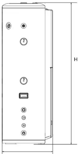
natural_image
Technical line drawing of a vertical cylindrical device with multiple buttons and a labeled height dimension (no text or symbols beyond basic geometry)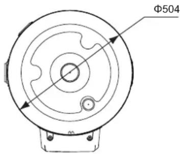
text_image
Φ504natural_image
Illustration of a hand interacting with a smartphone displaying a user profile interface (no text or symbols on screen)text_image
Add devicetext_image
Add orders■ Passo 4: Controlar o dispositivo
text_image
SmartHome Water Heater 40% Balance every 50% Snow, Weather, Solar, Weather Variation Mode Disinforcement5.5 Cumprimento
natural_image
White cylindrical water heater unit with digital display and control buttons (no visible text or symbols)ITALIANO
natural_image
Pure electrical circuit symbol for a diode (no text or labels)natural_image
Blue circular icon with white human and child silhouettes, no text or symbols presentnatural_image
Technical line drawing of a vertical rectangular device with a small inset panel, shown in two-dimensional perspective (no text or symbols)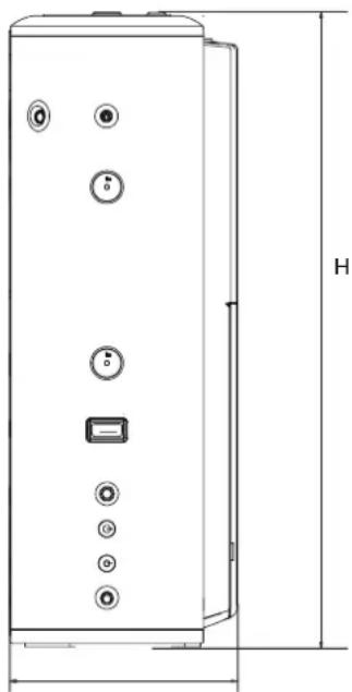
natural_image
Technical line drawing of a vertical cylindrical device with multiple buttons and a labeled height dimension (no text or symbols beyond basic geometry)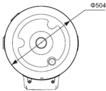
text_image
Φ504text_image
Diagram showing labeled icons and symbols, including circles, arrows, and checkmarks with corresponding labels like M, L, +, -, √, and a power button.natural_image
Illustration of a hand interacting with a smartphone displaying a user profile interface (no text or symbols on screen)text_image
Add devicetext_image
Balance mmH 50°C Smart Battery Hotel Radio Variation Mode Distribution on5.5 Cumplimiento
RED Declaration of Conformity (DoC)
Unique identification of this DoC: 31032023
We, Gestion Integral de Almacenes S.L declare under our sole responsibility that the product:
product name: Smart Kit
trade name: HTW
type or model: EU-OSK105
relevant supplementary information: 8435483801844
(e.g. lot, batch or serial number, sources and numbers of items)
to which this declaration relates is in conformity with the essential requirements and other relevant requirements of the RE Directive (2014/53/EU).
The product is in conformity with the following standards and/or other normative documents:
HEALTH & SAFETY (Art. 3(1)(a)): EN IEC 62311:2020, EN 50665:2017, EN 62368-1:2014/A11:2017
EMC (Art. 3(1)(b)): EN 301 489-1 V2.2.3: 2019, EN 301 489-17 V3.2.4 :2020
SPECTRUM (Art. 3(2)): EN 300 328 V2.2.2 :2019
OTHER (incl. Art. 3(3) and voluntary specs):
(title and/or number and date of issue of the standard(s) or other normative document(s))
Limitation of validity (if any):
Supplementary information:
Notified body involved: N/A
Technical file held by: GESTION INTEGRAL DE ALMACENES S.L
Place and date of issue (of this DoC): Barcelona/2023-04-04
Signed by or for the manufacturer:
(Signature of authorised person)
Name (in print): FRANCISCO SANZ CASTRO
Title: FOUNDER / CEO
GIAGroup
C. Can Cabanyes, 88 08403 Granollers
(Barcelona) - España tel. +34 93 390 42 20
info@htwspain.com
www.htwspain.com

España info@htwspain.com | France info@htwfrance.com
Portugal info@htw.pt | Italy info.it@htwspain.com
SAT

España sat@groupgia.com
France sat.fr@groupgia.com
Portugal sat.pt@groupgia.com
Italy sat.it@groupgia.com
tel.+34 933904220
tel.+33 465430168
tel. +39 05641715509

At the end of its working life, the product must not be disposed of as urban waste. It must be taken to a special local authority deifferentiated waste collection centre or to a dealer providing this service. Disposing of a household appliance separately avoids possible negative consequences for the environment and health deriving from inappropriate disposal and enables the constituent materials to be recovered to obtain significant savings in energy and resources. As a reminder of the need to dispose of household appliances separately, the product is marked with a crossed-outwheeled dustbin.
AVERTISSEMENTS POUR L'ÉLIMINATION CORRECTE DU PRODUIT AUX TERMES DE LA DIRECTIVE 2002/96 / CE.