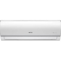
EON - Air Conditioning HTW - Free user manual and instructions
Find the device manual for free EON HTW in PDF.


User questions about EON HTW
0 question about this device. Answer the ones you know or ask your own.
Ask a new question about this device
Download the instructions for your Air Conditioning in PDF format for free! Find your manual EON - HTW and take your electronic device back in hand. On this page are published all the documents necessary for the use of your device. EON by HTW.
USER MANUAL EON HTW
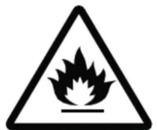
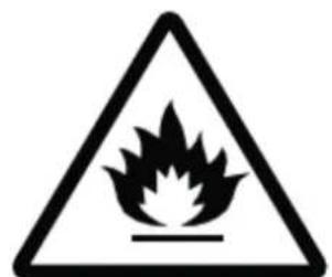
Caution, risk of fire
8.1 DESCARGAR E INSTALAR LA APP


GIApp
PARA ANDROID
Owner's and installation manual. Split 1x1
TABLE CONTENT
01 SECURITY INSTRUCTIONS 44
1.1 Symbol Description 44
1.2 Installation instructions 44
1.3 Operating instructions 44
1.4 Security instructions 45
02 PRODUCT PRESENTATION 47
2.1 Protection functions 47
03 COMPONENT DESCRIPTION 48
3.1 Unit view 48
3.2 Screen display 49
3.3 Indicators 49
3.4 Remote control 50
3.5 Remote control display 51
4.1 Emergency functions 52
4.2 Air flow regulation 52
4.3 Energy saving Sleep function 53
05 MAINTENANCE 54
5.1 Cleaning the front panel and remote control ... 54
5.2 Filter cleaning 54
5.3 Maintenance when not in use for a long time.. 55
5.4 Energy saving 56
06 TROUBLESHOOTING 57
6.1 Air conditioning errors 57
6.2 Remote control errors 57
6.3 Error codes 58
07 INSTALLATION 59
7.1Foreword 59
7.2 Installation Guide 60
7.3 Position for Indoor Unit 60
7.4 Position for Outdoor Unit 61
7.5 Tubing Selection 61
7.6 Fixing installation panel 62
7.7 Indoor unit installation 63
7.8 Outdoor unit installation 64
7.9 Tubing connection 65
7.10 Wire connection 66
7.11 Tube strapping 67
7.12 Exhaust 68
7.13 Gas leakage inspection 68
7.14 Drainage 69
7.15 Installation for the cover of valve 69
08 WIFI SETUP 70
8.1 Download and install the app 70
8.2 Sign up 71
8.3 Log in 72
8.4 Add a device 72
8.5 Notices 76
- This manual is property of GIAgroup.
Copying or reproduction without prior permission is strictly prohibited.
1.1 SYMBOL DESCRIPTION

CAUTION: harm to the person.

ATTENTION: material damage.
1.2 INSTALLATION INSTRUCTIONS

CAUTION
shock, or fire.
Don't ride it alone:
The air conditioner will work for a long time if it is installed correctly. Incorrect installation may cause problems such as water or refrigerant leakage, electric

ATTENTION
Confirm the following before installation:
Power specifications
Make sure the switch outlet and power cord have sufficient capacity, the voltage is correct, and the outlet or switch is grounded. Otherwise, there may be a risk of fire or electric shock.
Installation environment
Do not install the air conditioner in places where there are flammable corrosive liquids.
- Correct connection of cables and pipes
Incorrect connection may decrease efficiency or cause the air conditioner to shut down. There may be a refrigerant or water leak.
-Operating instructions
Please use the air conditioner in accordance with this manual.
1.3 OPERATING INSTRUCTIONS
It is necessary to use single-phase voltage 220V - 50Hz
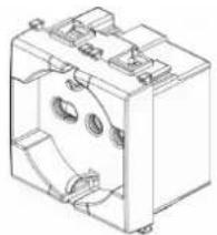
Use the specified power cord; don't change it.
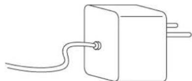
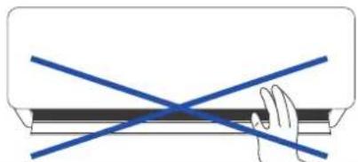
Do not insert fingers or sticks into the air conditioner inlet and outlet; the fan in operation can cause injury.
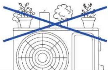
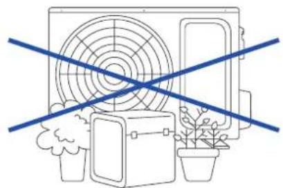
Do not place anything on the outdoor unit.
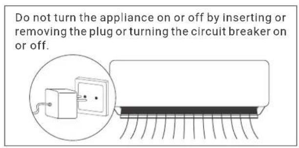
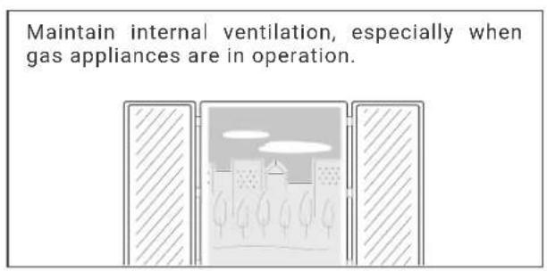
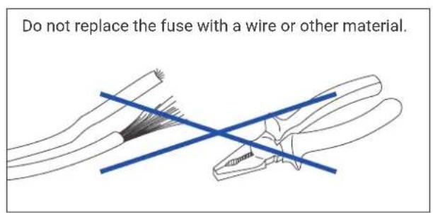
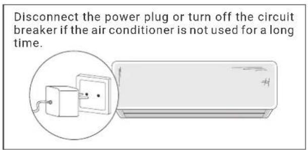
1.4 SECURITY INSTRUCTIONS
The appliance is not designed to be used by young children or the disabled without supervision. Young children should be supervised to ensure that they do not play with the device. If the power cord is damaged, it must be replaced by the
manufacturer or its technical service or by a similarly qualified person to avoid any risk.
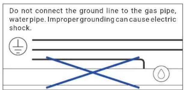
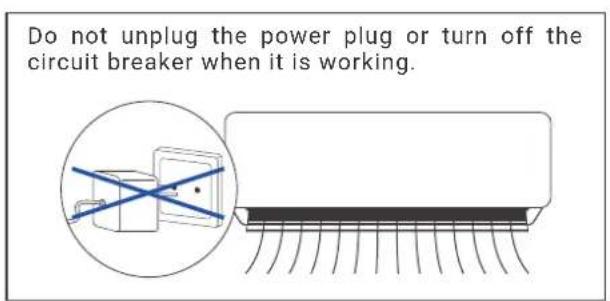
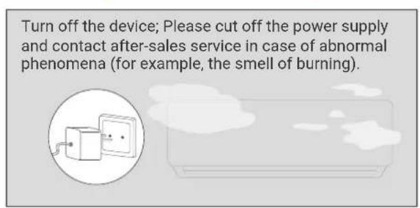
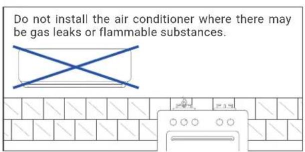
1. SECURITY INSTRUCTIONS
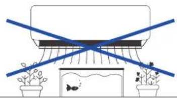
Do not place plants or animals directly in the airflow path of the air conditioner. I could hurt them.
Turn off the device, unplug the power, and make sure the fan stops before cleaning the device.
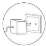
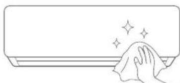
Contact your authorized service center for help. Improper maintenance can cause accidents.

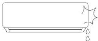
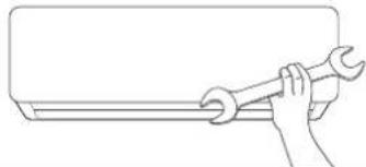
For the removal and installation of the air conditioner, please consult professionals or contact the after-sales service.

2.1 PROTECTION FUNCTIONS
Protection functions can extend the life of the air conditioner and provide more comfortable airflow.
- Delayed start protection for the compressor
The compressor will start to work at least 3 minutes (5 minutes in heating mode) after it stops to maintain the pressure balance of the refrigeration system.
- Observations
It will take 1 minute for the compressor to run after the unit is turned on for the first time.
Defrost
The outdoor heat exchanger may freeze if the outdoor temperature is low and the humidity is high. In this case, the automatic defrost will work for 3-10 minutes. The pause indicator will be on and the indoor and outdoor fans will not work.
-
HEAT overload protection (not available for cooling-only type of air conditioner) When the indoor pipe temperature is too high, the air conditioner enters heating overload protection mode, and the indoor fan speed should be set to a higher speed automatically. The outdoor fan and compressor can be stopped. When the indoor pipe temperature drops to a nominal value, the air conditioner exits overload protection mode. The indoor fan motor returns to its normal state.
-
Residual heat function not available for refrigeration - refrigeration type only) The indoor fan keeps running at low speed for 80 seconds when the air conditioner stops in heating mode.
-
Airflow Cooling Test (not available due to the raffreddamento - only of the type of conditioned air) In the first minutes of heating operation, the PAUSE light will come on; the internal fan does not work and the flaps cannot be controlled. Approximately 5 minutes later, the air conditioner emits a stream of hot air, the PAUSE light is off.
- Avoid freezing
In order to prevent the indoor heat exchanger from freezing during cooling and drying, the compressor or outdoor fan may stop working; the indoor fan speed will automatically adjust to a higher speed.
- Auto reset (optional)
The unit memorizes the operating mode, airflow setting, temperature setting, etc., so that if there is a power outage when the unit is running, it will automatically return to the same operating condition when it is restored energy.
- Anti drip
During cooling and dehumidifying operations, the louver flaps can automatically change position to prevent dripping.
3.1 UNIT VIEW
Indoor unit
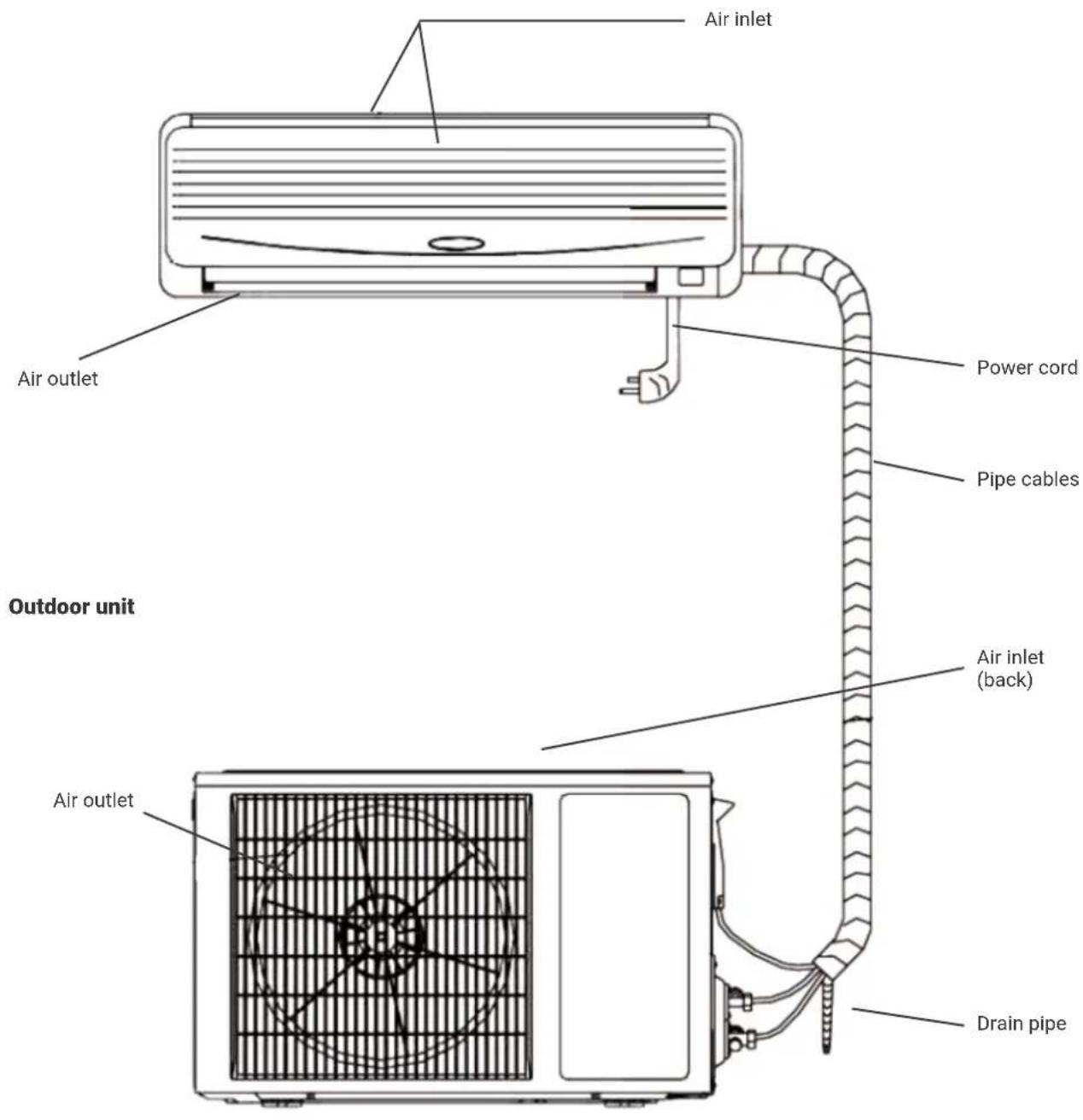
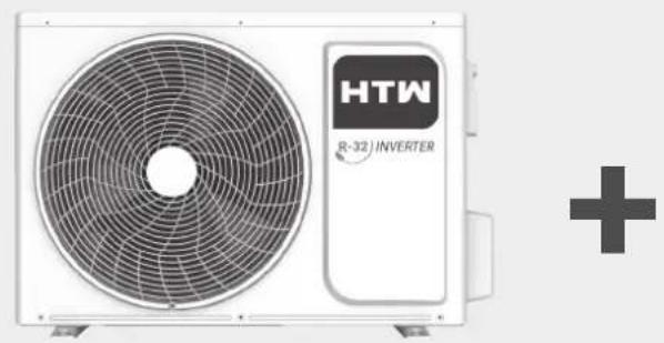
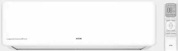
Note: The air conditioner consists of an indoor unit, an outdoor unit and a remote control. The design and shape are different for different models. The above diagram is just a drawing and may differ slightly from the actual device.
3.2 SCREEN DISPLAY

Health indicator:
This light is on when the UVC function or the Cold Plasma generator is working.

Timer indicator:
This signal light is on when the unit is in timer.

Compressor indicator:
This signal light is on when the compressor is running.

WiFi indicator:
Flashing on behalf of searching, lighting on behalf of WiFi completed connection, which means WiFi function can be operated and applicated (for more details, please refer to the WiFi instruction manual).

Temperature indicator:
This display can show the set temperature, when the indicator displays F4, F1 or F2, means the air conditioner runs abnormally.
(The above LED display is for reference only, subject to the actual product).
3.3 INDICATORS
1 "PAUSE"indicator
This indicator illuminates red when the air conditioner is in defrost or draft-proof cooling mode.
② "RUN" indicator
This indicator lights green when the unit is in "RUN" mode;
③ "TIMER" indicator
This indicator lights yellow when the unit is in TIMER mode.
④ "AIR REFRESH" indicator (optional)
This indicator lights green when the device is in AIR REFRESH mode and does not light if the device does not have an AIR REFRESH function.
5 "RECEIVER"indicator
Receives the signal from the remote control.
Note: If any of the "RUNNING", "PAUSE" or "TIMER" lights are blinking, contact Technical Services immediately.
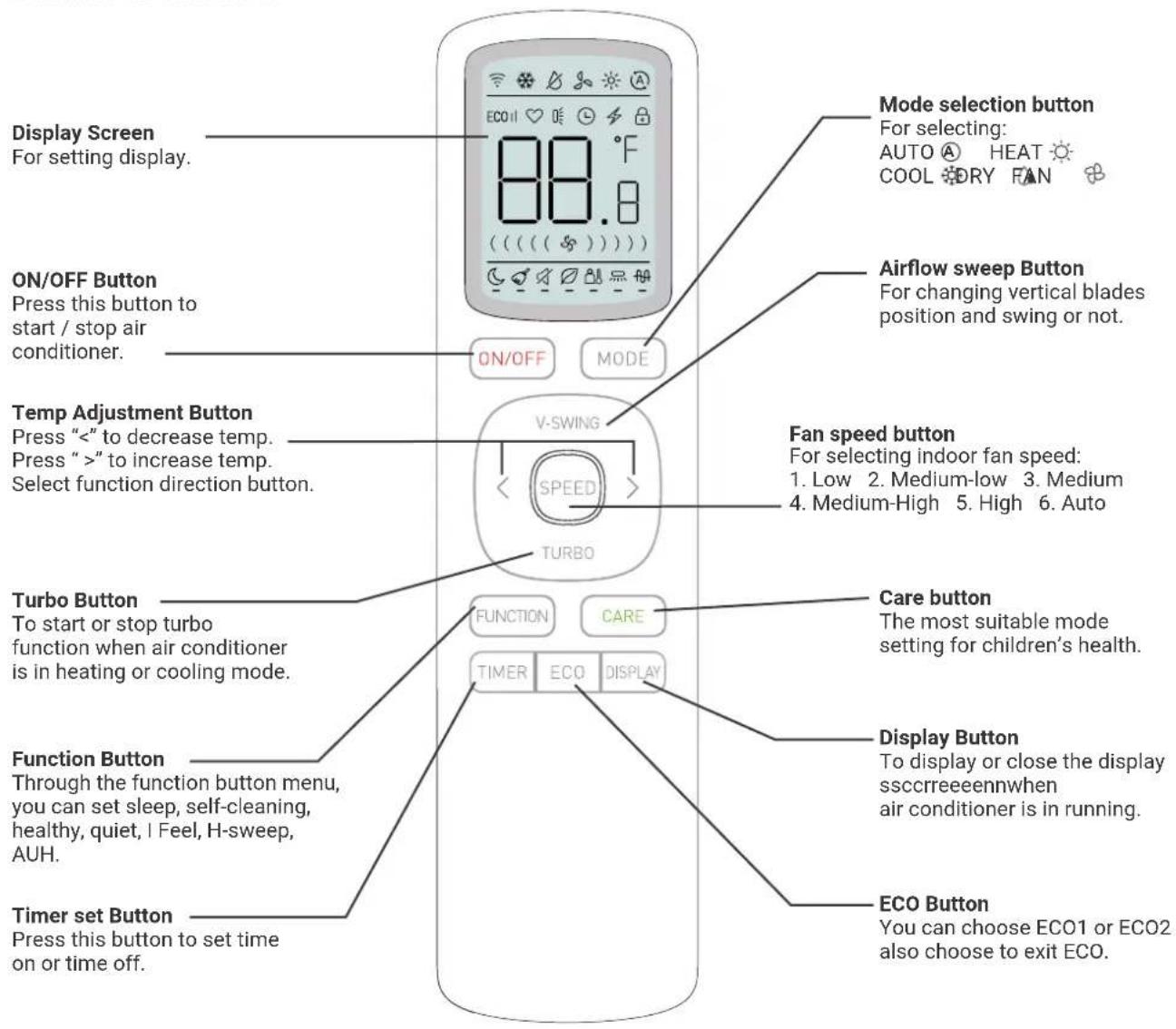
3.4 REMOTE CONTROL
Remarks:
- If user want to make the room air cool or warm quickly, user can press "turbo" button incooling or heating mode, air conditioner will run in power function.If press "turbo" button again, air conditioner will exit power function.
- Select function: enter the function menu, and press the add-subtract button to move back and forth to select the corresponding function. The selected function item flashes.
- Click the function button to first return to the next function position of the last set function. You can move the position of the function to be set by adding and subtracting keys. The function to be set flashes for 10s. Click the function key within 10s, and this function will be selected. The lower horizontal line of the selected function icon lights up. Click the function button again to cancel the function, and the lower horizontal line will cancel.
- Press and hold the "Temperature Up" and "Temperature Down" keys for 5S after turning on the machine, and the display can be switched to Fahrenheit. Press and hold the "Temperature Up" and "Temperature Down" keys for 5S again to switch back to Celsius.
- The above illustration of remote controller is only for reference, it may be slightly different from the actual product you selected.
3.5 REMOTE CONTROL DISPLAY
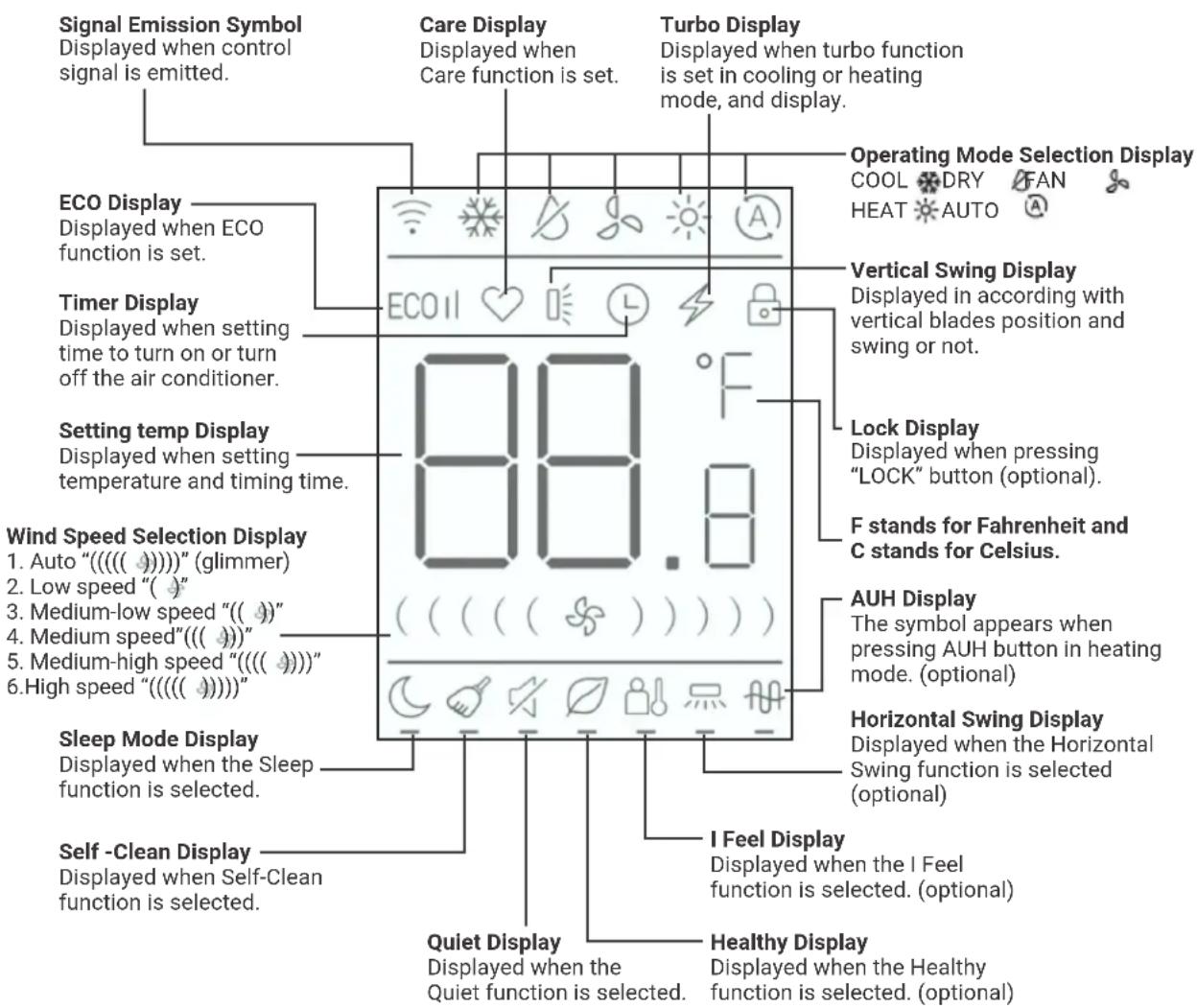
Instruction for remote controller
- The remote controller uses two AAA batteries under normal condition, the batteries last for about 6 months. Please use two new batteries of similar type (pay attention to the poles in installing).
- When using remote controller, please point the signal emitter towards indoor unit receiver. There should be no obstacle between remote controller and indoor unit.
- Do not use wireless equipment (such as mobile phone) near indoor unit. If interference occurs because of this, please switch off the unit, pull out power plug, then plug again and switch on after a while.
- There is no direct sunlight to the indoor receiver, or it can not receive the signal from the remote controller.
- Don't cast the remote controller.
- Don't put the remote controller under the sunlight or near the oven.
- Don't sprinkle water or juice on the remote controller, use soft cloth for cleaning if it occurs.
- The batteries must be removed from the appliance before it is scrapped and that they are disposed of safety.
4. OPERATION MODE
4.1 EMERGENCY FUNCTIONS
If you can't find the remote control or if the remote control batteries are dead, use the emergency switch.
4.2 AIR FLOW REGULATION
To start the airflow function.
Maneuver mode
-
When the air conditioner is off:
-
When the air conditioner is off, press the "AIR REFRESH" button, the air conditioner will turn on, press the SWEEP button, the "HEALTH" function will be activated.
- Pressing the "HEALTH" button again cancels the function,
-
By pressing the "HEALTH" button again, the air conditioner will be turned off,
-
When the air conditioner is working in "HEALTH" mode, if you press the "ON/OFF" button, you can change the mode (COOL, HEAT, etc.) while keeping the "HEALTH" function, the air conditioner will turn on. When the air conditioner is on, pressing the "HEALTH" button starts the cool air function..
Horizontal airflow adjustment
Use your hands to adjust the air outlet to adjust the flow to the right or left (Fig.5,6,1).
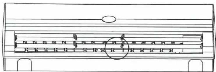
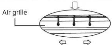
Fig.5.6.1
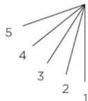
Fig.5.6.2

PRECAUCION
There's a fan inside, don't get your hands on it!
Vertical airflow adjustment
Repeatedly press the "SWEEP" button on the remote control, the flaps can be set to fixed position 1-5 (fig. 5.6.2) auto swing is activated in different modes, the flaps swing repeatedly in the defined range.
4.3 ENERGY SAVING SLEEP FUNCTION
When the air conditioner is on, press the "SLEEP" button to enter "SLEEP" mode on the remote control, this symbol will appear if you press the "SLEEP" button again, the icon will disappear and the sleep (energy saving) function will be cancelled.
- Function A: in standby mode, the set temperature will rise after 1 hour of operation in cool and dry mode; will decrease after 1 hour of operation in heating mode. The set temperature will be controlled between 16^ and 32^ . When the air conditioner is in SLEEP mode, the indoor fan speed is set to a medium level, but the user can change the fan speed with the remote controller.
- Function B: In standby mode, the set temperature and indoor fan speed will not change, but the display of the air conditioner will be off except for the "RUN" indicator.
5. MAINTENANCE
Careful maintenance and early inspection can extend the life of the air conditioner and reduce electricity bills.
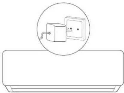
- Turn off the air conditioner with the remote controller and unplug it before performing service and maintenance.
- Do not stand on unstable objects when cleaning or maintaining the air conditioner, otherwise it may cause injury.
- Do not touch the metal part of the air conditioner body when removing the front panel, otherwise it may cause injury.
5.1 CLEANING THE FRONT PANEL AND REMOTE CONTROL
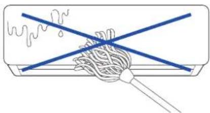
If the dirt cannot be removed, wipe it with a warm damp cloth (soaked in warm water below 40!)
- Do not clean the device with water, it may cause electric shock.
- Do not clean the remote control with water.
- Do not clean with alcohol, benzine, oil or polish.
- Please do not wipe the device violently, otherwise the front panel may fall off.
- Do not clean the front panel or remote control with metal brushes; may damage the surface.
5.2 FILTER CLEANING
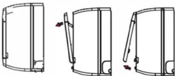
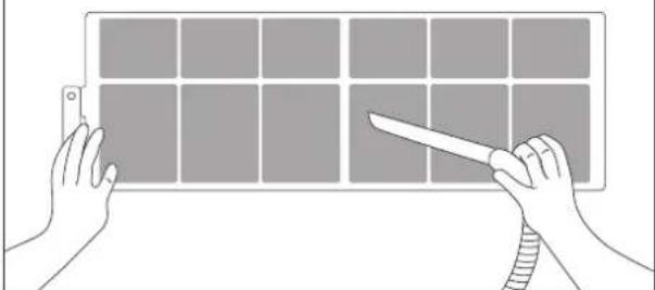
Fig.5.2.1 Fig.5.2.2 Fig.5.2.3
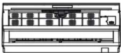
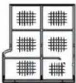
Fig.5.2
- Open the front panel.
- Lift the protruding part, then pull it down and remove the air filter.
- Clean it with a vacuum cleaner or water. If the air filter is very dirty, clean it with warm water and a mild soap or detergent. Then dry it in the shade.
- Insert the air filter in the previous position and close the front panel.

ATTENTION
- The air filter should be cleaned at least once every two weeks, otherwise the heating or cooling capacity will be reduced.
- Do not clean the air filter with a metal brush; could be damaged.
5.3 MAINTENANCE WHEN NOT IN USE FOR A LONG TIME
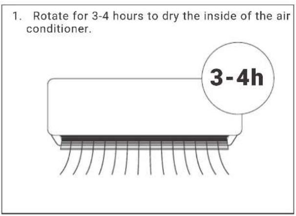
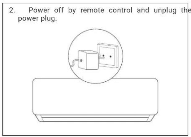
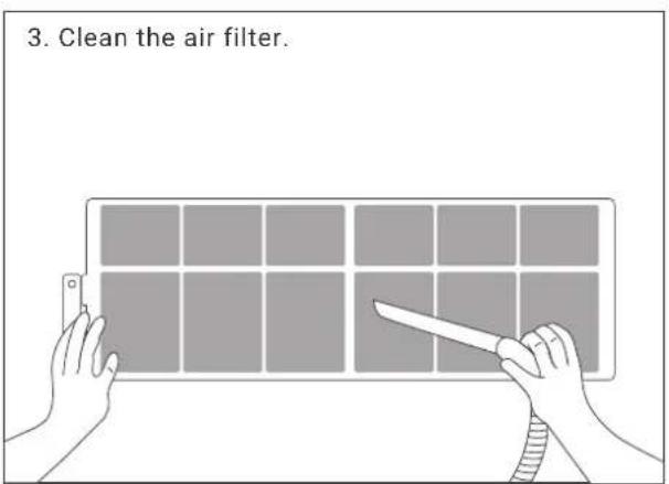
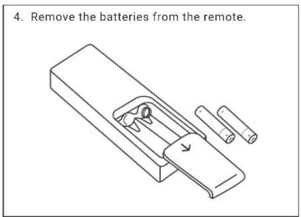
5. MAINTENANCE
5.4 ENERGY SAVING
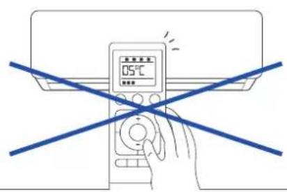
Enter the proper temperature.
Do not set the indoor temperature too low if the room is too cold. and harmful to health.
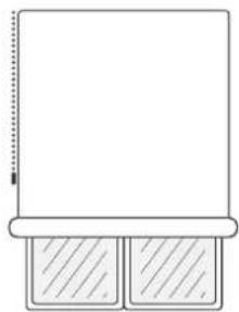
Avoid direct sunlight.
When cooling a room, use a curtain to block direct sunlight.
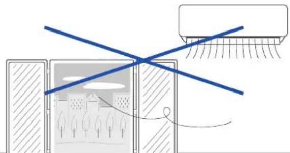
Avoid direct heat sources.
Close doors and windows tightly.
Incoming outside air will affect cooling or heating efficiency.
Air Filter Cleaning.
Keeping the air filter clean at all times ensures high efficiency of air conditioning operation.
Good ventilation.
Do not place any objects in front of the entrance and exit of the outdoor unit.
6.1 AIR CONDITIONING ERRORS
Check before repair:
| Type of fault Checks to be made | |
| The air conditioning does not work | 1. Check if the power is off. |
| 2. Check whether the switch is on or whether the fuse is blown. | |
| 3. Check the batteries in the remote. | |
| 4. Check whether the entered operating time has been reached. | |
| 5. Check if any working radio equipment works within 1 meter. | |
| Poor cooling or heating performance | 1. Check if the intake vents are blocked. |
| 2. Check whether the switch is on or whether the fuse is blown. | |
| 3. Check the batteries in the remote. | |
| 4. Check whether the entered operating time has been reached. | |
| 5. Check if any working radio equipment works within 1 meter. | |
6.2 REMOTE CONTROL ERRORS
Normal failure phenomena:
| Type of fault Failure Reason | |
| Unable to control stops or fan speed | 1. When the air conditioner is in DRY or SLEEP mode, the fan speed cannot be controlled. |
| 2. When the air conditioner is in COOL AIRFLOW TEST or DEFROST mode. | |
| 3. (In HEAT mode), the fan motor stops. | |
| 4. When the air conditioner is in COOL or DRY mode, if the air conditioner switches to antifreeze mode, the fan speed cannot be controlled. | |
| 5. When the air conditioner is in COOL or DRY mode, if the air conditioner enters freeze prevention mode, the speed cannot be controlled. | |
| 6. When the air conditioner is in HEAT mode, if the air conditioner enters heating overload prevention mode, the fan speed cannot be controlled. | |
6. TROUBLESHOOTING
6.3 ERROR CODES
| Códigos de error | Descripción |
| EE The EEPROM error on the indoor unit PCB | |
| PG FO motor failure | |
| F3 Indoor unit coil temperature sensor failure | |
| PG-E1 El Motor Zero Crossing Abnormality Detection | |
| E8 External system error | |
| EF EEPROM error on outdoor unit PC board | |
| F6 Internal communications are not accepted | |
| F8 Communication failure between outdoor unit and IPDU | |
| E4/E3 Compressor failure | |
| F9 IPM module malfunction | |
| F5 Discharge pipe temperature sensor fault | |
| ES Induction temperature sensor failure | |
| F4 Indoor unit coil temperature sensor failure | |
| F2 Outdoor temperature sensor failure | |
| E2 External DC motor failure | |
7.1 FOREWORD

WARNING
Some models are R32 or other flammable refrigerants, which need to be operated and used in accordance with the instructions for use.
- Air conditioners should be stored in areas with no persistent sources of ignition, such as open flames, lighted gas appliances, electric heaters that are turned on, etc.
- Do not puncture or ignite the air conditioner.
- Before servicing or repairing an air conditioner with R32 refrigerant, a safety inspection must be carried out to ensure that the risk of danger is minimized.
- If the air conditioner leaks refrigerant, please open all doors and windows immediately, keep the room ventilated, turn off the power, and leave the room and call for repair.
- When installing or recolocating the air conditioner, be sure to bleed the refrigerant circuit to ensure it is free of air, and use only the specified refrigerant (R32). The presence of air or other foreign matter in the refrigerant circuit causes abnormal pressure rise, which may result in equipment damage and even injury.
- The vacuum pump must be used for evacuation, and it is strictly prohibited to use the refrigerant in the fuselage to evacuate.
- After completing installation, check for refrigerant gas leakage.
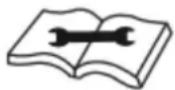
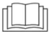
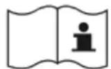
- Please check the following safety signs carefully before installing and using the air conditioner.
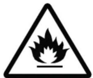
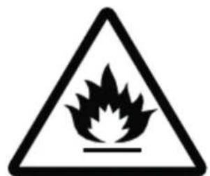
Caution, risk of fire

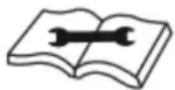
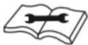
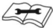
Please read the maintenance manual carefully!
Please read the instruction manual carefully!
Please read the installation instructions carefully!
7. INSTALLATION
7.2 INSTALLATION GUIDE
- This air conditioner meets the safety and operation standards promulgated by the Nation.
- You need to invite professional air conditioner service and maintenance personnel to install or remove the air conditioner. Problems may occur and you may suffer losses if non-professionals install the air conditioner.
- User shall provide the power that meets installation and operation requirements. please refer to nameplate for details about the voltage for this product. Voltage beyond this scope will affect the normal operation of the air conditioner.
- Separate power point with delay fuse protector or automatic breaker should be used for the airconditioner.
The air conditioner must be correctly and reliably grounded, or it may cause electric shock or fire. - Do not switch on the power of the air conditioner before well connecting and carefully checking the tubing and wires.
- The appliance shall not be installed in laundry or bathroom.
- In case necessary, please consult your supply authority for system information.
- The plug shall be accessible after installed the appliance.
- This instruction is subject to change without notice.
Installation of Accessories
- Examine carefully the attached packing list and check whether the accessories are complete.
- Users may need to buy at their own expenses the articles not included in the packing list and may be needed in installing.
7.3 POSITION FOR INDOOR UNIT
- Away from the place where there is heat source, steam source, leakage of flammable gas and smoke.
- No obstacles near the inlet and outlet, and keep good ventilation.
Good discharge for water. - At least 1m away from wireless equipment (such as TV, radio etc.).
- Mounted on the wall that can bear the weight of the air conditioner and won't produce noise while unit working.
- The distance between the indoor unit and the floor should be greater than 2.3m .
- The plug shall be accessible after installing the appliance.
- Ensure the distance as required in Fig.1.
- The back of the indoor unit should be close to the wall (Fig.1)
- The all figures are only schematic, and they may be slightly different from the actual appliances you selected.
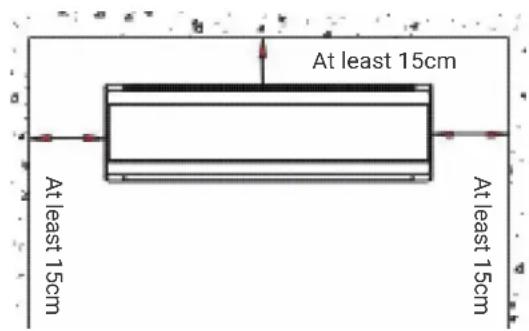
Fig.1
7.4 POSITION FOR OUTDOOR UNIT
- Avoid direct sunlight.
- Away from heat source, steam source, leakage of flammable gas, smoke and dust.
- Select a place that is away from rain (snow) and has good ventilation.
- Neighbors will not be affected by the blown wind and noise, or discharged water.
- The place that is easy to install and service.
- Mounted on the solid and reliable foundation will not increase noise or shock.
To get high cooling performance, make sure the unit's front, rear, left and right sides must be located in an open area. - The outlet is proposed to be in open air, any obstacle will affect the performances.
- The installing distance must be required as Fig. 2 shows.
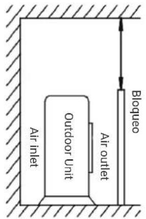
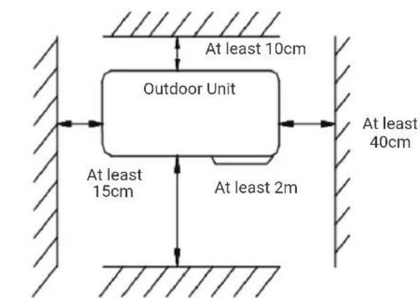
Fig.2
7.5 TUBING SELECTION
- Ensure that the level (height) difference of indoor and outdoor units and the length of tubing meet the requirement in the Table 1.
If the tubing is longer than 7m but shorter than 15m refrigerant should be supplemented according to Table 1. - If the installation position of the outdoor unit is higher than indoor unit and the tubing is longer than 10m , added a oil trap on the gas tubing for every 8m.(Fig 3)
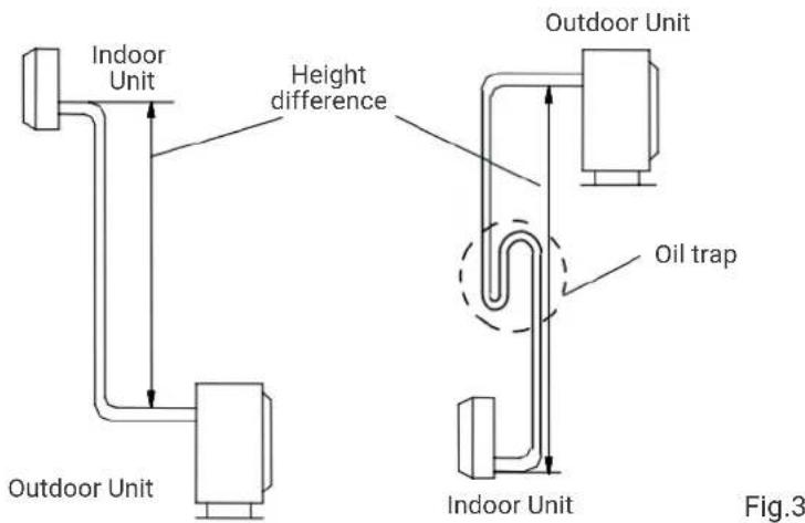
Table 1
| Model Supply hose Interconnecting hose | ||
| HTW-S026EON-R32 2*2,5+T 4*1,5+T | ||
| HTW-S035EON-R32 2*2,5+T 4*1,5+T | ||
| HTW-S052EON-R32 2*2,5+T 4*1,5+T | ||
The above dimensions are for reference only, actual product will prevail.
7.6 FIXING INSTALLATION PANEL
- Dismantle the metal installation board of the indoor unit. Adjust the installation board to horizontal position. The height difference between the left and right sides of the installation board should less than 5mm. (Fig 4)
- Drill holes and insert plastic expansion tubes at the appropriate locations on the wall and fix the installationboard on the wall with M5x30 screws. Ensure that there must be at least 4 fixed points in the wall. Ensure installation board to horizontal position.
- Drill holes as Fig. 5 shows. The hole, 80mm in diameter, should slightly slide down outwards.
- Cut PVC tubes at a slight angle in the length shorter than wall thickness and inset it into the hole. (Fig.5)
- Mount the wall cap.
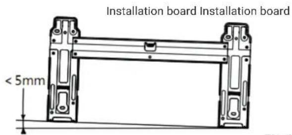
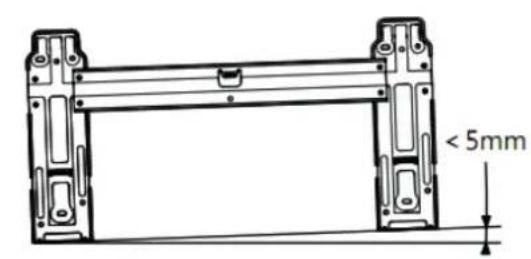
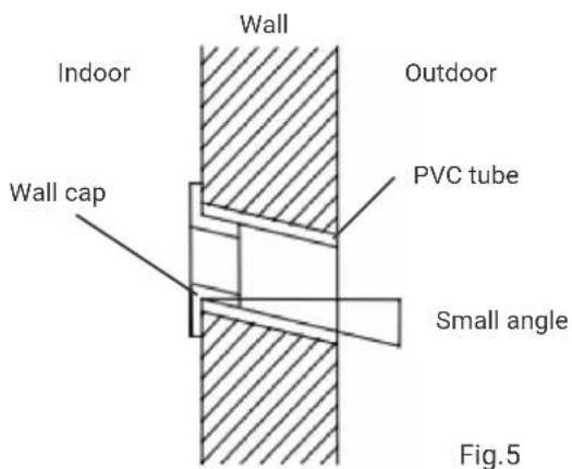
Fig.4
Attachment: Installation instructions for decorative cover plate
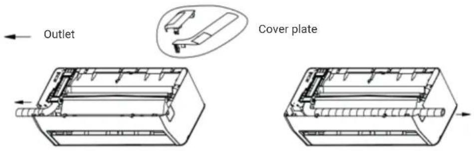
Step 1: Wrap PVC protective tape around drainage pipe, copper pipe and cable. Adjust the copper pipe tube to a suitable shape.

Step 2: Install the cover plate.

Step 3: Finish
Note: The above diagram may be difference from the actual product, please refer to the actual product.
7.7 INDOOR UNIT INSTALLATION
The tube may be connected in several directions as below shown Figures.
- Connecting right back tube (similar to right lower tube) (optional, Refer to Fig.6)
- Pull out the tubing from bottom of the chassis; and connect the drainpipe.
Strap the joint of tubing reliably. - Lead the connecting wire to the indoor unit (Do not connect to the power).
- Strap together the tubes, discharge pipe and connecting wire with adhesive tape. The discharge pipe is put at the below. Remove the board which is on the chassis.
- Check if the connections are reliable.
- Mount the indoor unit on the two hooks at the upper part of installation board. (Refer to Fig.8)
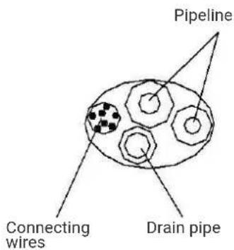
Fig.6
7. INSTALLATION
-
Connecting left back tube (similar to left lower tube). (optional, Refer to Fig. 9)
-
Move the discharge tube to the left side, and discharge cap to the right side.
Fix the tubes in the slot of the indoor unit with the fix clamp. - The following mounting steps are the same as those in "1. Connecting right back tube."
Notes: Left chart is available for the position of drain hose, refer to Fig 7. Right chart is available for the position of drain hose, refer to Fig 9.
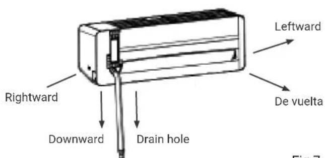
Fig.7
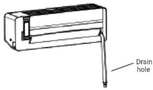
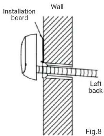
Fig.9
7.8 OUTDOOR UNIT INSTALLATION
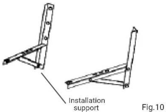
If installation brackets for installing outdoor unit are needed, user could buy the brackets from our company or agents (Fig.10)
- Assemble the mounting frame and supports with the attached 6 screws (M12x25), plain washers, spring washers, and nuts.
- Drill 4 or more holes on the wall according to the feet size of the air conditioner. Determine the locations for mounting left and right supports. Ensure that the left and right supports are on the same level.
Fix installation frame on the wall with expansive bolts.
Fix outdoor unit with 4 bolts (M10x25) on the installation brackets.
Fittings must be tightly screwed; Connection must be tight and reliable.
- In installing outdoor unit, the body should be hung with ropes to prevent from falling.
- In installing or repair, tools and components should be prevented from falling.
- Regularly check the reliability of the installation frame.
7.9 TUBING CONNECTION
- Detach the valve cover of outdoor unit.
- Align flaring nut to the thread center, and screw the nut tightly by hand.
- Screw tightly the flaring nut with torque spanner until the torque spanner produces "click" sound.
- It is recommended to use torque spanner to connect the tubing. If other flexible or fixed spanner is used, it may damage the horn mouth due to improper force.
- The bending angle of the tube should not be too small or the tube may break up, so the service personnel should use tube bender to bend the tube.
- Never let water, dust or sand gets into the pipe.
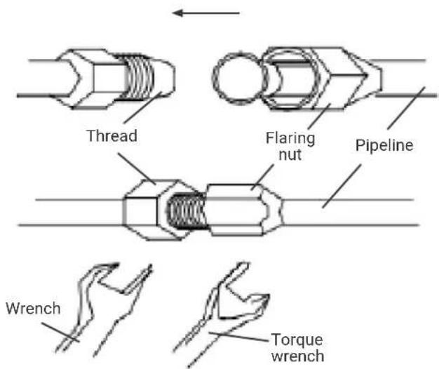
Fig.11
Table 2
| Tubing size (mm/inch.) | Torque (N.m) |
| Φ6 (1/4") 15~20 | |
| Φ9.52 (3/8") 35~40 | |
| Φ12(1/2") 50~55 | |
| Φ15.88 (5/8") 60~75 | |
| Φ19.05 (3/4") 80~95 |
7. INSTALLATION
7.10 WIRE CONNECTION
1. Indoor unit (fig.12)
- Open the panel upwards and open directly to the maximum.
- Open the electrical cover.
- Secure the connection wires to the terminal block according to the wiring diagram on the electrical cover.
- Press the connecting wire tightly with the pressure plate.
- Close the electrical cover, secure the electrical cover with screws, and close the panel.
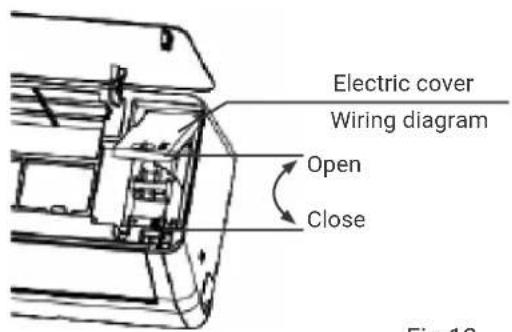
Fig.12
Note: Some models may not be able to directly pass through the cable hole into the electric control box, and the above steps need to be removed after removing the middle frame.
2. Outdoor unit (fig.13)
- Unscrew the handle cover fixing screw and open the handle cover.
- Secure the connection wires to the terminal block according to the wiring diagram on the handle cover.
- Press the connecting wire tightly with the pressure plate.
- Put the handle cover back and fasten with the screws.
- If customers need to extend or replace the power cord, please refer to Table 3 for specifications.
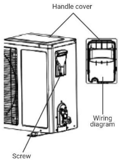
Fig.13
Table 3
| Model Maximum length (m) Maximum height (m) Additional load >5g/m | |||
| HTW-S026EON-R32 20 | 15 15 | ||
| HTW-S035EON-R32 20 | 15 15 | ||
| HTW-S052EON-R32 25 | 15 15 | ||
Notes:
- Earthing screw must use special screw (stainless machining screws or copper screws M4).
- Ensure that all wires are securely connected, will not loose or separate.
- Ensure that wire connections are carried out according to the wiring diagram of the air conditioner.
The above figures are only schematic, and they may be slightly different from the actual appliances you select.
7.11 TUBE STRAPPING
Strapping with PVC Protective tape must be careful, do not damage the pipeline and drain pipe.
- Strapping should start from the lower part of the outdoor unit to the indoor unit.
Fix the PVC tape with adhesive tape to prevent loosing.
- Drainpipe should slightly slide down outwards to ensure drainage well.
- When the indoor unit is lower than the outdoor unit, bend the tube to proper extent to prevent water draining into house.
Fix the tube bundle with tube clamps on the wall.
- Allow enough space between discharge pipe and the ground. Do not put the discharge pipe in water or ditch.
- Seal the external wall holes with sealing gum or putty.
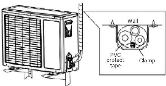
Fig.14
7. INSTALLATION
7.12 EXHAUST
- Make sure that all the tubes of indoor and outdoor unit are connecting well.
- Take off valve bonnet from two-way and three-way valves by spanner; connect vacuum pump and compound valve to the service valve bonnet.
- Open the low-pressure switch of compound valve, and run vacuum pump until units' internal pressure at 10mmHg .
After pump vacuum, close the low-pressure switch of compound valve, and then close vacuum pump. Turn anti-clockwise 90 Spool of narrow pipe service valve by hexagon spanner, tightly with clockwise turning after stopping for 10 seconds. - Check with soap water or leak detector whether there is leakage at all connections of indoor and outdoor unit. Open wide and narrow pipe service valves by hexagon spanner for running.
- Take off the connection pipeline of wide pipe service valve.
- Screw tightly the entire valve bonnet by torque spanner.
- Check with soap water or leak detector whether there are leakage at all indoor and outdoors' connections.
- Put the valve bonnet and lid back to position.
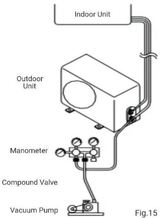
Fig.15
7.13 GAS LEAKAGE INSPECTION
After the pipeline connection is done, use a leakage inspection device or soap to carefully check if there is any leakage at the joints. This is an important step to ensure the quality of installation. If refrigerant leaks, ventilate the area immediately. Toxic gas may be produced if refrigerant gas comes into contact with fire. Never directly touch any accidentally leaking refrigerant. This could result in severe wounds caused by frostbite.
7.14 DRAINAGE
- No need drainage treatment
In regions where become cold in the winter, don't install the drain elbow joint to prevent drain water from freezing and causing the fan to be damaged. This drainage treatment is not necessary for cooling-only type air conditioner.
- When need drainage treatment
Please use drain elbow joint (in accessory bag). Outdoor unit should be placed on blocks.
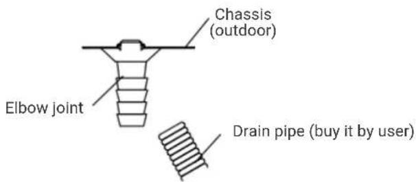
Fig.16
7.15 INSTALLATION FOR THE COVER OF VALVE
- For the whole unit that individual cover of valve is available (refer to packing list), the installing method is as follow:
- After connecting the connection pipes between indoor and outdoor units followed by the installing method mentioned above, take out the cover of valve from the accessory bag, and fix it on the side of outdoor unit with three corresponding screws (inside the accessory bag).
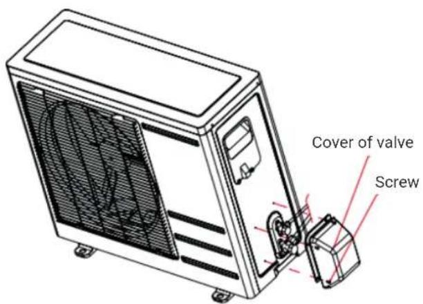
Fig.17
8.1 DOWNLOAD AND INSTALL THE APP


GIApp
FORAndroid
Method 1: Scan the QR code with the browser scanner, download and install the APP.
Method 2: Open Google "Play Store" of your smartphone, search "GIApp", download and install the APP.

FOR IOS
Method 1: Scan the QR code and follow the tips to enter "AppStore", download and install the APP.
Method 2: Open Apple "APP Store" of your smart phone and search "GIApp" download and install the APP.


Note
Please enable Storage/Location/Camera permissions for the App when you install it. Otherwise, some problems may appear when operating.
8.2 SIGN UP
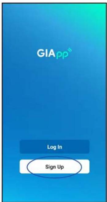
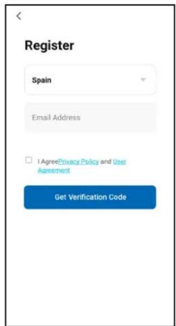
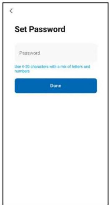
When you open the app for the first time, start your registration. Click on "Sign Up", enter your email address, check the box "I Agree with the Privacy Policy and User Agreement", click on "Get Verification Code" and receive a verification code.
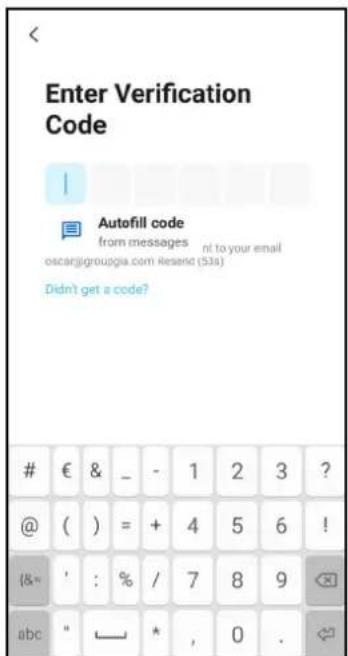
Enter the code, confirm your password, and then tap "Done". After successful verification, the registration process is over and the application goes to the home page.
8.3 LOG IN
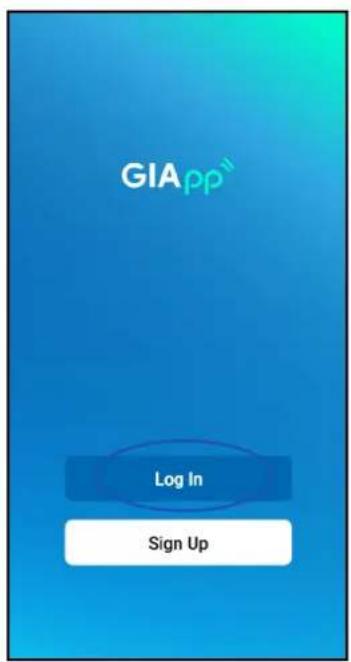
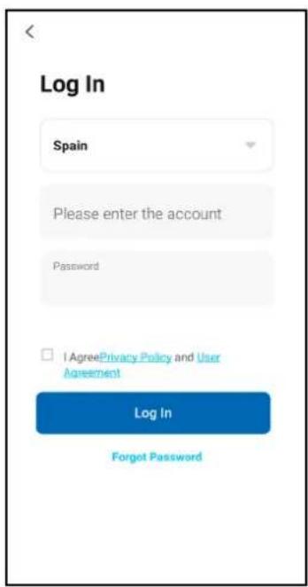
Click "Log In", choose your country, enter the registered account and password, and tap the "Log In" button.
8.4 ADD A DEVICE
- Connect. Make sure the device is waiting to be connected. If not, reboot the device via either of the following two methods:
Method 1: Holding the reset button for 5 seconds. A buzz will be emitted. The WiFi icon on the device will flash rapidly (approx. 3 times). Then it will indicate that the device has been reset successfully and enter Smart mode.
Method 2: Turning on the air conditioner and pressing "DISPLAY" button 6 times within 7 seconds, a buzzer will be emitted. The WiFi icon on the device will flash rapidly (approx. 3 times). Then it will mean that the device has been reset successfully and is online. -
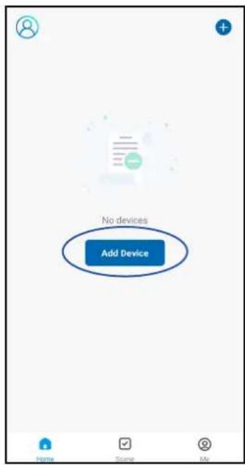
Pairing the device. Open the application, and activate the "Add device" option, select your Wi-Fi network, write the password of your Wi-Fi router and press "Next". Then the network setup will start.
-
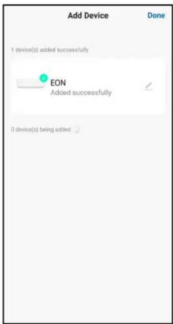
Setting. When the configuration is successful, a screen like the following will appear. Click "Done", and you can see the device interface ready as the following screenshot shown.
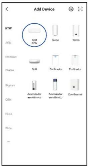
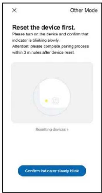
8.WIFI SETUP
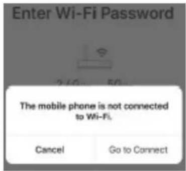
- If the mobile is not connected with Wi-Fi from the router, the interface will automatically jump to the following interface:
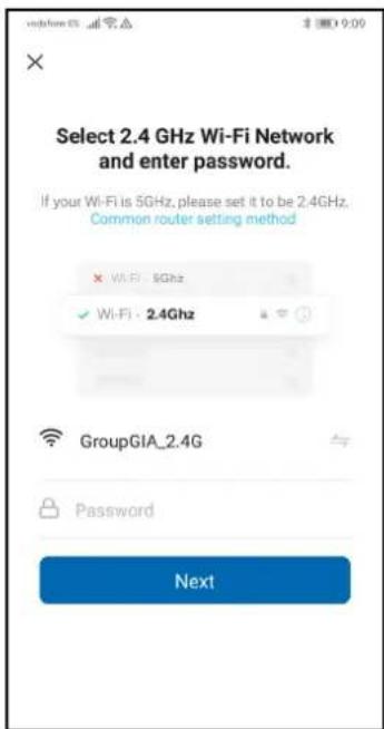
- Select your Wi-Fi network (2.4GHz), type your own Wi-Fi router password and tap "Next".
- Device control. When the device is successfully connected, the first capture screen will appear. If you press on it, it will take you to the screen of the second capture, from which you can control the device.
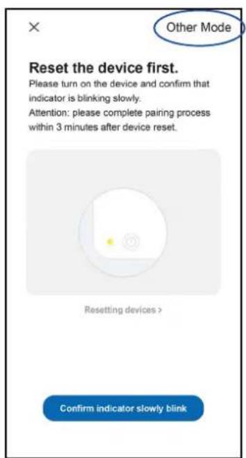
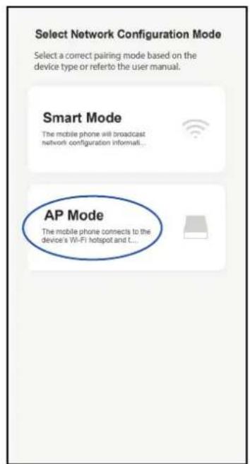
- And if the connection fails? When the connection fails, you can see the application interface as below screenshot shown. Please try to configure the network again or switch to AP mode.
8.WIFI SETUP
Continue connecting by switching to Other Mode. Tap AP Mode, set the network via AP mode by following steps:
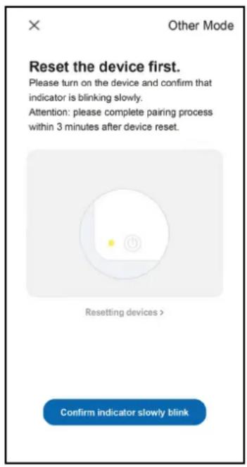
- Switch the air conditioner to AP mode when in Smart mode by long press the reset button for 5 seconds; then it will buzz, the heating icon on the device will flash slowly (approx. 1.5 times/s). This indicates that the device has entered AP mode.
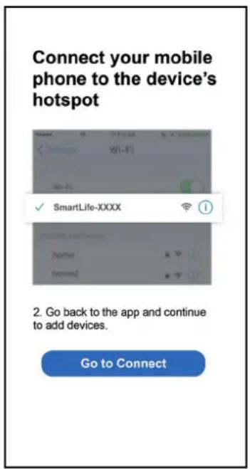
- Connect to Hotspot: Click on Connect (open phone settings: WLAN). Connect to the access point named "SmartLife-XXXX" (WIFI name may vary depending on the actual product), then the network setting will start as shown in the screenshot.
After successful network configuration, tap "Done", and the device list interface will pop up.
8.5NOTICES
- The control quality of the app is affected by your smartphone, Wi-Fi network, distance from the router, and Internet status. It has nothing to do with the unit itself.
- If you find that you couldn't control the device with your smartphone, please check your internet status at first, then check if you are successfully connected with the unit. If everything is ok, delete the device in your app and start the procedures again.
- If you still can't solve the problems with the above methods, please use the unit with normal control and then ask for after-sale service.
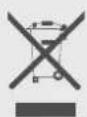
Air Conditioner Disposal
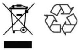
By ensuring this product is disposed of correctly, you will help avoid potential negative consequences for the environment and human health, which could otherwise be caused by inappropriate waste handing of this product.
The symbol on the product or onthe documents accompanying the product, indicates that this appliance may not be treated as household waste. Instead it shall be handed over to the authorized collection center for the recycling of electrical and electronic equipment waster generated at the end of life of the product. Disposal must be carried out in accordance with local environmental regulations for e-waste disposal, which mandate channelization of ewaste authoirzed collection center's) or registered dismantler (s) or recycler(s) or returned to the pick-up or take back services provided by the manufacturer.
EON
HTW-S026EON-R32 | HTW-S035EON-R32 | HTW-S052EON-R32
FRANÇAIS
Caution, risk of fire
Caution, risk of fire
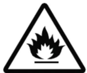
Caution, risk of fire
info@htwspain.com www.htwspain.com

Espana info@htwspain.com | France info@htwfrance.com
Portugal info@htw.pt | Italy info.it@htwspain.com

SAT
Espana sat@groupia.com
France sat.fr@groupgia.com
Portugal sat.pt@groupgia.com
Italy sat.it@groupgia.com
tel.+34933904220
tel. +33 465430168
tel. +39 05641715509

ADVERTENCIAS PARA LA ELIMINACION CORRECTA DEL PRODUCTO SEGUN ESTABLECE LA DIRECTIVA EUROPEA 2002/96/EC.
At the end of its working life, the product must not be disposed of as urban waste. It must be taken to a special local authority deifferentiated waste collection centre or to a dealer providing this service. Disposing of a household appliance separately avoids possible negative consequences for the environment and health deriving from inappropriate disposal and enables the constituent materials to be recovered to obtain significant savings in energy and resources. As a reminder of the need to dispose of household appliances separately, the product is marked with a crossed-outwheeled dustbin.
AVERTISSEMENTS POUR L'ELIMINATION CORRECTE DU PRODUIT AUX TERMES DE LA DIRECTIVE 2002/96 / CE.