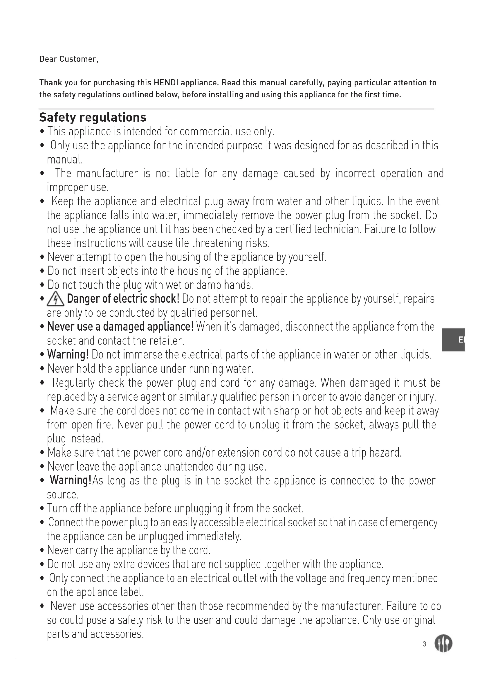
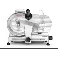
USER MANUAL 210048 Hendi
210000, 210017, 210031, 210048, 210086, 970294
natural_image
Exterior view of a HENDI commercial microwave oven (no signage or text visible on the device itself)
You should read this user manual carefully before using the appliance.
Keep these instructions with the appliance.
Diese Gebrauchsanweisung bitte beim Gerät aufbewahren.
Bewaar deze handleiding bij het apparaat.
Zachowaj instrukcję urządzenia
Gardez ces instructions avec cet appareil.
Conservate le istruzioni insieme all'apparecchio.
Păstrați maualul de utilizare alături de aparat.
Хранить руководство вместе с устройством.
Фулăște autės tics ođnyiες μαzi με τη συσκευή.
Čuvajte ove upute uz uredaj.
Tieto pokyny si odložte so spotrebičom.

natural_image
Simple house icon with left-pointing arrow, labeled 'INDOOR' below (no other text or symbols)
For indoor use only.
Nur zur Verwendung im Innenbereich.
Alleen voor gebruik binnenshuis.
Do użytku wewnątrz pomieszczeń.
Pour l'usage à l'intérieur seulement.
Destinato solo all'uso domestico.
Doar pentru uz la interior.
Использовать только в помещениях.
Гид хрňση μόνο σε εσωτερικό χώρο.
Samo za unutarnju uporabu.
Len na použitie v interiéri.

natural_image
Symbol of a trash bin crossed out by diagonal lines, no text or numbers present
CE

For item 210017 only.
Nur für Artikel 210017.
Alleen voor artikel 210017.
Dla pozycji numer 210017 tylko.
Pour l'article 210017 seulement.
Solo per articolo 210017.
Numai pentru articolul 210017.
Только для элемента 210017.
Гіа то отоихею 210017µovo.
Samo za stavku 210017.
Len pre položku 210017.
Thank you for purchasing this HENDI appliance. Read this manual carefully, paying particular attention to the safety regulations outlined below, before installing and using this appliance for the first time.
Safety regulations
- This appliance is intended for commercial use only.
- Only use the appliance for the intended purpose it was designed for as described in this manual.
- The manufacturer is not liable for any damage caused by incorrect operation and improper use.
- Keep the appliance and electrical plug away from water and other liquids. In the event the appliance falls into water, immediately remove the power plug from the socket. Do not use the appliance until it has been checked by a certified technician. Failure to follow these instructions will cause life threatening risks.
- Never attempt to open the housing of the appliance by yourself.
- Do not insert objects into the housing of the appliance.
- Do not touch the plug with wet or damp hands.
- Danger of electric shock! Do not attempt to repair the appliance by yourself, repairs are only to be conducted by qualified personnel.
- Never use a damaged appliance! When it's damaged, disconnect the appliance from the socket and contact the retailer.
- Warning! Do not immerse the electrical parts of the appliance in water or other liquids.
- Never hold the appliance under running water.
- Regularly check the power plug and cord for any damage. When damaged it must be replaced by a service agent or similarly qualified person in order to avoid danger or injury.
- Make sure the cord does not come in contact with sharp or hot objects and keep it away from open fire. Never pull the power cord to unplug it from the socket, always pull the plug instead.
- Make sure that the power cord and/or extension cord do not cause a trip hazard.
- Never leave the appliance unattended during use.
- Warning! As long as the plug is in the socket the appliance is connected to the power source.
- Turn off the appliance before unplugging it from the socket.
- Connect the power plug to an easily accessible electrical socket so that in case of emergency the appliance can be unplugged immediately.
- Never carry the appliance by the cord.
- Do not use any extra devices that are not supplied together with the appliance.
- Only connect the appliance to an electrical outlet with the voltage and frequency mentioned on the appliance label.
-
Never use accessories other than those recommended by the manufacturer. Failure to do so could pose a safety risk to the user and could damage the appliance. Only use original parts and accessories.
-
This appliance should not be operated by persons with reduced physical, sensory or mental capabilities, or persons that have a lack of experience and knowledge.
- This appliance should, under any circumstances, not be used by children.
- Keep the appliance and its power cord out of reach of children.
- WARNING: ALWAYS switch off the appliance and unplug from power socket before cleaning, maintenance or storage.
Special Safety Regulations
• CAUTION! Unplug before cleaning, maintenance or repair!
• O! ION! Two-person handling required!
• CAUTION! Read instruction manual before operation, cleaning or maintenance!
- The food to be sliced must be thawed, unpacked and free from bones before it can be sliced with the appliance. Do not use the appliance for slicing frozen food, vegetables or for any other purpose.
- Use the appliance only as described in the manual.
- Any other use might lead to damage to the appliance or personal injury.
- This appliance should be operated by trained personnel.
- Do not place the appliance on a heating object (gasoline, electric, charcoal cooker, etc.) Keep the appliance away from any hot surfaces and open flames. Always operate the appliance on a level, stable, clean, heat-resistant and dry surface.
- Danger of injury! Care is needed when handling the blade, especially when removing the blade for cleaning. Wear protective gloves (not supplied) if necessary.
- Caution! Securely route the power cord if necessary in order to prevent unintentional tripping over and falling.
- Do not use the appliance before it is properly assembled with the blade, blade guard and the food holder.
- Do not use the appliance near explosive or flammable materials, credit cards, magnetic discs or radios.
- Never bypass any safety interlocks on the appliance.
- WARNING: Keep all ventilation openings in the appliance clear of obstruction.
- WARNING: ALWAYS switch OFF the appliance and unplug from electrical power supply before cleaning, maintenance or storage.
- WARNING: ALWAYS keep hands, long hair and clothing away from the moving parts.
- Allow at least 20 cm spacing around the appliance for ventilation purpose during use.
- WARNING! Take great care when handling the cutting discs. Wear protective gloves (not supplied) if necessary.
Intended use
- This appliance is intended for professional use.
- The appliance is designed only for slicing foodstuff, e.g. meats, cheese, breads, etc. Any other use may lead to damage to the appliance or personal injury.
- Operating the appliance for any other purpose shall be deemed a misuse of the device. The user shall be solely liable for improper use of the device.
Grounding installation
This appliance is classified as protection class I and must be connected to a protective ground. Grounding reduces the risk of electric shock by providing an escape wire for the electric current.
This appliance is fitted with a power cord that has a grounding wire and grounded plug. The plug must be plugged into an outlet that is properly installed and grounded.
General precautions
- The slicer must be operated only by highly qualified people who are fully aware of the safety measures described in this manual.
- In case of personnel rotation, training is to be provided in advance.
- Although the slicer is equipped with safety devices in the dangerous points, it is recommended not to touch the blade and the moving components.
- Before starting cleaning and maintenance operations, disconnect the slicer plug from the supply.
- Assess the residual risks carefully when protection devices are removed to carry out cleaning and maintenance.
- Cleaning and maintenance require great concentration.
- A regular control of the electric supply cord is absolutely necessary; a worn-out or damaged cord can expose users to great electric shock hazard.
-
If the slicer shows malfunctions, it is recommended not to use or attempt to repair the device; please call the "SERVICE CENTRE".
-
Do not use the slicer for frozen products, meat and fish with bones and any products other than foodstuffs.
- Do not use the slicer without the meat pusher when the meat is nearly finished.
- Do not place yourself in a dangerous position, the blade may cause injuries.
The manufacturer and/or the seller is not liable in the following cases:
- if the slicer has been tampered by non-authorized personnel;
- if some parts have been substituted by non-original spare parts;
- if the instructions included in this manual are not followed accurately;
- if the slicer is not cleaned and oiled with the right products.
Safety systems installed in the slicer
The slicer is equipped with:
- a micro-switch which stops the slicer in case the tie rod for blade guard is removed; the micro-switch prevents from restarting the slicer if the guard has not been set in the switch-off position.
- a relay in the control box which requires the restart of the slicer when a power cut occurs.
Even though slicers are provided with electrical and mechanical protections (when the slicer is operating and for maintenance and cleaning operations), there are still RESIDUAL RISKS that cannot be eliminated completely; these risks are specified in this manual under WARNING. The blade and other parts of the machine can cause cuts and injuries.
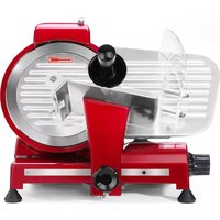
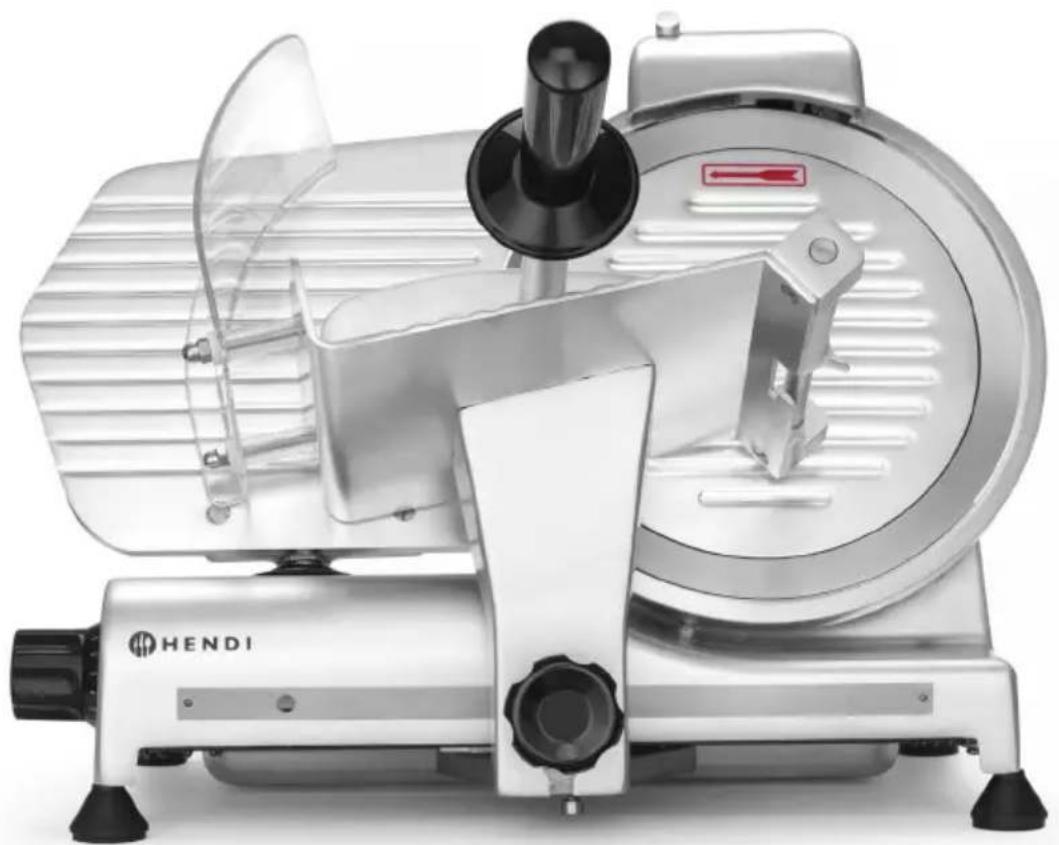
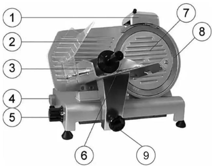
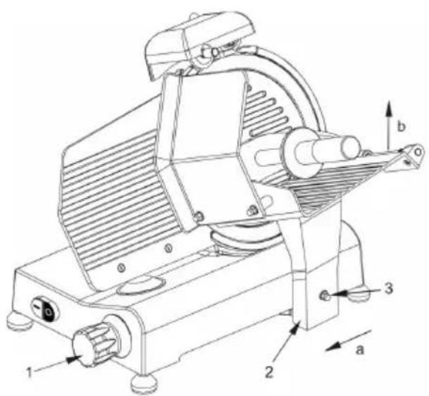
Main parts of the appliance
1 Blade sharpener
2 Stop plate
3 Carriage
4 On/off switch
[White (I): ON; Black (O): OFF]
5 Slice thickness dial
6 Product clamp
7 Blade guard
8 Blade
9 Carriage lock
10 Blade guard bolt (not displayed)
Preparations before using for the first time
- Check to make sure no parts are missing. If any parts are missing, contact your supplier.
- Remove all the packing material.
- Keep the packaging if you intend to store your appliance in the future.
-
Check the appliance for completeness and transport damages. In case of incomplete delivery or damage, contact supplier immediately. DO NOT use the appliance. (See ==> Warranty).
-
Clean the blade. Be careful: the blade is very sharp. (Use gloves if necessary, not included)
- Keep open a space of at least 10 cm around the appliance to allow for adequate ventilation.
- Position the appliance in such a way that the plug is always accessible.
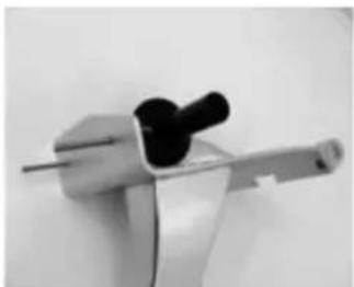
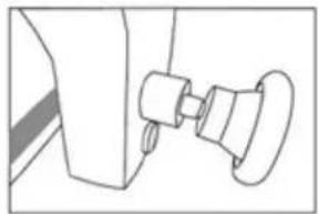
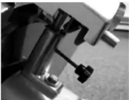
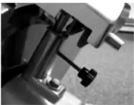
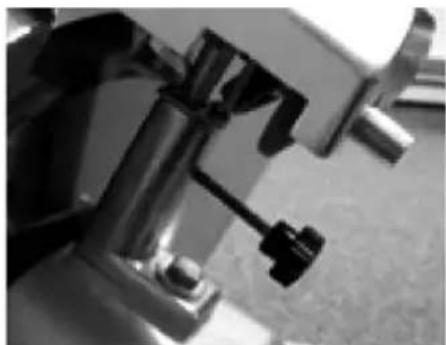
- If the sharpening device is not attached, proceed as follows:
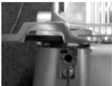
natural_image
Close-up of a metallic mechanical component with a cylindrical base and mounting bracket (no visible text or symbols)

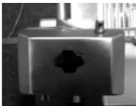
natural_image
Close-up of a metallic mechanical component with a central hole, possibly a valve or vent (no visible text or symbols)
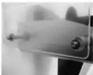
natural_image
Close-up of mechanical components with no visible text or symbols
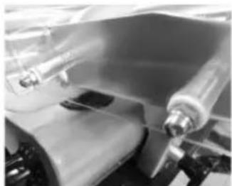
- Top view of the appliance 2. Attach the sharpening module
in such a way that the blade does not move between the wheels.
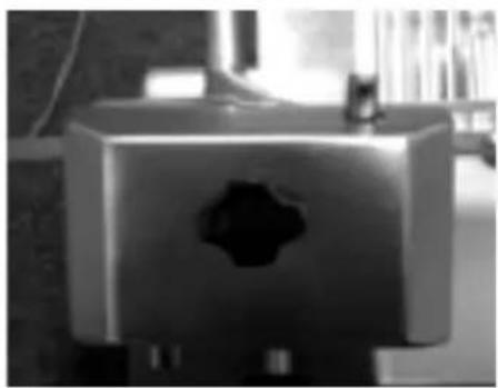
- Secure the sharpening device to the machine by tightening the holder. Check to make sure that the sharpening device is well secured before using the machine.
NOTE! The sharpening device is equipped with a safety switch. If the sharpening device is not properly attached, you will not be able to use the appliance.
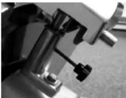
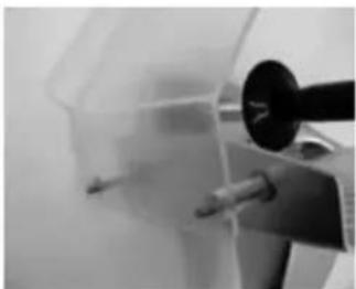
- Attach the hand guard.
natural_image
Close-up of a metallic mechanical clamp or bracket with a black handle (no visible text or symbols)
- Place both screws in the carriage.
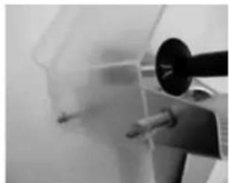
natural_image
Close-up of a mechanical device with a transparent container and a black dial (no visible text or symbols)
- Attach the hand guard.
natural_image
Close-up of a hand holding a small mechanical component (no visible text or symbols)
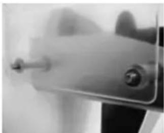
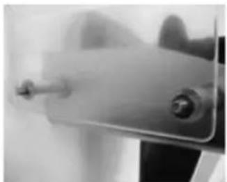
- Place the two washers over the white bolts.

natural_image
Close-up of mechanical components with no visible text or symbols
- Screw on the two dome nuts.
NOTE! You are advised not to use the appliance if the hand guard is not attached as instructed! These are safety features that will prevent possible injury. If you do not attach these features, there will be a risk of injury.
Instructions for use
- Position the appliance so that the on/off switch is facing the user.
- If the blade sharpener has not been installed, proceed as follows:
- Position the blade sharpener in its support so that the blade does not extend between the gears.
- Tighten the safety screw on the blade sharpener.
- Note! The appliance is equipped with a safety switch and will turn off automatically if the sharpening device is removed)
- Push the plug in the wall socket.
- Turn the dial with the graduated scale to the desired slice thickness.
- Switch ON the appliance by pressing the "WHITE (I)" button of the ON/OFF switch.
- Put the food product on the carriage and adjust the clamp to hold the product firmly in place. Make sure the product is positioned against the stop plate.
- Once the product has been sliced, switch OFF the appliance by pressing the "BLACK (O)" button of the ON/OFF switch.
- Turn the thickness dial back to "0".
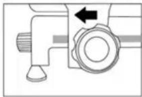
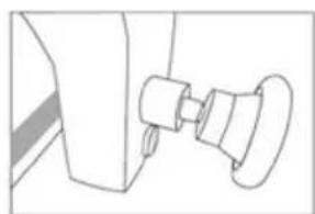
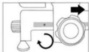
How to Lock the slicer
① To turn the knob in anti-clockwise direction
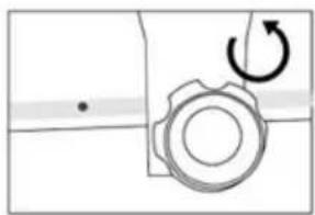
natural_image
Pure mechanical diagram showing a gear and rotational arrow without any text or symbols
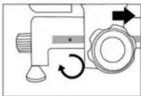
② Continue to turn the knob until it is loosen COMPLETELY
natural_image
Simple line drawing of a mechanical component with no text or symbols
③ Move the carriage to the proper position, the slicer will be locked automatically
natural_image
Mechanical component diagram showing a valve and pump assembly with an arrow indicating direction (no text or symbols)
How to Unlock the slicer
① To turn the knob in clockwise direction to unlock the slicer. The knob should be turned COMPLETELY to tighten the carriage
natural_image
Mechanical component diagram showing a valve and gear mechanism with rotational arrows (no text or symbols)
Loading and slicing of foodstuffs
WARNING: Products to be cut must be loaded on the food tray only when the dial knob is set to the "0" position. Pay attention to the blade and the sharp edges.
The procedure is as follows:
- once the product has been loaded onto the food tray and placed against the plate, stop it with the arm provided with gripping points;
- adjust the dial knob so as to obtain the desired cutting thickness;
-
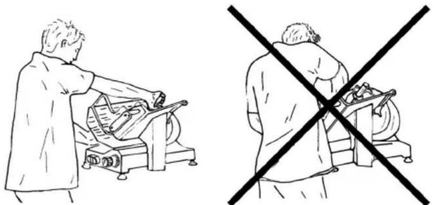
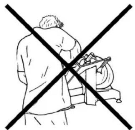
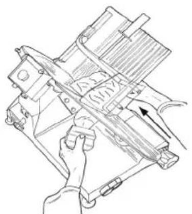
to avoid accidents, the operator has to face the machine and adopt a correct position: put the ring hand on the meat pusher, and then the left one beside the deflector (do not touch the blade); the body must be perpendicular to the working surface (see FIG. 1a). WARNING: Pay maximum attention: no part of your body should contact the blade (see FIG. 1b);
-
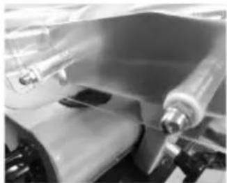
push the switch-on button "1";
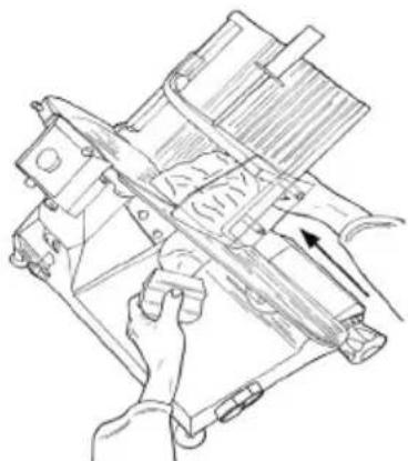
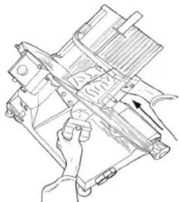
- smoothly push the carriage (food tray + meat pusher + stem) towards the blade without exerting pressure on foodstuffs with the meat pusher since they have their own force of gravity which exerts pressure on the thickness gauge. The blade will easily cut foodstuffs and slicers will be guided by the deflector onto the collecting plate (see FIG. 2);
- do not operate the slicer without foodstuffs;
- once foodstuffs have been cut, set the dial knob in the "0" position and switch off the machine by setting the switch to the "0" position;
- resharpen the blade as soon as slices show a rough or frayed surface and the cutting becomes difficult (see Sharpening the blade).

natural_image
Two line drawings showing a person operating machinery and another holding a device, both crossed by a diagonal line (no text or symbols)
Fig. 1a. Right position Fig. 1b. Bad position
natural_image
Technical line drawing of a mechanical device with hands operating it (no text or symbols present)
Fig. 2. Cutting meat
Sharpening the blade
WARNING: Before proceeding with blade sharpening, remain alert to the RESIDUAL RISKS (see Electrical safety system) that refer to the hazard of injury if the instructions below are not followed.
The blade must be sharpened periodically and as soon as it becomes blunt; the detailed instructions below are to be followed:
- clean the blade accurately with alcohol to remove grease after the plug has been disconnected from the socket;
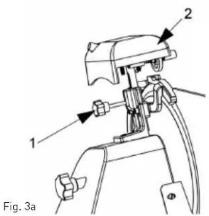
- unscrew the knob (1, Fig.3a), lift (a) the sharpener (2, Fig.3a) up to the locking position and rotate it 180^ .
Then let it move to the end so that the blade is positioned between the two sharpeners. Lock the knob;
- switch-on the slicer by pushing the button "I" (ON);
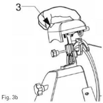
- push the small button (3, Fig. 3b), let the blade rotate against the sharpener for 30/40 sec. to produce a sharp burr on the blade edge;
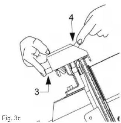
- push buttons simultaneously for 3/4 seconds (1 and 2, Fig 3c) and then leave them simultaneously;
- it is recommended to clean the sharpeners upon the end of sharpening (see Cleaning of the sharpener);
- once sharpening has been completed, return the slice to its original setting with the reverse procedure.
• after sharpening, the blade should be cleaned (See Cleaning of the blade guard and blade)
NOTE: Do not prolong the burring operation beyond 3/4 sec. in order to prevent the dangerous twisting of the blade cutting edge.
The blade should be replaced when it cannot be sharpened any further or when the gap between edge of the blade and the blade guard exceeds 6 mm.
Ordinary cleaning
General features
- The slicer cleaning must be carried out at least once a day or more frequently, if necessary.
- Cleaning must be extremely accurate for those parts of the slicer which are directly or indirectly in contact with foodstuffs.
- The slicer must not be cleaned with water-cleaner and high pressure water jets; use water and neutral detergent instead. Do not use other detergents. Tools, brushes and other devices likely to damage the slicer's surface must not be used.
Before carrying our any cleaning operation it is necessary to:
- disconnect the power supply plug from the socket to isolate the slicer from the rest of the electric circuit completely;
- set the dial knob adjusting the plate to the "0" position.
WARNING: Pay attention to residual risks due to cutting and/or sharp edges. Wear protective gloves (not supplied) if necessary.
Slicer cleaning procedure
Cleaning of the food tray
The carriage (food tray + arm + stem) is easily removable:
- set the dial knob in the "0" position (1)
- set the carriage (2) at the end of its run (a) near the controls;
- unscrew the screw(3), slide the carriage upwards (b);
- after having removed the carriage, it is possible to clean accurately the food tray with hot water and neutral detergent (pH 7).
Carriage removal
Cleaning of the blade guard and blade
- Remove the blade guard cover by unscrewing the pin at the back of the appliance (see Fig. 4).
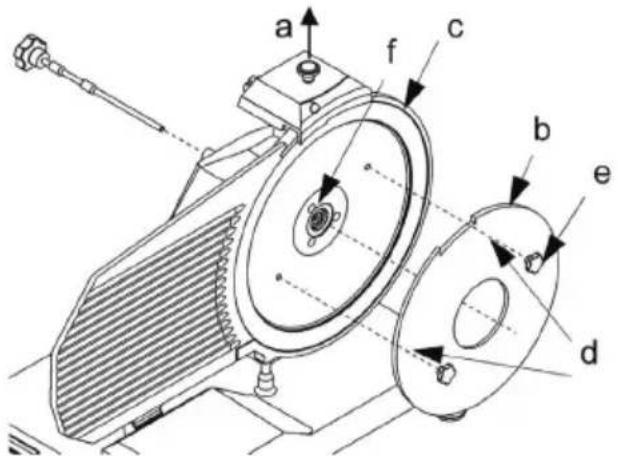
To clean the opposite surface of the blade it is necessary to remove the blade (see Fig. 5).
The blade is to be removed as follows:
• disassemble the blade guard(see Fig. 5);
- remove the sharpener (a) and turn the thickness blade with the dial knob to make the Plexiglas blade removal tool (b) (not supplied) adhere to the blade;
- loosen the 3 or 4 screws (f) (according to the model) that fix the blade;

natural_image
Line drawing of a machine with a circular component and hands holding a circular disc (no text or symbols)
Fig. 4 - Blade guard removal

- lean the Plexiglas blade removal tool on the blade to obtain the coupling of the blade holes with the two screws (e), turn the blade until it reaches the correct position;
- slightly tighten the screw (e).
WARNING: The blade guard must be cleaned with hot water and neutral detergent.

Fig. 5 - Assembling the Plexiglas blade removal tool (b)
Cleaning of the sharpener
The sharpener cleaning operation is carried out by rubbing the grinding moles with a brush. The moles must be placed in the safety position which
Cleaning of the deflector
To remove the deflector unscrew the two screws (a) locking the deflector (see Fig. 6).
Clean the deflector with hot water and neutral detergent.
means that they must be turned towards the side opposite to the blade.
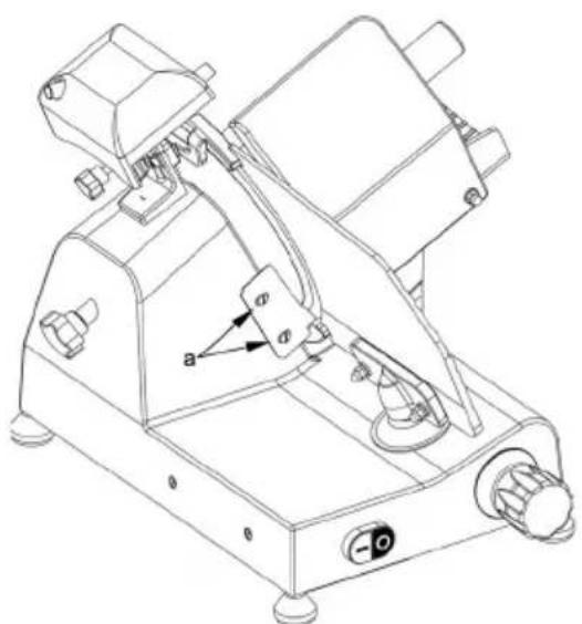
Fig. 6 - View of the deflector
Maintenance
General features
Before starting maintenance it is necessary to:
- Disconnect the power supply cord plug from the socket to isolate the slicer from the electric circuit completely.
- Place the dial knob adjusting the thickness plate in the "0" position.
Belt
The bell is not to be adjusted. Generally, it must be replaced after 3 or 4 years; in this case please call your authorized "SERVICE CENTER".
Feet
Feet may deteriorate and lose elasticity, thus reducing the stability of the slicer. In this case they must be replaced. Call your authorized "SERVICE CENTER" to replace the feet.
Power supply cord
Periodically check the power supply cord for any symptoms of worn-out and, if this is the case, please call the "SERVICE CENTER" to have it replaced.
Blade
Check that the blade does not lose more than 10mm of its original diameter. To have it replaced call the "SERVICE CENTER".
Sharpener - grinding moles
Check that the grinding moles retain their abrasive property during sharpening operations. Call the “SERVICE CENTRE” if it is necessary to replace the grinding moles to prevent the blade damage.
Lubrication of sliding guides
From time to time pou some oil drops onto the round sliding guide along which the carriage moves back and forth. This operation can be performed through the opening (OIL) next to the dial knob.
If the labels of the push-button panel have been damaged, call the "SERVICE CENTER" for replacement.
Machine disposal
Putting the machine out of service
If for some reason there is a necessity to put the machine out of service, make sure nobody can use
it: disconnect it from the mains and eliminate any the electrical connections.
Storage
- Before storage, always make sure the appliance has already been disconnected from the electrical outlet and cooled down completely.
- Store the appliance in a cool, clean and dry place.
Troubleshooting
If the appliance does not function properly, please check the below table for the solution. If you are still unable to solve the problem, please contact the supplier/service provider.
| Problem Possible cause | Use Solution | |
| Appliance does not slice evenly | Blunt blade Sharpen blade | ade |
| Dirty appliance Clean the appliance | e appliance |
| Appliance stops slicing | Overheated motor Let the machine cool off for an extended period. The motor's safety thermostat will reset itself automatically. |
| Carriage does not slide | Dirty slide bar Clean the slide bar and lubricate with Vaseline |
| Some food stick to the blade. | Switch off the appliance & unplug it. Let it come to a complete stop. Remove any blockage. Wipe the blade with a damp cloth. |
| Blade stops when product is being cut | v-belt worn out or dirty Contact the supplier. |
When in doubt, always contact your supplier!
Circuit diagram for 210000, 210017, 210031, 210048, 210086, 970294
AC voltage input: AC220-240V 50Hz
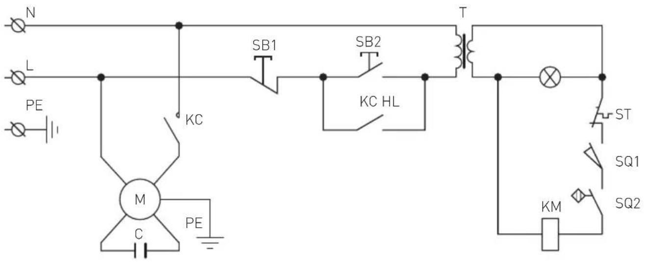
M : Motor
T : Transformer
C : Capacitor
PE : Protective earthing (Grounding)
L : Live
N : Neutral
SB1, SB2 : Switch
KC : Relay
HL : Indicator lamp
ST : Thermal cut-out
SQ1, SQ2 : Micro switch
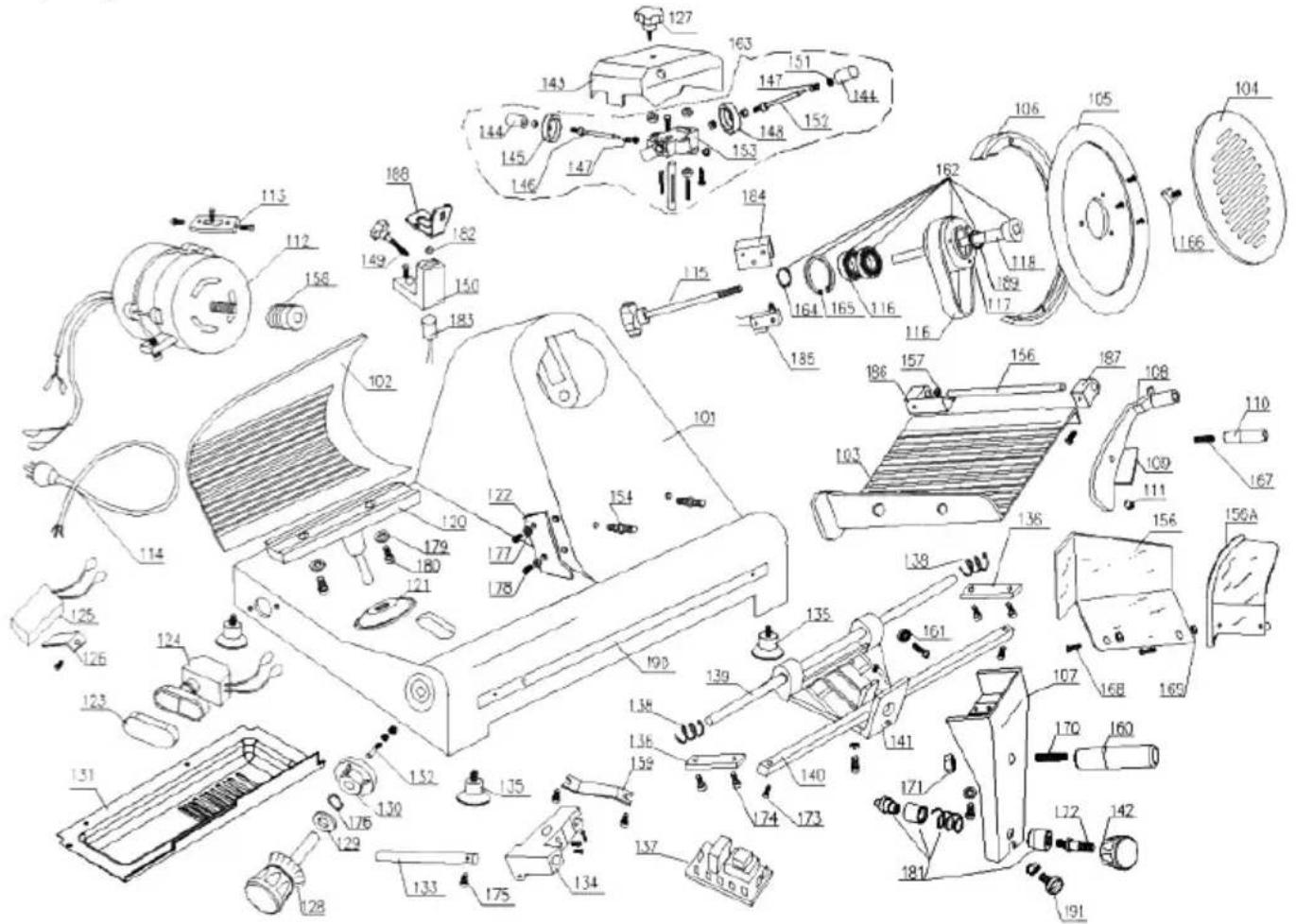
Part list (Item no: 210000, 210031, 210048, 210086, 970294)
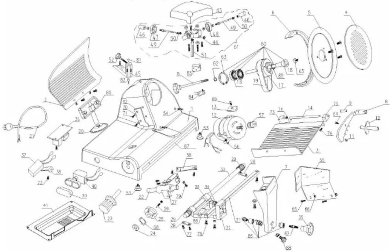
EN
| Part no. | Part name | Quantity Part no. | Part name | Quantity | | | |
| 1 | Encloser 1 | 20 Slide mulch 1 | | | | | |
| 2 | Active | lapboard 1 | 21 Power line 1 | | | | |
| 3 | Food salver | 1 | 22 Slide axle 1 | | | | |
| 4 | Blade guard disc | 1 | 23 Knob with scale 1 | | | | |
| 5 | Blade | 1 | 24 Spring gasket | | | 1 | |
| 6 | Blade guarding ring | 1 | 25 Cam | | | 1 | |
| 7 | Tray bracket | 1 | 26 Cam | osculant | staff | 1 | |
| 8 | Food and fixed-arm | 1 | 27 Slider | | | 1 | |
| 9 | Fixed-arm bushing | 1 | 28 Slide axle briquetting | | | 2 | |
| 10 | | Fixed-arm handle | | 1 | 29 | Spring of towing bracket axle | 2 |
| 11 | | Plastic granule | | 1 | 30 | Towing bracket axle | 1 |
| 12 | | Motor | | 1 | 31 Quad rate axis | 1 | |
| 13 | | Motor briquetting | | 1 | 32 | Towing bracket | 1 |
| 14 | | Fixed-arm pin ∅12×185 | | 1 | 33 | M8×35Hexagonal screw | 1 |
| 15 | | Blade guard bolts | | 1 | 34 | Ball bearing 607 | 1 |
| 16 | | Ball bearing 6202 | | 2 | 35 | Towing bracket cover knob | 1 |
| 17 | | Blade belt wheel ∅66 | | 1 | 36 Relay | 1 | |
| 18 | | Pin of belt wheel | | 1 | 37 Capacitor 1 | | |
| 19 | | BeltSV.330 | | 2 | 38 | Capacitor retainer | 1 |
| 39 Button | mulch 1 | 65 Fixed-arm handle bolt 1 | | | | | |
| 40 Button | switch 1 | 66 Finger baffle bolt 2 | | | | | |
| 41 Mother | board 1 | 67 Finger baffle nut 2 | | | | | |
| 42 Meats | scraper 1 | 68 Bracket knob bolt | | 1 | | | |
| 43 Sharpener mulch | 1 69 Undee spring gascket | 1 | |
| 44 Sharpener base of subassembly | 1 70 Motor impacted bolt | 1 | |
| 45 Sharpener base of assembled | 1 71 Meat scraping shim | 2 | |
| 46 Button of sharpener | 2 72 Meat scraper bolt | 2 | |
| 47 Fine grinding wheel ∅45 | 1 73 Capacitor fixation clamp | bolt 1 | |
| 48 Crude grinding wheel ∅45 | 1 74 Tray bearing cover A | 1 | |
| 49 Pin of rubbing stone | 2 75 Meat board bracket | 1 | |
| 50 Spring | 2 76 Tray bearing cover B | 1 | |
| 51 Pin of sharpener bracket | 1 77 Cross recessed countersunk head M6×12 | 2 |
| 52 Sharpener tighten knob 1 78 Slide axle briquetting bolt | 4 | | |
| 53 Active clapboard mandril | 1 79 Quadrate axis locking screw | 2 | |
| 54 Rubber foot | 4 80 Slider adjust bolt | 1 | |
| 55 Pin of blade guarding ring | 2 81 Magnet | 1 | |
| 56 Meat blocking board | 1 82 Magnet switch | 1 | |
| 57 Slide axle bracket | 2 83 Aluminium block | 1 | |
| 58 Small belt wheel of motor | 1 84 Microswitch 1 | | |
| 59 Slide driver | 1 85 Stainless steel lock | 1 | |
| 60 Belt wheel setting 1 86 Limited block | | 1 | | |
| 61 Sharpener setting | 1 87 Stainless steel bar | 1 | |
| 62 ∅15 Spring gasket for bearing | 1 88 Set screw for tray bracket | 1 | |
| 63 ∅15 Spring gasket for bearing | 1 89 Oil seal | 1 | |
| 64 Blade guard disc square-head nut | 1 | | | | |
Part list (Item no: 210017)

| Part no. | Part name | Quantity Part no. | Part name | Quantity | | | |
| 101 | Encloser | 1 119 Belt SV.400 2 | | | | | |
| 102 | Active | clapboard | 1 120 Supporting base 1 | | | | |
| 103 | Food salver | 1 121 Cable jacket 1 | | | | | |
| 104 | Guarding | blade disc | 1 122 | Mearscraper | | 1 | |
| 105 | blade | | 1 123 | Button mulch | | 1 | |
| 106 | Blade | guarding ring | 1 124 | Button switch | | 1 | |
| 107 | Tray bracket | | 1 125 | Capacitor | | 1 | |
| 108 | Food fixed-arm | | 1 126 | Capacitor retainer | | 1 | |
| 109 | Fixed-arm bushing | | 1 127 | Screw of oriented staff | | 1 | |
| 110 | Handle | | 1 128 | Knob with scale 1 | | | |
| 111 | Plastic | granule | 1 129 | Spring gasket | | 1 | |
| 112 | Motor | | 1 130 | Cam 300 | | 1 | |
| 113 | Motor | briquetting | 1 131 | Motherboard | | 1 | |
| 114 | Power line | 1 132 Cam osculant pin | | | 1 | | |
| 115 | Blade guard bolts | | 1 133 | Sliding axle | | 1 | |
| 116 | Ball bearing | 6204 | 2 134 | Slider | | 1 | |
| 117 | Belt wheel | 1 135 Rubber foot | | | 4 | | |
| 118 | Pin of belt wheel | | 1 136 | Sliding axle | briquetting | 2 | |
| 137 | Relay 1 | 165 ∅ 47 | Spring gasket for hole 1 | | | | |
| 138 | Spring | of sliding axle 2 | 166 Blade guard disc | square-head nut 1 | | | |
| 139 | Towing | bracket sliding axle 1 | 167 Fixed-arm | handle bolt 1 | | | |
| 140 | Quadrate axis 1 | 168 Finger baffle bolt 2 | | | | | |
| 141 | Towing | bracket | 1 169 | Finger baffle nut | 2 | | |
| 142 | Button | of towing bracket 1 | 170 Bracket knob bolt | | 1 | | |
| 143 | Sharpener mulch | 1 | 171 | Bracket knob nut | 1 | | |
| 144 | Button | 2 | 172 | Bracket bottom bolt | 1 | | |
| 145 | Fine grinding wheel ∅ 45 | 1 | 173 | Quadrate axis locking screw | 2 | | |
| 146 | Pin of burr cleaning wheel 2 | 174 | Slide axle briquetting | bolt | 4 | | |
| 147 | Spring | of burr cleaning wheel | 2 | Slide axle bolt | 1 | | |
| 148 | Crude grinding wheel ∅ 45 | 2 | 176 ∅ 12 | Under spring gasket | 1 | | |
| 149 | Sharpener tighten knob | 1 | 177 | Meat scraping shim | 2 | | |
| 150 | Supporting base of outer ring | 1 | 178 | Meat scraper bolt | 1 | | |
| 151 | ∅ 4.751 | Wheel | 1 | Fulcrum bearing shim 2 | | | |
| 152 | Pin of rubbing stone 1 | 180 | Fulcrum bearing bolt | 2 | | | |
| 153 | Sharpener base of subassembly 1 | | | 181 Stainless steel lock | 1 | | |
| 154 | pin of blade guading ring | 2 | | 182 Magnet 1 | | | |
| 155 | Pin of food tray | 1 | 183 | Magnet switch | 1 | | |
| 156/156A | Meat blocking board | 1 | | 184 Limited block | 1 | | |
| 157 | Bracket of sliding axle | 1 | 185 | Microswitch | 1 | | |
| 158 | Small belt wheel of motor | 1 | 186 | Tray bearing cover A | 1 | | |
| 159 | Slide transmitting wheel | 1 | 187 | Tray bearing cover B | 1 | | |
| 160 | Towing | bracket handle | 1 | Fulcrum bearing shim | 1 | | |
| 161 | Sliding axle608 | 1 | 189 | Oil seal | 1 | | |
| 162 | Belt wheel setting | 1 | 190 | Stainless steel bar | 1 | | |
| 163 | Sharpener setting | 1 | 191 | Set screw for tray bracket | 1 | | |
| 164 ∅ 20 | Spring gasket for bearing | 1 | | | | | |
Technical specifications
| Item no. 210031 210048 2100 | 00 210017 2100 | 86 970294 | | | | |
| Operating voltage and frequency | 220-240V~ / 50 Hz |
| Rated input power 200W 280 | W 320W 420W | 320W 280W | | | | |
| Blade diameter 195 mm 220 | mm 250 mm 3 | 00 mm 250 mm | 220 mm | | | |
| Waterproof protection class | P33 |
| Protection class Class I | |
| Noise level < 70 dB (A) | |
| Dimension 400x400x | (H)330 mm | 440x420x (H)350 mm | 485x420x (H)395 mm | 600x480x (H)450 mm | 485x420x (H)395 mm | 440x420x (H)350 mm |
| Net weight [approx] 13.5 kg | 14 kg 16 kg 26 kg | 16 kg 14 kg | | | | |
Remark: Technical specification is subjected to change without prior notification.
Warranty
Any defect affecting the functionality of the appliance which becomes apparent within one year after purchase will be repaired by free repair or replacement provided the appliance has been used and maintained in accordance with the instructions and has not been abused or misused in any way. Your statutory rights are not affected. If the appliance is claimed under warranty, state where and when it was purchased and include proof of purchase (e.g. receipt).
In line with our policy of continuous product development we reserve the right to change the product, packaging and documentation specifications without notice.
Discarding & Environment
When decommissioning the appliance, the product must not be disposed of with other household waste. Instead, it is your responsibility to dispose to your waste equipment by handing it over to a designated collection point. Failure to follow this rule may be penalized in accordance with applicable regulations on waste disposal. The separate collection and recycling of your waste equipment at the time of disposal will help conserve natural resources and ensure that it is recycled in a manner that protects human health and the environment.
For more information about where you can drop off your waste for recycling, please contact your local waste collection company. The manufacturers and importers do not take responsibility for recycling, treatment and ecological disposal, either directly or through a public system.
natural_image
Close-up of a metallic mechanical component with a circular opening and mounting bracket (no visible text or symbols)
natural_image
Close-up of a metallic mechanical component with a central hole (no visible text or symbols)

natural_image
Close-up of mechanical clamps and brackets (no visible text or symbols)
natural_image
Close-up of a metallic mechanical tool or bracket with a black handle and pointed tip (no visible text or symbols)
natural_image
Close-up of a mechanical device with a transparent container and a black horn (no visible text or symbols)
natural_image
Close-up of a mechanical component with a metallic bracket and screw (no visible text or symbols)
natural_image
Close-up of mechanical components with no visible text or symbols
natural_image
Simple line drawing of a mechanical component with a circular arrow indicating rotation (no text or symbols)
natural_image
Simple line drawing of a mechanical component with two connectors (no text or symbols)
natural_image
Mechanical component diagram showing a valve and pump assembly with an arrow indicating direction (no text or symbols)
Entsichern
DE
natural_image
Mechanical component diagram showing a lever and gear mechanism with rotational motion arrows (no text or symbols)
natural_image
Two black-and-white line drawings showing a person operating machinery and another seated on a table with a crossed-out arrow (no text or symbols)
natural_image
Line drawing of hands operating a mechanical device with a tool, no text or symbols present
Abnehmen des Wagens
natural_image
Line drawing of a machine with a circular component being handled, showing hands holding a circular disc (no text or symbols present)
natural_image
Technical line drawing of a mechanical device with no visible text or symbols
DE
| Teile-Nr. | Teilename Menge | Teile-Nr. | Teilename Menge | | | |
| 137 Relay 1 | 165 ∅ 47Spring gasket for hole 1 | | | | |
| 138 Spring | of sliding axle 2 | 166 Blade guard disc | square-head nut 1 | | | |
| 139 Towing | bracket sliding axle 1 | 167 Fixed-arm | handle bolt 1 | | | |
| 140 Quadrate axis 1 | 168 Finger baffle bolt | | 2 | | |
| 141 Towing | bracket | 1 | 169 Finger baffle nut | 2 | | |
| 142 Button | of towing bracket | 1 | 170 Bracket knob bolt | 1 | | |
| 143 Sharpener mulch | 1 | 171 Bracket knob nut | 1 | | |
| 144 Button | 2 | 172 Bracket bottom bolt | 1 | | |
| 145 Fine grinding wheel ∅45 | 1 | 173 Quadrate axis locking screw | 2 | | |
| 146 Pin of burr cleaning wheel 2 | 174 Slide axle | briquetting bolt | 4 | | |
| 147 Spring | of burr cleaning wheel | 2 | 175 Slide axle bolt | 1 | | |
| 148 Crude | grinding wheel ∅45 | 2 | 176 ∅ 12 Under spring gasket | 1 | | |
| 149 Sharpener tighten knob | 1 | 177 Meat scraping shim | 2 | | |
| 150 Supporting base of outer ring | 1 | 178 Meat scraper bolt | 1 | | |
| 151 ∅ 4.751 | Wheel | 1 | 179 Fulcrum bearing shim | 2 | | |
| 152 Pin of rubbing stone | 1 | 180 Fulcrum bearing bolt | 2 | | |
| 153 Sharpener base of subassembly 1 | 181 Stainless steel lock | 1 | | |
| 154 pin of blade guading ring | 2 | 182 Magnet 1 | | | |
| 155 Pin of food tray | 1 | 183 Magnet switch | 1 | | |
| 156/156A | Meat blocking board 1 | 184 Limited block | 1 | | |
| 157 Bracket of sliding axle | 1 | 185 Microswitch | 1 | | |
| 158 Small belt wheel of motor | 1 | 186 Tray bearing cover A | 1 | | |
| 159 Slide transmitting wheel 1 | 187 Tray bearing cover B | | 1 | | |
| 160 Towing | bracket handle | 1 | 188 Fulcrum bearing shim | 1 | | |
| 161 Sliding | axle608 | 1 | 189 Oil seal 1 | | | |
| 162 Belt wheel setting | 1 | 190 Stainless steel bar | 1 | | |
| 163 Sharpener setting | 1 | 191 Set screw for tray bracket | 1 | | |
| 164 ∅ 20Spring gasket for bearing | 1 | | | | |
natural_image
Close-up of a metallic mechanical component with a cylindrical shaft and mounting bracket (no visible text or symbols)
natural_image
Close-up of a metallic mechanical component with a central hole, possibly a vent or aperture (no visible text or symbols)
natural_image
Close-up of a mechanical clamp or bracket component (no visible text or symbols)
natural_image
Close-up of a metallic tool holder with a black handle (no visible text or symbols)
natural_image
Close-up of a mechanical device with transparent casing and metal components (no visible text or symbols)
natural_image
Close-up of a mechanical component with a metallic rod and mounting base (no visible text or symbols)
natural_image
Close-up of mechanical components with no visible text or symbols
natural_image
Simple line drawing of a mechanical gear and rotational arrow (no text or symbols)
natural_image
Simple line drawing of a mechanical component with no text or symbols
natural_image
Mechanical component diagram showing a valve and gear assembly with an arrow indicating direction (no text or symbols)
NL
natural_image
Mechanical diagram showing a tool interacting with a gear and rotating motion (no text or symbols)
natural_image
Two line drawings showing a person operating machinery and another holding a device, both crossed by a black X (no text or symbols)
natural_image
Line drawing of a hand using a tool to interact with a mechanical device (no text or symbols visible)
natural_image
Line drawing of a mechanical device with hands holding a circular disc (no text or symbols)
natural_image
Technical line drawing of a mechanical device with labeled components (no readable text or symbols)
NL
PL
natural_image
Close-up of a metallic mechanical component with a circular opening and mounting bracket (no visible text or symbols)
- Widok z góry 2.
natural_image
Close-up of a metallic mechanical component with a central hole (no visible text or symbols)
natural_image
Close-up of a mechanical clamp or bracket component (no visible text or symbols)
natural_image
Close-up of a metallic mechanical clamp or bracket with a black handle (no visible text or symbols)
natural_image
Close-up of a mechanical device with a transparent box and a black tool, no visible text or symbols
natural_image
Close-up of a hand holding a small mechanical component with a cylindrical rod (no visible text or symbols)
natural_image
Close-up of a mechanical assembly with transparent components and a metallic shaft (no visible text or symbols)
natural_image
Mechanical gear mechanism diagram with rotation arrow (no text or symbols)
natural_image
Simple line drawing of a mechanical component with no text or symbols
natural_image
Mechanical assembly diagram showing a valve and gear mechanism with an arrow indicating direction (no text or labels)
natural_image
Mechanical component diagram showing a valve and gear mechanism with rotational arrows (no text or symbols)
PL
natural_image
Two line drawings showing a person operating machinery and another holding a large object, both crossed by a diagonal line (no text or symbols)
natural_image
Line drawing of a hand operating a mechanical device with a tool, no text or symbols present
Zdejmowanie wózka.
natural_image
Line drawing of a mechanical device with hands holding a circular component (no text or symbols)
natural_image
Technical line drawing of a mechanical device with labeled components (no text or symbols present)
Rys.8 - Widok na deflektor
Konserwacja
Cechy ogólne
PL
natural_image
Close-up of a metallic mechanical component with a cylindrical body and mounting bracket (no visible text or symbols)
natural_image
Close-up of a metallic mechanical component with a central hole, possibly a vent or aperture (no visible text or symbols)
natural_image
Close-up of a mechanical clamp or bracket component (no visible text or symbols)
natural_image
Close-up of a metallic mechanical clamp or bracket with a black handle (no visible text or symbols)
natural_image
Close-up of a mechanical device with transparent casing and lever (no visible text or symbols)
- Placez la plaque de protection
natural_image
Close-up of a mechanical component with a metallic rod and mounting bracket (no visible text or symbols)
natural_image
Close-up of mechanical components with no visible text or symbols
natural_image
Simple line drawing of a gear mechanism with an arrow indicating rotational motion (no text or symbols)
natural_image
Simple line drawing of a mechanical component with two connectors (no text or symbols)
natural_image
Mechanical component diagram showing a valve and gear assembly with an arrow indicating direction (no text or symbols)
Déverrouiller
natural_image
Mechanical diagram showing a pump and gear mechanism with rotational motion arrows (no text or labels)
natural_image
Two line drawings showing a person operating machinery and another holding a device, both crossed by a diagonal line (no text or symbols)
Fig. 1a - Position correcte Fig. 1b - Mauvaise position
natural_image
Technical line drawing of a mechanical device with hands operating it (no text or symbols present)
Fig. 3c
Nettoyage standard
natural_image
Line drawing of a machine with a circular component being handled by hands (no text or symbols present)
FR
natural_image
Close-up of a metallic mechanical component with a circular opening and mounting bracket (no visible text or symbols)
natural_image
Close-up of a metallic mechanical component with a central hole, possibly a vent or aperture (no visible text or symbols)
natural_image
Close-up of a mechanical clamp or bracket component (no visible text or symbols)
natural_image
Close-up of a metallic mechanical clamp or bracket component (no visible text or symbols)
natural_image
Close-up of a mechanical device with a transparent box and a black circular component (no visible text or symbols)
natural_image
Close-up of a hand holding a transparent mechanical component with a central rod (no visible text or symbols)
natural_image
Close-up of mechanical components with no visible text or symbols
natural_image
Mechanical diagram showing a gear and rotating component (no text or symbols)
② Continuare a ruotare la manopola finché si allenti COMPLETAMENTE

natural_image
Simple line drawing of a mechanical component with no text or symbols
natural_image
Mechanical component diagram showing a valve and pump assembly with an arrow indicating direction (no text or symbols)
natural_image
Mechanical component diagram showing a valve and gear mechanism with rotational arrows (no text or symbols)
natural_image
Two line drawings showing a person operating machinery and another with a crossed-out box (no text or symbols)
natural_image
Technical line drawing of a mechanical device with hands operating it (no text or symbols present)
Fig. 3c
Pulizia standard
natural_image
Line drawing of a machine with hands holding a circular component (no text or symbols)
IT
natural_image
Close-up of a metallic mechanical component with a circular opening and mounting bracket (no visible text or symbols)
natural_image
Close-up of a metallic mechanical component with a central hole (no visible text or symbols)
natural_image
Close-up of a mechanical clamp or bracket component (no visible text or symbols)
natural_image
Close-up of a metallic mechanical component with a black handle and metal bracket (no visible text or symbols)
natural_image
Close-up of a mechanical device with a transparent container and a black dial (no visible text or symbols)
natural_image
Close-up of a mechanical component with a metallic bracket and screw (no visible text or symbols)
natural_image
Close-up of mechanical components with no visible text or symbols
natural_image
Pure mechanical diagram showing a gear and rotating arrow (no text or symbols)
natural_image
Simple line drawing of a mechanical component with no text or symbols
natural_image
Mechanical component diagram showing a valve and gear assembly with an arrow indicating direction (no text or symbols)
natural_image
Mechanical component diagram showing a valve and gear mechanism with rotation arrows (no text or symbols)
natural_image
Two line drawings showing a person operating machinery and another with a crossed-out black cross symbol (no text or labels)
natural_image
Line drawing of a hand operating a mechanical device with a tool, no text or symbols present
Demontarea saniei
natural_image
Line drawing of a machine with a circular disc and two hands holding a circular plate (no text or symbols)
natural_image
Technical line drawing of a mechanical device with labeled components (no text or symbols present)
FIG. nr. 6 - Vedere a
Întreținerea
RO
natural_image
Close-up of a metallic mechanical component with a cylindrical end and mounting bracket (no visible text or symbols)
natural_image
Close-up of a metallic mechanical component with a central hole (no visible text or symbols)

natural_image
Close-up of a mechanical clamp or bracket component (no visible text or symbols)
natural_image
Close-up of a metallic mechanical clamp or bracket with a black handle (no visible text or symbols)
natural_image
Close-up of a mechanical device with a transparent box and a black-and-white component (no visible text or symbols)
natural_image
Close-up of a hand holding a small mechanical component with a central rod (no visible text or symbols)
- Установите две
шайбы на винты.
natural_image
Close-up of mechanical components with no visible text or symbols
natural_image
Mechanical diagram showing a gear and rotating component (no text or symbols)
natural_image
Simple line drawing of a mechanical component with no text or symbols
natural_image
Mechanical component diagram showing a valve and gear assembly with an arrow indicating direction (no text or symbols)
natural_image
Mechanical component diagram showing a valve and gear mechanism with rotational arrows (no text or symbols)
natural_image
Line drawing of a person operating a vintage typewriter (no text or symbols present)
natural_image
Illustration of a person crossed out by a diagonal line, holding an object (no text or symbols present)
natural_image
Line drawing of a hand operating a mechanical device with a tool, no text or symbols present
Рис. 2 - Резка мяса
Заточка ножа
Разборка каретки.
natural_image
Line drawing of a mechanical device with hands holding a circular component (no text or symbols)
RU
natural_image
Close-up of a metallic mechanical component with a cylindrical base and mounting bracket (no visible text or symbols)

natural_image
Close-up of a metallic mechanical component with a central hole, possibly a vent or aperture (no visible text or symbols)
natural_image
Close-up of mechanical components with no visible text or symbols
natural_image
Close-up of a metallic mechanical lever with a black handle and lever (no text or symbols visible)
natural_image
Close-up of a mechanical device with a metallic tool and transparent container (no visible text or symbols)
natural_image
Close-up of a mechanical component with a metallic rod and circular end (no visible text or symbols)
natural_image
Close-up of a mechanical assembly with rollers and a transparent cylindrical component (no visible text or symbols)
natural_image
Pure mechanical diagram showing a gear and rotating arrow (no text or symbols)
natural_image
Simple line drawing of a mechanical component with no text or symbols
natural_image
Mechanical component diagram showing a valve and gear assembly with an arrow indicating direction (no text or symbols)
GR
natural_image
Mechanical component diagram showing a valve and gear mechanism with rotation arrows (no text or labels)
natural_image
Two line drawings showing a person operating machinery and another holding a device, both crossed by a black X (no text or symbols)
natural_image
Technical line drawing of a mechanical device with hands operating it (no text or symbols present)
natural_image
Line drawing of a mechanical device with hands holding a circular component (no text or symbols)
natural_image
Technical line drawing of a mechanical device with labeled components (no readable text or symbols)
GR
natural_image
Close-up of a metallic mechanical component with a circular hole and mounting bracket (no visible text or symbols)
natural_image
Close-up of a metallic mechanical component with a central hole, possibly a vent or aperture (no visible text or symbols)
natural_image
Close-up of a mechanical clamp or bracket component (no visible text or symbols)
natural_image
Close-up of a metallic mechanical clamp or bracket component (no visible text or symbols)
- Postavite oba vijka u podvozje.
natural_image
Close-up of a mechanical device with transparent casing and metal components (no visible text or symbols)
- Pričvrstiteštitnik za ruke.
natural_image
Close-up of a mechanical component with a cylindrical rod and flange (no visible text or symbols)
- Postavite dvije pod-loške preko bijelih vijaka.

natural_image
Close-up of mechanical components with no visible text or symbols
- Zavijte dvije kupola-
ste matice.
natural_image
Pure mechanical diagram showing a gear and rotating arrow (no text or symbols)
② Nastavite okretati gumb dok se ne olabavi u potpunosti
natural_image
Simple line drawing of a mechanical component with no text or symbols
③ Pomaknite podvozje u pravilan položaj, rezač će se automatski zaključati

natural_image
Mechanical assembly diagram showing a valve and gear mechanism with an arrow indicating direction (no text or symbols)
Kako otključati rezač
natural_image
Diagram of a mechanical device with rotating components and directional arrows (no text or symbols)
Punjenje i rezanje hrane
UPOZORENJE: Proizvodi koje treba rezati moraju se staviti na pladanj za hranu samo kada je gumb za biranje postavljen u položaj "0". Obratite pozornost na oštricu i oštre rubove.
natural_image
Two line drawings showing a person operating machinery and another holding a device, both crossed by a black X (no text or symbols)
Slika 1a. Desni položaj Slika 1b. Loš položaj
natural_image
Technical line drawing of a mechanical device with hands operating it (no text or symbols present)
Slika 2. Rezanje mesa
Izoštravanje oštrice
UPOZORENJE: Prije nego što nastavite s izoštravanjem oštrice, budite oprezni s RESIDUALNIM OPA-SNOSTI (pogledajte Električni sigurnosni sustav) koji se odnose na opasnost od ozljede ako se ne pri-državate uputa u nastavku.
Oštrica se mora povremeno izoštriti i čim postane tupa; treba slijediti detaljne upute u nastavku:
- precizno očistite oštricu alkoholom kako biste uklonili masnoću nakon što je utikač odspojen iz utičnice;
- odvijte gumb (1, slika3a), podignite (a) šiljilo (2, slika3a) do položaja zaključavanja i okrenite ga za 180°.
Zatim pustite da se pomakne do kraja tako da se oštrica nalazi između dva šiljila. Blokirajte gumb;
- uključite rezač pritiskom na gumb „I“ (ON);
- pritisnite mali gumb (3, slika 3b), pustite da se oštrica okreće uz šiljilo 30/40 sekundi kako biste dobili oštar razvrtač na rubu oštrice;
- istovremeno pritisnite gumbe na 3/4 sekunde (1 i 2, Slika 3c), a zatim ih ostavite istovremeno;
- preporučuje se čišćenje šiljila na kraju izoštravanja (pogledajte Čišćenje šiljila);
- nakon dovršetka izoštravanja, vratite krišku u izvornu postavku obrnutim postupkom.
- nakon oštrtenja treba očistiti oštricu (pogledajte Čišćenje štitnika oštrice i oštrice)
Uklanjanje nosača
HR
natural_image
Line drawing of a machine with hands holding a circular component (no text or symbols)
Sl. 4 - Uklanjanje štitnika oštrice
- nagnite alat za uklanjanje oštrice Plexiglas na oštricu kako biste dobili spojnicu otvora oštrice s dva vijka (e), okrećite oštricu dok ne dosegne ispravan položaj;
- lagano zategnite vijak (e).
UPOZORENJE: Štitnik oštrica mora se čistiti vrućom vodom i neutralnim deterdžentom.
Sl. 5 – Montaža alata za uklanjanje oštrice Plexiglas (b)
Čišćenje šiljila
natural_image
Technical line drawing of a mechanical device with labeled components (no text or symbols present)
Sl. 6 - Prikaz odbojnika
Održavanje
Opće značajke
Prije početka održavanja potrebno je:
- Isključite utikač kabela za napajanje iz utičnice kako biste potpuno izolirali rezač od električnog kruga.
| Dio br. Naziv dijela Količina Dio br. Naziv dijela | Količina | | | |
| 1 Zatvoreni 1 20 Klizač za malč 1 | | | | |
| 2 Aktivna | klapna ploča 1 21 Kabel za napajanje 1 | | | | |
| 3 Spašavanje hrane 1 22 Klizana osovina | | 1 | | |
| 4 | Disk štitnika oštrice | 1 | 23 | Gumb s vagom | 1 |
| 5 Oštrica | 1 24 Opružna brtva | | | 1 | |
| 6 | Prsten za zaštitu oštrica | 1 | 25 | Cam | 1 |
| 7 Nosač plitice | 1 26 Cam osculant | osoblje | | 1 | |
| 8 Hrana i | fiksno oružje 1 27 Klizač | | | 1 | |
| 9 Vodilica | s fiksnim krakom 1 28 Klizanje klizne | osovine | | 2 | |
| 10 | Ručka s fiksnim krakom | 1 | 29 | Opruga osovine nosača za vuču | 2 |
| 11 | Plastična granula | 1 | 30 | osovina vučnog nosača | 1 |
| 12 | Motor | 1 31 Četvrta os 1 | | | |
| 13 | Prekršavanje motora | 1 | 32 | Nosač za vuču | 1 |
| 14 | Zatika s fiksnim krakom ∅ 12×185 | 1 | 33 | M8×35Heksagonalni vijak | 1 |
| 15 | Vijci štitnika oštrice | 1 | 34 | Kuglični ležaj 607 | 1 |
| 16 | Kuglični ležaj 6202 | 2 | 35 | Gumb poklopca nosača za vuču | 1 |
| 17 | Kotač sigurnosnog remena ∅ 66 | 1 | 36 | Relej | 1 |
| 18 | Zatika kotača remena | 1 | 37 | Kapacitor | 1 |
| 19 | RemenSV.330 | 2 | 38 | Držač kondenzatora | 1 |
HR
| Dio br. N | Naziv dijela Količina Dio br. Naziv dijela | Količina | | | |
| 39 Gumb | za malčiranje 1 65 Vijak ručke s fiksnim | krakom 1 | | | |
| 40 Prekidač | ač gumba 1 66 Vijak za prste 2 | | | | |
| 41 Majčina | ploča 1 67 Matica odbojnika za prste | 2 | | | |
| 42 Mesadraper | 1 68 Vijak gumba nosača | 1 | | | |
| 43 | Oštreni mulch | 1 | 69 | Neiskreni proljetni plinovod | 1 |
| 44 | Baza za oštrije podsklopa | 1 | 70 | Vijak s udarom motora | 1 |
| 45 | Baza oštrice sastavljenog | 1 | 71 | Podlošci za struganje mesa | 2 |
| 46 | Gumb šiljila | 2 | 72 | Vijak strugača mesa | 2 |
| 47 | Kotač za fino mljevenje ∅ 45 | 1 | 73 | Vijak stezaljke za fiksiranje kon-denzatora | 1 |
| 48 | Sirovi kotač za mljevenje ∅ 45 | 1 | 74 | Poklopac ležaja plitice A | 1 |
| 49 | Zatika od trljanja kamena | 2 | 75 | Nosač ploče za meso | 1 |
| 50 Proljeće | 2 76 Poklopac ležaja plitice B | 1 | |
| 51 | Zatika nosača šiljila | 1 | 77 | Križna udubljena glava za pult M6×12 | 2 |
| 52 | Gumb za zatezanje oštrice | 1 | 78 | Vijak za spajanje klizne osovine | 4 |
| 53 | Aktivni mandril za klapnu ploču | 1 | 79 | Četvrtasti vijak za zaključavanje osi | 2 |
| 54 | Gumena podnožje | 4 | 80 | Vijak za podešavanje klizača | 1 |
| 55 | Zatika zaštitnog prstena oštrice | 2 | 81 | Magnet | 1 |
| 56 | Ploča za blokiranje mesa | 1 | 82 | Sklopka magneta | 1 |
| 57 Nosač | klizne osovine 2 83 Aluminijski blok | 1 | |
| 58 Mali remenski kotač motora 1 84 Microswitch | | 1 | |
| 59 Klizni | upravljački sklop 1 85 Brava od nehrdajućeg čelika | 1 | |
| 60 | Podešavanje remena na kotaču | 1 | 86 | Ograničeni blok | 1 |
| 61 | Postavka oštrine | 1 | 87 | Šipka od nehrdajućeg čelika | 1 |
| 62 ∅ 15 Opružna brtva za ležaj 1 88 Postavite vijak za nosač | plitice | 1 | |
| 63 ∅ 15 Opružna brtva za ležaj 1 89 brtvila za ulje | 1 | | | | |
| 64 | Matica s pravokutnom glavom štit-nika oštrice | 1 | | | |
Popis dijelova (br.: 210017)
HR
| Dio br. Naziv dijela Količina Dio br. Naziv dijela Količina | | | |
| 101 Zatvoreni 1 119 Remen SV.400 2 | | | | |
| 102 Aktivna klapna ploča 1 120 Potporna baza | 1 | | | |
| 103 Spašavanje hrane 1 121 Kabelska jakna 1 | | | | |
| 104 | Disk oštrice za zaštitu | 1 | 122 | Mearscraper | 1 |
| 105 oštrica | 1 123 Gumb za malčiranje | 1 | |
| 106 | Prsten za zaštitu oštrica | 1 | 124 | Prekidač gumba | 1 |
| 107 Nosač plitice | 1 125 Kapacitor | | | 1 | |
| 108 Hrana s fiksnim krakom | 1 126 Držač kondenzatora | 1 | |
| 109 Vodilica s fiksnim krakom | 1 127 Vijak usmjerenog osoblja | 1 | |
| 110 Ručka | 1 128 Gumb s vagom | 1 | |
| 111 Plastična granula | 1 129 Opružna brtva | 1 | |
| 112 Motor | 1 130 Cam 300 | 1 | |
| 113 | Prekršavanje motora | 1 | 131 | Majčina ploča | 1 |
| 114 Kabel za napajanje | 1 132 Cam osculari pin | 1 | |
| 115 | Vijci štitnika oštrice | 1 | 133 | Klizna osovina | 1 |
| 116 Kuglični ležaj6204 | 2 134 Klizač | | | 1 | |
| 117 Remeni kotač | 1 135 Gumena podnožje | 4 | |
| 118 Zatika kotača remena | 1 136 Klizni spoj osovine | 2 | |
| 137 Relej 1 | 165 ∅ 47 Opružna brtva za otvor 1 | | | | |
| 138 | Proljeće klizne osovine | 2 | 166 | Matica s pravokutnom glavom štitnika oštrice | 1 |
| 139 Klizna | osovina nosača za vuču 1 167 Vijak | ručke s fiksnim krakom | 1 | | |
| 140 Četvrta | os 1 168 Vijak za prste | | 2 | | |
| 141 Nosač | za vuču 1 169 | Matica odbojnika za prste | 2 | | |
| 142 Gumb | nosača za vuču 1 170 | Vijak gumba nosača | 1 | | |
| 143 | Oštreni mulch | 1 | 171 | Matica gumba nosača | 1 |
| 144 Gumb | 2 172 | Donji vijak nosača | 1 | | |
| 145 | Kotač za fino mljevenje ∅ 45 | 1 | 173 | Četvrtasti vijak za zaključavanje osi | 2 |
| 146 | Zatika kotača za čišćenje razvrtača | 2 174 Vijak za spajanje | klizne osovine | 4 | |
| 147 | Opruga kotača za čišćenje razvrtača | 2 175 Vijak klizne osovine | 1 | | |
| 148 sirovi | kotač za mljevenje ∅ 45 2 176 ∅ | 12 Pod brtvi opruge | 1 | | |
| 149 Gumb | za zatezanje oštrice 1 177 Podlošci | za struganje mesa 2 | | | |
| 150 Potporna | baza vanjskog prstena 1 178 | Vijak strugača mesa | 1 | | |
| 151 | kotač ∅ 4,751 | 1 | 179 | Podlošci s Fulcrum ležajem | 2 |
| 152 Zatika | od trljanja kamena 1 180 Vijak ležaja | Fulcrum | | 2 | |
| 153 Baza za | oštrije podsklopa 1 181 Brava od | nehrđajućeg čelika 1 | | | |
| 154 | klin za vođenje oštrice | 2 | 182 | Magnet | 1 |
| 155 Zatika | posude za hranu 1 183 S | Sklopka magneta | 1 | | |
| 156/156A | Ploča za blokiranje mesa | 1 | 184 | Ograničeni blok | 1 |
| 157 Nosač | klizne osovine 1 185 | Microswitch 1 | | | |
| 158 Mali remenski | kotač motora 1 186 | Poklopac ležaja plitice A | 1 | | |
| 159 Kotač | za prijenos stakalca 1 187 | Poklopac ležaja plitice B | 1 | | |
| 160 | Ručka nosača za vuču | 1 | 188 | Podlošci s Fulcrum ležajem | 1 |
| 161 Klizna | osovina608 1 189 | brtvila za ulje | | 1 | |
| 162 | Podešavanje remena na kotaču | 1 | 190 | Šipka od nehrđajućeg čelika | 1 |
| 163 | Postavka oštrine | 1 | 191 | Postavite vijak za nosač plitice | 1 |
| 164 ∅ 20 O | pružna brtva za ležaj 1 | | | | |
Tehničke specifikacije
| Šifra artikla 210031 210048 2 | 10000 210017 2 | 10086 970294 | | | | |
| Radni napon i frekvencija 220-240V ~ / 50 Hz |
| Nazivna ulazna snaga 200W | 280W 320W 420 | W 320W 280W | | | | |
| Promjer oštrice 195 mm 220 | mm 250 mm 3 | 00 mm 250 mm | 220 mm | | | |
| Vodootporna klasa zaštite IP83 |
| Protecion klasa Klasa I | |
| Razina buke < 70 dB (A) | |
| Dimenzije 400 x 400 x | (V)330 mm | 440 x 420 x (V)350 mm | 485 x 420 x (V)395 mm | 600 x 480 x (V)450 mm | 485 x 420 x (V)395 mm | 440 x 420 x (V)350 mm |
| Neto težina (približno) 13,5 kg | 14 kg 16 kg 26 | kg 16 kg 14 kg | | | | |
natural_image
Close-up of a metallic mechanical component with a circular hole and mounting bracket (no visible text or symbols)
- Pohl'ad zhora na spotrebič
natural_image
Close-up of a metallic mechanical component with a central hole, possibly a vent or aperture (no visible text or symbols)
natural_image
Close-up of mechanical components with no visible text or symbols
natural_image
Close-up of a metallic tool holder with black handle and metal frame (no text or symbols visible)
- Vložte obe skrutky do nosiča.

natural_image
Close-up of a mechanical device with a transparent container and a black tool, no visible text or symbols
natural_image
Close-up of a mechanical component with a metallic rod and flange (no visible text or symbols)
- Umiestnite dve podložky na biele skrutky.
natural_image
Close-up of mechanical components with no visible text or symbols
- Naskrutkujte dve klenuté matice.
natural_image
Pure mechanical diagram showing a gear and rotational arrow without any text or symbols
natural_image
Simple line drawing of a mechanical component with no text or symbols
natural_image
Mechanical component diagram showing a valve and gear assembly with an arrow indicating direction (no text or symbols)
Odomknutie krájača
① Na odomknutie krájača otočte gombík v smere hodinových ručičlek. Na utiahnutie zdvíhacej dosky je potrebné gombík otočit ÚPLNE.
natural_image
Mechanical assembly diagram showing a valve and gear mechanism with rotational motion arrows (no text or labels)
natural_image
Two line drawings showing a person operating machinery and another holding a device, both crossed by a black X (no text or symbols)
natural_image
Technical line drawing of a mechanical device with hands operating it (no text or symbols present)
Obr. 2. Rezanie mäsa
Ostrenie čepele
Bežné čistenie
Všeobecné funkcie
Odstránenie nosiča
SK
Čistenie chrániča čepele a čepele
natural_image
Line drawing of a machine with a circular component being handled by hands (no text or symbols)
natural_image
Technical line drawing of a mechanical device with labeled components (no text or symbols present)
210031, 210048, 210000, 210017, 970294, 210086
Meat Slicer / Schneidemaschine / Snijmachine / Krajalnica / Trancheuse / Affettatrice / Feliator / Слайсер / Мнхахн копнç оллаvtικών / Strúhač / Slicer mesa / na mäso
HENDI
EN 55014-1:2017+A11:2020
EN 55014-2:2015
EN IEC 61000-3-2:2019
EN 61000-3-3:2013+A1:2019
EN 60204-1:2018
EN ISO 12100:2010
EN 1974:1998+ A1:2009
1907/2006/EC
1935/2004/EC
10/2011/EU
HENDI B.V.
Innovatielaan 6
6745 XW De Klomp, The Netherlands
De Klomp, 15-06-2021
R.E. Vooijs
Purchasing Manager


HENDI B.V.
Innovatielaan 6
6745 XW De Klomp, The Netherlands
Tel: +31 317 681 040
Email: info@hendi.eu
HENDI Polska Sp. z o.o.
ul. Firmowa 12
62-023 Robakowo, Poland
Tel: +48 61 658 7000
Email: info@hendi.pl
HENDI GmbH
Ehring 15
HENDI Romania S.R.L.
39100 Bolzano (BZ), Italy
Tel: +39 800 727 438
Email: office.italy@hendi.eu
HENDI HK Ltd.
1201, 12/F Exchange Tower
33 Wang Chiu Road, Kowloon Bay, Hong Kong
Tel: +852 2154 2618
Email: info-hk@hendi.eu
Find HENDI on internet:
www.hendi.com
www.facebook.com/HendiToolsforChefs
https://www.linkedin.com/company/hendi-tools-for-chefs/
www.youtube.com/HendiEquipment
- Changes, printing and typesetting errors reserved.