Exagon 400 Flex CC/CV - Welding machine GYS - Free user manual and instructions
Find the device manual for free Exagon 400 Flex CC/CV GYS in PDF.

User questions about Exagon 400 Flex CC/CV GYS
0 question about this device. Answer the ones you know or ask your own.
Ask a new question about this device
Download the instructions for your Welding machine in PDF format for free! Find your manual Exagon 400 Flex CC/CV - GYS and take your electronic device back in hand. On this page are published all the documents necessary for the use of your device. Exagon 400 Flex CC/CV by GYS.
USER MANUAL Exagon 400 Flex CC/CV GYS
INSTALLATION – FONCTIONNEMENT PRODUIT
INTERFACE HOMME MACHINE (IHM) (FIG-2)
GENERAL INSTRUCTIONS Read and understand the following safety recommendations before using or servicing the unit. Any change or servicing that is not specied in the instruction manual must not be undertaken. The manufacturer is not liable for any injury or damage due to a non-compliance with the instructions featured this manual . In the event of problems or uncertainties, please consult a qualied person to handle the installation properly. ENVIRONMENT This equipment must only be used for welding operations in accordance with the limits indicated on the descriptive panel and/or in the user manual. The operator must respect the safety precautions that apply to this type of welding. In case of inedaquate or unsafe use, the manufacturer cannot be held liable for damage or injury. This equipment must be used and stored in a place protected from dust, acid or any other corrosive agent. Operate the machine in an open, or well-ventilated area. Operating temperature: Use between -10 and +40°C (+14 and +104°F). Store between -20 and +55°C (-4 and 131°F). Air humidity: Lower or equal to 50% at 40°C (104°F). Lower or equal to 90% at 20°C (68°F). Altitude: Up to 1000 meters above sea level (3280 feet).
INDIVIDUAL PROTECTIONS AND OTHERS
Arc welding can be dangerous and can cause serious and even fatal injuries. Welding exposes the user to dangerous heat, arc rays, electromagnetic elds, noise, gas fumes, and electrical shocks. People wearing pacemakers are advised to consult with their doctor before using this device. To protect oneself as well as the other, ensure the following safety precautions are taken: In order to protect you from burns and radiations, wear clothing without cus. These clothes must be insulated, dry, reproof and in good condition, and cover the whole body. Wear protective gloves which guarantee electrical and thermal insulation. Use sucient welding protective gear for the whole body: hood, gloves, jacket, trousers... (varies depending on the application/ operation). Protect the eyes during cleaning operations. Do not operate whilst wearing contact lenses. It may be necessary to install reproof welding curtains to protect the area against arc rays, weld spatters and sparks. Inform the people around the working area to never look at the arc nor the molten metal, and to wear protective clothes. Wear noise protection headphones if the welding process becomes louder than the permissible limit (this is also applicable to anyone else in the welding area). Keep hands, hair and clothing away from moving parts (the ventilation fan, for example). Never remove the cooling unit housing protections when the welding power source is live, the manufacturer cannot be held responsible inthe event of an accident. The pieces that have just been welded are hot and may cause burns when manipulated. During maintenance work on the torch or the electrode holder, you should make sure it’s cold enough and wait at least 10 minutes before any intervention. The cooling unit must be on when using a water cooled torch in order to ensure that the liquid does not cause any burns. ALWAYS ensure the working area is left as safe and secure as possible to prevent damage or accidents.
WELDING FUMES AND GAS
The fumes, gases and dust produced during welding are hazardous. It is mandatory to ensure adequate ventilation and/or extraction to keep fumes and gases away from the work area. An air fed helmet is recommended in cases of insucient air supply in the workplace. Check that the air intake is in compliance with safety standards. Care must be taken when welding in small areas, and the operator will need supervision from a safe distance. Welding certain pieces of metal containing lead, cadmium, zinc, mercury or beryllium can be extremely toxic. The user will also need to degrease the workpiece before welding. Gas cylinders must be stored in an open or ventilated area. The cylinders must be in a vertical position secured to a support or trolley.15
Do not weld in areas where grease or paint are stored.
FIRE AND EXPLOSIONS RISKS
Protect the entire welding area. Compressed gas containers and other inammable material must be moved to a minimum safe distance of 11 meters. A re extinguisher must be readily available. Be careful of spatter and sparks, even through cracks. It can be the source of a re or an explosion. Keep people, ammable objects and containers under pressure at a safe distance. Welding of sealed containers or closed pipes should not be undertaken, and if opened, the operator must remove any inammable or explosive materials (oil, petrol, gas...). Grinding operations should not be directed towards the device itself, the power supply or any ammable materials. GAS BOTTLE Gas leaking from the cylinder can create a hazard if present in high concentrations around the work area. Transport must be done safely: Cylinders closed and product o. Always keep cylinders in an upright position securely chained to a xed support or trolley. Close the bottle after any welding operation. Be careful with gas bottles placed in areas of high temperature, or in sunlight. Cylinders should be located away from areas where they may be struck or subjected to physical damage. Always keep gas bottles at a safe distance from arc welding or cutting operations, and any source of heat, sparks or ame. Be careful when opening the valve on the gas bottle, it is necessary to remove the tip of the valve and make sure the gas meets your welding requirements. ELECTRIC SAFETY The machine must be connected to an earthed electrical supply. Use the recommended fuse size. An electrical discharge can directly or indirectly cause serious accidents, if not deadly. Do not touch any live part of the machine (inside or outside) when it is plugged in (Torches, earth cable, cables, electrodes) because they are connected to the welding circuit. Before opening the device, it is imperative to disconnect it from the mains and wait 2 minutes, so that all the capacitors are discharged. Do not touch the torch or electrode holder and earth clamp at the same time. Damaged cables and torches must be changed by a qualied and skilled professional. Make sure that the cable cross section is adequate with the usage (extensions and welding cables). Always wear dry clothes in good condition, in order to be insulated from the electrical circuit. Wear insulating shoes, regardless of the environment in which you work in. EMC CLASSIFICATION These Class A devices are not intended to be used on a residential site where the electric current is supplied by the public network, with a low voltage power supply. There may be potential diculties in ensuring electromagnetic compatibility on these sites, because of the interferences, as well as radio frequencies. This equipment does not comply with IEC 61000-3-12 and is intended to be connected to private low-voltage systems interfacing with the public supply only at the medium- or high-voltage level. On a public low-voltage power grid, it is the responsibility of the installer or user of the device to ensure, by checking with the operator of the distribution network, which device can be connected. This equipment complies with the IEC 61000-3-11 standard. ELECTROMAGNETIC INTERFERENCES The electric currents owing through a conductor cause electrical and magnetic elds (EMF). All welders should use the following guidelines to minimize exposure to electromagnetic elds from the welding circuit. - Regroup the electrode cables and earth clamp. If possible, attach them with tape - Do not roll the electrode cable, torch or the earth clamp around the body. - Do not stand between the cables. If the electrode cable or torch is on the right, the work cable should also be on the right. - Connect the earth cable to the workpiece, as close as possible to the welding area. - Do not work next to the welding power source.16
People wearing pacemakers are advised to consult their doctor before using this device. Exposure to electromagnetic elds while welding may have other health eects which are not yet known. RECOMMENDATIONS TO ASSES THE AREA AND WELDING INSTALLATION Overview The user is responsible for installing and using the arc welding equipment in accordance with the manufacturer’s instructions. If electromagnetic disturbances are detected, it is be the responsibility of the user of the arc welding equipment to resolve the situation with the manufacturer’s technical assistance. In some cases, this remedial action may be as simple as earthing the welding circuit. In other cases, it may be necessary to construct an electromagnetic shield around the welding power source and around the entire piece by tting input lters. In all cases, electromagnetic interferences must be reduced until they are no longer bothersome. Welding area assessment Before installing the machine, the user must evaluate the possible electromagnetic problems that may arise in the area where the installation is planned. . In particular, it should consider the following: a) the presence of other power cables (power supply cables, telephone cables, command cable, etc...)above, below and on the sides of the arc welding machine. b) television transmitters and receivers ; c) computers and other hardware; d) critical safety equipment such as industrial machine protections; e) the health and safety of the people in the area such as people with pacemakers or hearing aids; f) calibration and measuring equipment g)The isolation of the equipment from other machinery. The user will have to make sure that the devices and equipments that are in the same room are compatible with each other. This may require extra precautions; h) make sure of the exact hour when the welding and/or other operations will take place. The surface of the area to be considered around the device depends on the the building’s structure and other activities that take place there. The area taken in consideration can be larger than the limits determined by the companies. Welding area assessment Besides the welding area, the assessment of the arc welding systems intallation itself can be used to identify and resolve cases of disturbances. The assessment of emissions must include in situ measurements as specied in Article 10 of CISPR 11. In situ measurements can also be used to conrm the eectiveness of mitigation measures. RECOMMENDATION ON METHODS OF ELECTROMAGNETIC EMISSIONS REDUCTION a. National power grid: The arc welding machine must be connected to the national power grid in accordance with the manufacturer’s recommendation. If interferences occur, it may be necessary to take additional preventive measures such as the ltering of the power suplly network. Consideration should be given to shielding the power supply cable in a metal conduit. It is necessary to ensure the shielding’s electrical continuity along the cable’s entire length. The shielding should be connected to the welding current’s source to ensure good electrical contact between the conduct and the casing of the welding current source. b. Maintenance of the arc welding equipment: The arc welding machine should be be submitted to a routine maintenance check according to the manufacturer’s recommendations. All accesses, service doors and covers should be closed and properly locked when the arc welding equipment is on.. The arc welding equipment must not be modied in any way, except for the changes and settings outlined in the manufacturer’s instructions. The spark gap of the arc start and arc stabilization devices must be adjusted and maintained according to the manufacturer’s recommendations. c. Welding cables: Cables must be as short as possible, close to each other and close to the ground, if not on the groud. d. Electrical bonding: consideration shoud be given to bonding all metal objects in the surrounding area. However, metal objects connected to the workpiece increase the riskof electric shock if the operator touches both these metal elements and the electrode. It is necessary to insulate the operator from such metal objects. e. Earthing of the welded part: When the part is not earthed because for electrical safety reasons or because of its size and its location (which is the case with ship hulls or metallic building structures), the earthing of the part can, in some cases but not systematically, reduce emissions. It is preferable to avoid the earthing of parts that could increase the risk of injury to the users or damage other electrical equipments. If necessary, it is appropriate that the earthing of the part is done directly, but in some countries that do not allow such a direct connection, it is appropriate that the connection is made with a capacitor selected according to national regulations. f. Protection and plating: The selective protection and plating of other cables and devices in the area can reduce perturbation issues. The protection of the entire welding area can be considered for specic situations.
TRANSPORT AND TRANSIT OF THE MACHINE
The machine is equipped with two handles to facilitate transport, which requires two people. Be careful not to underestimate the machine’s weight. Do not use the cables or torch to move the machine. The welding equipment must be moved in an upright position.17
30° Never lift the machine while there is a gas cylinder on the support shelf. Transportation standards are dierent. Do not place/carry the unit over people or objects. INSTALLATION Rules to follow:
- Put the machine on the oor (maximum incline of 10°.)
- Ensure the work area has sucient ventilation for welding, and that there is easy access to the control panel.
- The machine must be placed in a sheltered area away from rain or direct sunlight.
- The machine must not be used in an area with metal dusts.
- The machine protection level is IP23, which means : - Protection against acess to dangerous parts from solid bodies of a ≥12.5mm diameter and, - Protection against the rain inclined at 60° towards the vertical. These devices can be used outside in accordance with the IP23 protection index.
- The power cables, extensions and welding cables must be fully uncoiled to prevent overheating. The manufacturer does not incur any responsability regarding damages to both objects and persons that result from an incorrect and/or dangerous use of the machine. MAINTENANCE / RECOMMENDATIONS
- Maintenance should only be carried out by a qualied person.
- Ensure the machine is switched o by unplugging it, and then wait 2 minutes before carrying out maintenance work. High Voltage and Currents inside the machine.
- Remove the casing 2 or 3 times a year to remove any excess dust. Take this opportunity to have the electrical connections checked by a qualied person, with an insulated tool.
- Regularly check the condition of the power supply cable. If the power cable is damaged, it must be replaced by the manufacturer, its after sales service or an equally qualied person to prevent danger.
- Ensure the ventilation holes of the device are not blocked to allow adequate air circulation.
- Do not use this equipment to thaw pipes, to charge batteries, or to start any engine.
INSTALLATION – PRODUCT OPERATION
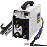
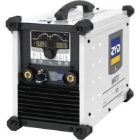
Only qualied personnel authorized by the manufacturer should perform the installation of the welding equipment. During set up, the operator must ensure that the machine is unplugged. It is recommended to use the welding cables supplied with the unit in order to obtain the optimum product settings. HARDWARE DESCRIPTION (FIG-1) The EXAGON 400 FLEX CC/CV is a three-phase or single-phase inverter welding source which, depending on its equipment, enables : - Electrode welding (MMA) - Semi automatic welding (MIG/MAG/ux cored wire) - Tungsten electrode welding (TIG) - Carbon electrode gouging The TIG process requires gas shielding (Argon). The MMA process can weld any type of electrode : rutile, basic, cellulosic, stainless and brass. The EXAGON 400 FLEX CC/CV can be equipped with a remote control or foot pedal.
1- Human-machine interface 5- Transport handles and lifting rings
4- Remote control cable connector
2- Active risk reduction system indicator (VRD) 14- Active remote control indicator
5- Disruption of normal operations indicator 17- Cellulosic electrode indicator
- This machine is tted with a 32A socket type EN 60309-1 which must only be used on a three-phase 400 V (50-60 Hz) four-wire earthed electrical installation. The absorbed eective current (I1e) is indicated on the device for optimum operating conditions. Check that the power supply and its safeguards (fuse and/or circuit breaker) are compatible with the electric current being used. In some countries, it may be necessary to change the plug to allow the use at maximum settings.
- The device is designed to operate on an electrical voltage of 208 to 525V +/-15%. The unit enters protection mode if the supply voltage is less than 185Vrms or greater than 600Vrms (a fault code will appear on the display).
- The start is done via an on / o switch (6) set to I, and the stop is done by switiching it to O. Attention ! Never disconnect the power supply when the machine is on.
The machine can work with generators as long as the auxiliary power matches these requirements : - The voltage must be alternating, with an RMS value of between 208 and 525V +/- 15%, and a peak voltage of less than 900V, - The frequency must be between 50 and 60 Hz. It is imperative to check these requirements as several generators generate high voltage peaks that can damage these machines.
USE WITH EXTENSION CABLES
All extension cables must have an adequate size and section, relative to the machine’s voltage . Use an extension that complies with national safety regulations. Input voltage Cross-section of the extension cable (Length < 45m) 208-380 V 10 mm² 380-525 V 4 mm² ELECTRODE WELDING (MMA AND MMA VERTICAL UP )
CONNECTIONS AND RECOMMENDATIONS
- Connect the cables, electrode holder and earth clamp in the connectors,
- Respect the welding polarities and intensities indicated on the electrodes boxes,
- Remove the electrode from the electrode holder when the machine is not in use. Rutile +9-9Basic ARC FORCE INDUCTANCE Cellulosic
VRD press 3spress 3s MMA The grey areas are not useful for this mode. Rutile +9-9Basic ARC FORCE INDUCTANCE Cellulosic
VRD press 3spress 3s MMA Vertical up The grey areas are not useful for this mode.19
EXAGON 400 FLEX CC/CV
MODE SELECTIONPress the button several times until the LED light switches on below the symbol or .The MMA vertical up mode adds a current pulse which makes vertical up welding easier.MAIN SETTINGS1. Selection of the electrode’s coating type : Selection of the electrode’s coating type by maintaining the button for more than 3 seconds until the LED switches on below the corresponding symbol.2. Welding intensity settings : Adjust the welding current using the main knob according to the electrode diameter and the type of assembly to be carried out. The current setpoint is indicated on the right side display.3. Arcforce settings : Adjust the arcforce level with the right side knob , a relative value from -9 to +9. The lower the arcforce, the softer the arc. The higher the arcforce, the higher the extra welding current . The default value is 0.WELDING PARAMETERSWELDING INTENSITY SETTINGS The following settings concern the intensity range that may be used depending on the electrode’s type and diameter . These ranges are quite large as they depend on the application and the welding position.Ø electrode (mm) Rutile E6013 (A) Basic E7018 (A) Cellulosic E6010 (A) 1.6 30-60 30-55 -2.0 50-70 50-80 -2.5 60-100 80-110 60-753.15 80-150 90-140 85-904.0 100-200 125-210 120-1605 150-290 200-260 110-1706.3 200-385 220-340 -ARCFORCE SETTINGS It is recommended to set the arc force in median position (0) to start the welding and adjust it according to the results and welding preferences. Note : the arcforce setting range is specic to the selected electrode type.ADVANCED SETTINGSRefer to the chapter « menu access » for more details regarding welding parameters.The two MMA modes and come with the following additional settings : : HotStart, level of the extra current at arc strike, expressed in percentage of the welding current. : Hotstart Time, duration of the extra current at arc strike, expressed in seconds. : Antisticking, active (On), the current will stop after 2 consecutive seconds of short circuit, inactive (O), the current will not stop, even in the event of long short circuit.In MMA vertical up mode , two extra settings are available : : Frequency, determines the number of pulses per second (Hz). : Percentage, determines the background/cold current expressed in percentage of the welding current. TUNGSTEN ELECTRODE WELDING WITH INERT GAS (TIG ) CONNECTIONS AND RECOMMENDATIONSTIG welding requires a torch as well as a gas bottle equipped with a regulator.Connect the earth clamp to the positive connector (+).Connect the torch’s earth cable to the negative plug (–).Connect the torch’s gas hose to the regulator’s output. Ensure that the torch is equipped and ready to weld, and that the consumables (Vise grip, ceramic gas nozzle, collet and collet body) are not damaged.20
MODE SELECTION Press the button several times until the LED light switches on below the symbol . WELDING STETTINGS
1. Welding intensity settings :
Adjust the welding current using the main knob according to the dia- meter and the type of assembly to be carried out. The current setpoint is indicated on the right side display.
2. Welding downslope settings :
Adjust the downslope duration using the secondary knob . The indica- tor shows the chosen settings, the right display indicates the precise downs- lope duration in seconds. Rutile
VRD press 3spress 3s The grey areas are not useful for this mode. ARC STRIKE / IGNITION : LIFT start : Using the torch, make contact between the electrode and the metal piece, then slightly lift the electrode to start the arc. WELD STOP / SWITCHING TO DOWNSLOPE : To stop the weld, slightly lift the torch, the intensity will gradually reduce (downslope). ASSISTANCE FOR SETTING UP AND SELECTING CONSUMABLES
L = 3 x d for a low current. L = 3 x d for a high current SEMI-AUTOMATIC MIG / MAG WELDING WITH VOLTAGE DETECTING WIRE FEEDER ( )
CONNECTIONS AND RECOMMENDATIONS
- Connect the earth clamp on the positive (+) or negative (-) terminal depending on the wire type (in general on the -)
- Connect the wire feeder on the connector using a male-female cable (NOMAD CABLE),
- Refer to the wire feeder’s user manual for the remaining connections.
MODE SELECTION AND SETTINGS
Press the button several times until the LED light switches on below the symbol .
1. Setting the welding voltage :
Adjust the welding voltage using the main knob depending on the work to be carried out. The voltage setpoint is indicated on the left side display.
2. Inductance settings :
Adjust the inductance level using the second knob , a relative value from -9 to +9. The lower the inductance level, the harder and more guiding the arc. The higher the inductance and the softer the arc with little splatter. Rutile
VRD press 3spress 3s The grey areas are not useful for this mode.
- Orient the clamp depending on the working position, make sure that the compressed air ows in the arc’s direction and not the other way around.
- Place a carbon electrode,
- Connect the compressed air to the gouging torch, The arc strike is easier : just make contact with the piece, and advance while pushing the electrodes towards the metal to be removed.21
Press the button several times until the LED light switches on below the symbol . Adjust the welding current using the main knob according to the electrode dia- meter , the current set point is shown on the right-hand display. Rutile0+9-9BasicARC FORCEINDUCTANCECellulosic601370186010 MMA press 3 sMIG TIGsetupmemoryGouging
VRD press 3spress 3s The grey areas are not useful for this mode.
DISPLAY CURRENT/VOLTAGE DURING WELDING
During welding, the machine measures and displays the welding current and voltage. After the weld, the average current and voltage values are displayed during 30 seconds, as soon as a knob or a button is pressed, the welding parameters are displayed.
SAVE AND LOAD WELDING SETTINGS
The current settings are automatically saved and loaded at start up. On top of the current settings, it is also possible to save and load 50 settings per each mode. The memory recalls : - Primary setting - Secondary setting (MMA, CV) - Secondary settings (MMA) Save new settings : - Maintain buttons and during 3 seconds. appears, release the buttons. - Turn one of the two knobs . Validate by pressing the button . - The display indicates a memory set (01 to 50) while blinking. - Turn the knob to select the memory set in which the desired settings will be saved. Validate by pressing the button
- The settings are saved / the menu exit is instantaneous. Load existing settings : - Maintain the buttons and during 3 seconds. appears, release the buttons. - Turn one of the two knobs to display . Validate by pressing the button . - The display indicates a memory set (01 to 50) while blinking. - Turn one of the two knobs to select the memory set containing the desired settings to load. Validate by pressing the button . The settings are loaded / the menu exit is instantaneous. REMOTE CONTROL The remote control option or pedal option has not been designed to operate on the EXAGON when the EXATIG (ref. 013780) is connected. The current can be adjusted by using the potentiometer torch (ref. 047877) connected to the EXATIG which controls the EXAGON’s current level.
CONNECTIONS AND RECOMMENDATIONS
The remote control works in all modes. The remote control acts on the primary settings of the current process (MMA and TIG, voltage and gouging). Connections :
Foot pedal selection. Remote control with potentiometer selection. The remote ontrol type selection is done with the two knobs, the validation is done with the button
The LED (FIG-2, n°14) switches on. It is possible to activate / deactivate the remote control without having to physically unplug the remote control. Press the button , for 3 seconds, the LED (FIG-2, n°14) indicates the state of the remote control (LED on = remote control on).22
EXAGON 400 FLEX CC/CV
Operations :• Manual remote control (GYS product ref. 045675).The manual remote control can adjust : - the current from 50% to 100% of the set intensity using the main knob. The displayed current setpoint matches the potentiometer position. The displayed current setpoint becomes a 100% of the settings when the main knob is turned towards the machine’s keypad. - from minimum to the maximum of the voltage range (then the main knob has no eect). The voltage display shows the remote control variation.
- Foot pedal (option ref. 045682) :The pedal control can adjust : - the current from 50% to 100% of the set intensity using the main knob. The displayed current setpoint corresponds to a 100% of the value. Connectors Beyond the manual remote control and the pedal, it is possible to create you own connectors using the optional male socket (ref. 045699). For the cabling layout, please see the diagram below utiliser a 10 kΩ potentiometer).
ref. 045699 External view Electric diagram according to the remote control type. COOLING FAN To minimise sound and dust aspiration, the station integrates a controlled fan system. The fan’s rotation speed depends on the temperature and the machine’s settings. LOCKING CONTROLS That feature can lock the knobs and keypad to prevent accidental changes in the settings.Operation : Press the button for 3 seconds, the display shows and goes back to current display. The LED (FIG-2, n°11) switches on. No button is enabled, the secondary knob is disabled, the main knob can adjust the value at +/- of the percentage, dened by the «tolerance» setting (see chapter «Access to menus»). To unlock the commands, press the button for 3 seconds, the display shows then goes back to current display. The LED (FIG-2, n°11) switches o.
+ x 3s 1s 1s 1s.........Load settings and menu exitSave settings and menu exitValidate tolerance settings and back to root menuReset all settings for all processesOnly for MMA and Vertical up MMA Current process settings menuExit settings menuWelding MMI outputButtons' releaseCurrent value23
Back to Setup menu Hot StartHot Start time AntiStickingFrequency(MMA vertical up)Perrcentage(MMA vertical up) Validate current settingReset current settingCurrent valueCurrent valueCurrent valueCurrent valueCurrent value ACTIVATION OF THE VRD FUNCTION (VOLTAGE REDUCTION DEVICE) The voltage reduction device (or VRD) is used to protect the welder. The welding current is only delivered when the electrode is in contact with the workpiece (low resistance). As soon as the electrode is removed, the VRD function lowers the voltage considerably. By default, the voltage reduction device is deactivated. In order to activate it, the user must open the product and complete the following proce- dure:1. DISCONNECT THE PRODUCT FROM THE POWER SUPPLY AND WAIT 5 MINUTES FOR SAFETY.2. Remove the side of the power source (see page at the end of the manual).3. Locate the control board and the VRD switch (see page at the end of the manual).4. Toggle the switch to the ON position.5. The VRD function is activated.6. Reinstall the side panel of the unit.7. The VRD icon on the interface (HMI) will be lit.To deactivate the VRD function, simply ip the switch back to the opposite position. TROUBLESHOOTING This device integrates a default management system. In the event of a default, error messages may be displayed.Error code Signication CAUSES SOLUTIONS Thermal protection.Operating factor exceeded. Ambient temperature above 40°C. Air inlets blocked.Wait for the light to go out before resuming welding. Respect the duty cycle and ensure good ventilation. Use of the optional dust lter reduces the duty cycle. Undervoltage fault Voltage below 185VacHave your electrical installation checked by a quali-ed electrician. The voltage between phases must be between 185Ve and 600Ve. Overvoltage fault Voltage over 600Vac Primary connector faultThe primary connector is disconnected or faulty.Have the wiring of the primary connector checked by qualied personnel. Power relay control fault. The power relay could not be closed.Have the relay control wiring checked by qualied personnel. All operations requiring the removal of the machine’s cover and checking the electrical systems must be done by a qualied technician.24
WARRANTY The warranty covers faulty workmanship for 2 years from the date of purchase (parts and labour). The warranty does not cover:
- Damages due to misuse (power supply error, dropping of equipment, disassembling).
- Environment related failures (pollution, rust, dust). In case of failure, return the unit to your distributor together with: - The proof of purchase (receipt etc ...) - A description of the fault reported25
WAARSCHUWING - VEILIGHEIDSINSTRUCTIES
INTERFACE HUMANE MACHINE (IHM) (FIG-2)
Patin Angle 3 points / 3-point angle skate
Ensure the machine is unplugged from the mains, and then wait 2 minutes.
Warning ! Read the user manual before use.
Undulating current technology based source delivering direct curent.
Suitable for welding in an environment with an increased risk of electric shock. However this a machine should not placed in such an environment.
Direct welding current
Open circuit voltage
Duty cycle according to standard EN 60974-1 (10 minutes – 40°C).
Corresponding conventional welding current
Conventional voltage in corresponding loads.
Three-phase power supply 50 or 60Hz
Maximum rated power supply current (effective value).
Maximum effective power supply current.
Device complies with europeans directives, The EU declaration of conformity is available on our website (see cover page).
Equipment in compliance with British requirements. The British Declaration of Conformity is available on our website (see home page).
Equipment in conformity with Moroccan standards. The declaration Cم (CMIM) of conformity is available on our website (see cover page).
The device is compliant with standard EN60974-1 and EN60971-10 class A device.
This hardware is subject to waste collection according to the European directives 2012/19/EU. Do not throw out in a domestic bin !
This product should be recycled appropriately
EAEC Conformity marking (Eurasian Economic Community).
Temperature information (thermal protection)