Multiweld 180MC - Welding machine GYS - Free user manual and instructions
Find the device manual for free Multiweld 180MC GYS in PDF.
| Product type | Semi-automatic MIG/MAG, flux-cored wire and MMA welding machine |
| Brand | GYS |
| Model | Multiweld 180MC |
| Power supply | Single-phase 230 V - 50/60 Hz - CEE7/7 plug 16 A |
| Max welding current | 180 A |
| Welding processes | MIG/MAG, flux-cored wire (No Gas), MMA (coated electrode) |
| Weldable materials | Steel, stainless steel, aluminum |
| Wire diameters | Steel/stainless: 0.6 / 0.8 mm; Flux-cored: 0.9 mm; Aluminum: 0.8 / 1.0 mm |
| Shielding gas | Steel: Ar+CO₂ (8-12 L/min); Stainless: 2% CO₂ mix; Aluminum: Pure argon (20-30 L/min); Max pressure 0.5 MPa (5 bar) |
| Protection degree | IP21 |
| EMC class | Class A |
| Operating temperature | -10 to +40 °C |
| Storage temperature | -20 to +55 °C |
| Max altitude | 1000 m |
| Max humidity | 50% at 40°C / 90% at 20°C |
| Power cable length | 2 m |
| Cooling type | Temperature-controlled fan |
| Special functions | Anti-stick (MMA), wire speed adjustment, voltage, inductance |
| Display | Digital displays |
| Spool support | 200 / 300 mm |
| Weight (approx) | 18 kg |
| Dimensions (L x W x H) approx | 40 x 30 x 30 cm |
Frequently Asked Questions - Multiweld 180MC GYS
User questions about Multiweld 180MC GYS
0 question about this device. Answer the ones you know or ask your own.
Ask a new question about this device
Download the instructions for your Welding machine in PDF format for free! Find your manual Multiweld 180MC - GYS and take your electronic device back in hand. On this page are published all the documents necessary for the use of your device. Multiweld 180MC by GYS.
USER MANUAL Multiweld 180MC GYS
natural_image
Line drawing of a portable electronic device with control panel, buttons, and wiring (no text or symbols)FR 2-9 / 74-84
EN 10-17 / 74-84
DE 18-25 / 74-84
ES 26-33 / 74-84
RU 34-41 / 74-84
NL 42-49 / 74-84
IT 50-57 / 74-84
PL 58-65 / 74-84
CZ 66-73 / 74-84
MULTIWELD 180M-C
INSTALLATION – FONCTIONNEMENT PRODUIT
ANOMALIES, CAUSES, REMEDES
Read and understand the following safety recommendations before using or servicing the unit. Any change or servicing that is not specified in the instruction manual must not be undertaken.
The manufacturer is not liable for any injury or damage due to non-compliance with the instructions featured in this manual. In the event of problems or uncertainty, please consult a qualified person to handle the inspection properly.
ENVIRONMENT
This equipment must only be used for welding operations in accordance with the limits indicated on the descriptive panel and/or in the user manual. The operator must respect the safety precautions that apply to this type of welding. In case of inedaquate or unsafe use, the manufacturer cannot be held liable for damage or injury.
This equipment must be used and stored in a place protected from dust, acid or any other corrosive agent. Operate the machine in an open, or well-ventilated area.
Operating temperature:
Use between -10 and +40°C (+14 and +104°F).
Store between -20 and +55°C (-4 and 131°F).
Air humidity:
Lower or equal to 50% at 40°C (104°F).
Lower or equal to 90% at 20°C (68°F).
Altitude:
Up to 1000 meters above sea level (3280 feet).
PROTECTION OF THE INDIVIDUALS
Arc welding can be dangerous and can cause serious and even fatal injuries.
Welding exposes the user to dangerous heat, arc rays, electromagnetic fields, noise, gas fumes, and electrical shocks. People wearing pacemakers are advised to consult with their doctor before using this device.
To protect oneself as well as the other, ensure the following safety precautions are taken:

In order to protect you from burns and radiations, wear clothing without cuffs. These clothes must be insulated, dry, fireproof and in good condition, and cover the whole body.

Wear protective gloves which guarantee electrical and thermal insulation.

Use sufficient welding protective gear for the whole body: hood, gloves, jacket, trousers... (varies depending on the application/operation). Protect the eyes during cleaning operations. Do not operate whilst wearing contact lenses. It may be necessary to install fireproof welding curtains to protect the area against arc rays, weld spatters and sparks.
Inform the people around the working area to never look at the arc nor the molten metal, and to wear protective clothes.

Ensure ear protection is worn by the operator if the work exceeds the authorised noise limit (the same applies to any person in the welding area).
Stay away from moving parts (e.g. engine, fan...) with hands, hair, clothes etc...
Never remove the safety covers from the cooling unit when the machine is plugged in - The manufacturer is not responsible for any accident or injury that happens as a result of not following these safety precautions.
The pieces that have just been welded are hot and may cause burns when manipulated. During maintenance work on the torch or the electrode holder, you should make sure it's cold enough and wait at least 10 minutes before any intervention. The cooling unit must be on when using a water cooled torch in order to ensure that the liquid does not cause any burns.
ALWAYS ensure the working area is left as safe and secure as possible to prevent damage or accidents.
WELDING FUMES AND GAS

The fumes, gases and dust produced during welding are hazardous. It is mandatory to ensure adequate ventilation and/or extraction to keep fumes and gases away from the work area. An air fed helmet is recommended in cases of insufficient air supply in the workplace.
Check that the air intake is in compliance with safety standards
pieces of metal containing lead, cadmium, zinc, mercury or beryllium can be extremely toxic. The user will also need to degrease the workpiece before welding.
Gas cylinders must be stored in an open or ventilated area. The cylinders must be in a vertical position secured to a support or trolley. Do not weld in areas where grease or paint are stored.
FIRE AND EXPLOSIONS RISKS

Protect the entire welding area. Compressed gas containers and other inflammable material must be moved to a minimum safe distance of 11 meters.
A fire extinguisher must be readily available.
Be careful of spatter and sparks, even through cracks. It can be the source of a fire or an explosion.
Keep people, flammable objects and containers under pressure at a safe distance.
Welding of sealed containers or closed pipes should not be undertaken, and if opened, the operator must remove any inflammable or explosive materials (oil, petrol, gas...).
Grinding operations should not be directed towards the device itself, the power supply or any flammable materials.
GAS BOTTLE

Gas leaking from the cylinder can lead to suffocation if present in high concentrations around the work area.
Transport must be done safely: Cylinders closed and product off. Always keep cylinders in an upright position securely chained to a fixed support or trolley.
Close the bottle after any welding operation. Be wary of temperature changes or exposure to sunlight.
Cylinders should be located away from areas where they may be struck or subjected to physical damage.
Always keep gas bottles at a safe distance from arc welding or cutting operations, and any source of heat, sparks or flames.
Be careful when opening the valve on the gas bottle, it is necessary to remove the tip of the valve and make sure the gas meets your welding requirements.
ELECTRIC SAFETY

The machine must be connected to an earthed electrical supply. Use the recommended fuse size. An electrical discharge can directly or indirectly cause serious or deadly accidents.
Do not touch any live part of the machine (inside or outside) when it is plugged in (Torches, earth cable, cables, electrodes) because they are connected to the welding circuit.
Before opening the device, it is imperative to disconnect it from the mains and wait 2 minutes, so that all the capacitors are discharged. Do not touch the torch or electrode holder and earth clamp at the same time.
Damaged cables and torches must be changed by a qualified and skilled professional. Make sure that the cable cross section is adequate with the usage (extensions and welding cables). Always wear dry clothes in good condition, in order to be insulated from the electrical circuit. Wear insulating shoes, regardless of the environment in which you work in.
EMC CLASSIFICATION

These Class A devices are not intended to be used on a residential site where the electric current is supplied by the public network, with a low voltage power supply. There may be potential difficulties in ensuring electromagnetic compatibility on these sites, because of the interferences, as well as radio frequencies.

This equipment does not comply with IEC 61000-3-12 and is intended to be connected to private low-voltage systems interfacing with the public supply only at the medium- or high-voltage level. On a public low-voltage power grid, it is the responsibility of the installer or user of the device to ensure, by checking with the operator of the distribution network, which device can be connected.
This equipment complies with the IEC 61000-3-11 standard.
ELECTROMAGNETIC INTERFERENCES
The electric currents flowing through a conductor cause electrical and magnetic fields (EMF). The welding current generates an EMF field around the welding circuit and the welding equipment.
medical implants. For example, access restrictions for passers-by or an individual risk evaluation for the welders.
All welders should take the following precautions in order to minimise exposure to the electromagnetic fields (EMF) generated by the welding circuit::
- position the welding cables together – if possible, attach them;
- keep your head and torso as far as possible from the welding circuit;
- never enroll the cables around your body;
- never position your body between the welding cables. Hold both welding cables on the same side of your body;
- connect the earth clamp as close as possible to the area being welded;
- do not work too close to, do not lean and do not sit on the welding machine
- do not weld when you're carrying the welding machine or its wire feeder.

People wearing pacemakers are advised to consult their doctor before using this device.
Exposure to electromagnetic fields while welding may have other health effects which are not yet known.
RECOMMANDATIONS TO ASSES THE AREA AND WELDING INSTALLATION
Overview
The user is responsible for installing and using the arc welding equipment in accordance with the manufacturer's instructions. If electromagnetic disturbances are detected, it is the responsibility of the user of the arc welding equipment to resolve the situation with the manufacturer's technical assistance. In some cases, this remedial action may be as simple as earthing the welding circuit. In other cases, it may be necessary to construct an electromagnetic shield around the welding power source and around the entire piece by fitting input filters. In all cases, electromagnetic interferences must be reduced until they are no longer bothersome.
Welding area assessment
Before installing the machine, the user must evaluate the possible electromagnetic problems that may arise in the area where the installation is planned.
In particular, it should consider the following:
a) the presence of other power cables (power supply cables, telephone cables, command cable, etc...) above, below and on the sides of the arc welding machine.
b) television transmitters and receivers ;
c) computers and other hardware;
d) critical safety equipment such as industrial machine protections;
e) the health and safety of the people in the area such as people with pacemakers or hearing aids;
f) calibration and measuring equipment
g) the isolation of the equipment from other machinery.
The user will have to make sure that the devices and equipments that are in the same room are compatible with each other. This may require extra precautions;
h) make sure of the exact hour when the welding and/or other operations will take place.
The surface of the area to be considered around the device depends on the building's structure and other activities that take place there. The area taken in consideration can be larger than the limits determined by the companies.
Welding area assessment
Besides the welding area, the assessment of the arc welding systems intallation itself can be used to identify and resolve cases of disturbances. The assessment of emissions must include in situ measurements as specified in Article 10 of CISPR 11. In situ measurements can also be used to confirm the effectiveness of mitigation measures.
RECOMMENDATION ON METHODS OF ELECTROMAGNETIC EMISSIONS REDUCTION
a. National power grid: The arc welding machine must be connected to the national power grid in accordance with the manufacturer's recommendation. If interferences occur, it may be necessary to take additional preventive measures such as the filtering of the power supply network. Consideration should be given to shielding the power supply cable in a metal conduit. It is necessary to ensure the shielding's electrical continuity along the cable's entire length. The shielding should be connected to the welding current's source to ensure good electrical contact between the conduct and the casing of the welding current source.
b. Maintenance of the arc welding equipment : The arc welding machine should be submitted to a routine maintenance check according to the manufacturer's recommendations. All accesses, service doors and covers should be closed and properly locked when the arc welding equipment is on. The arc welding equipment must not be modified in any way, except for the changes and settings outlined in the manufacturer's instructions. The spark gap of the arc start and arc stabilization devices must be adjusted and maintained according to the manufacturer's recommendations.
c. Welding cables : Cables must be as short as possible, close to each other and close to the ground, if not on the ground.
d. Electrical bonding : consideration should be given to bonding all metal objects in the surrounding area. However, metal objects connected to the workpiece increase the risk of electric shock if the operator touches both these metal elements and the electrode. It is necessary to insulate the operator from such metal objects.
e. Earthing of the welded part : When the part is not earthed - due to electrical safety reasons or because of its size and its
location (which is the case with ship hulls or metallic building structures), the earthing of the part can, in some cases but not systematically, reduce emissions. It is preferable to avoid the earthing of parts that could increase the risk of injury to the users or damage other electrical equipment. If necessary, it is appropriate that the earthing of the part is done directly, but in some countries that do not allow such a direct connection, it is appropriate that the connection is made with a capacitor selected according to national regulations.
f. Protection and plating : The selective protection and plating of other cables and devices in the area can reduce perturbation issues. The protection of the entire welding area can be considered for specific situations.
TRANSPORT AND TRANSIT OF THE WELDING MACHINE

This welding power source comes equipped with a top strap so that it can be carried by hand. Be careful not to underestimate its weight. The strap is not intended to be used to suspend or hang the device.
Do not use the cables or torch to move the welding power source. It should be moved in an upright position. Do not carry or transport the power source overhead of people or objects. It is advisable to remove the wire-feed spool before lifting or transporting the welding power source.
EQUIPMENT INSTALLATION
- Put the machine on the floor (maximum incline of 10^ ).
- Ensure the work area has sufficient ventilation for welding, and that there is easy access to the control panel.
- The machine must not be used in an area with conductive metal dusts.
- The machine must be placed in a sheltered area away from rain or direct sunlight.
- The machine protection level is IP21, which means :
- Protection against access to dangerous parts from solid bodies of a ≥12.5mm diameter and,
- Protection against vertically falling drops.
The power cables, extensions and welding cables must be fully uncoiled to prevent overheating.

The manufacturer does not incur any responsibility regarding damages to both objects and persons that result from an incorrect and/or dangerous use of the machine.

Stray welding currents/voltages may destroy earth conductors, damage electrical equipment or cause components to warm up which may cause a fire.
- All welding connections must be firmly secured, check regularly!
- Check that the metal piece fixation is strong and without any electrical problems!
- Attach or hang all the electrically conductive elements, such as the trolley in order to insulate them.
- Do not place any electrical equipment such as drills on top of the welding machine without insulating them!
- Always place welding torches or electrodes holders on an insulated surface when they're not in use!
MAINTENANCE / RECOMMENDATIONS


- Maintenance should only be carried out by a qualified person. Annual maintenance is recommended.
- Ensure the machine is unplugged from the mains, and wait for two minutes before carrying out maintenance work. DANGER High Voltage and Currents inside the machine.
- Remove the casing 2 or 3 times a year to remove any excess dust. Take this opportunity to have the electrical connections checked by a qualified person, with an insulated tool.
- Regularly check the condition of the power supply cable. If the power cable is damaged, it must be replaced by the manufacturer, its after sales service or an equally qualified person.
- Ensure the ventilation holes of the device are not blocked to allow adequate air circulation.
- Do not use this equipment to thaw pipes, to charge batteries, or to start any engine.
INSTALLATION - USING THE PRODUCT
Only experienced personnel, authorised by the manufacturer, may carry out the machine's set-up. During set-up, ensure that the power source is unplugged from the mains. It is recommended to use the welding cables supplied with the unit in order to obtain the optimum product settings.
DESCRIPTION
Thank you for choosing this machine. To get the best use from your machine, please read the following carefully: The MULTIWELD range are semi-automatic MIG/MAG, MMA and flux cored wire welding stations. They are manual settings machine, with the help of the table printed on the product. They are recommended for welding steel, stainless steel and aluminium.
POWER SUPPLY
This machine is fitted with a 16A socket type CEE7/7 which must be connected to a single-phase 230V (50 - 60 Hz) power supply fitted with three wires and one earthed neutral. The absorbed current (I1eff) is indicated on the device at maximum usage. Check that the power supply and its protection (fuse and/or circuit breaker) are compatible with the current needed for use. In some countries, it might be necessary to change the plug to allow maximum performance. The device must be installed so that the mains socket is accessible.
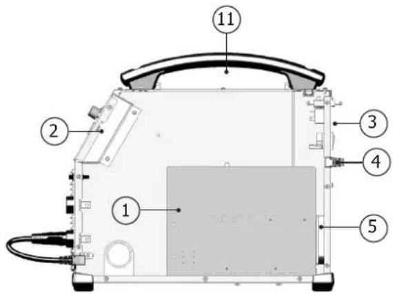
MACHINE DESCRIPTION (FIG I)
1- Adjustment of welding settings (wire speed, welding voltage and inductance). 6- Power Cable (2 m)
2- Switch MIG/ MMA 7- Power switch
3- European standard torch connection. 8- Reel adaptor 200/300mm
4- Connectors 9- Digital displays
5- Polarity reversal cable
USING EXTENSION LEADS
All extension leads must be of a size and cross-section appropriate for the equipment's voltage. Use an extension lead that complies with national safety regulations.
| Input voltage Extension-lead length (<45 m) |
| 230 V - 1~ 1.5 mm ^2 |
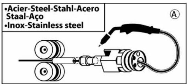
SEMI-AUTOMATIC WELDING FOR STEEL / STAINLESS STEEL (MAG MODE)
Set the voltage output and the wire speed according to the thickness of the weld piece, following the instructions/recommendations printed on the side of the machine.
The MULTIWELD can weld Steel wire 0.6/0.8mm, and Stainless Steel of 0.8mm.
The machine is fitted with ∅ 0.8mm Steel or Stainless Steel rollers. The contact tube, the groove of the roller and the sleeve of the torch are all compatible with 0.8mm wire. Should you wish to weld 0,6 wire, use a torch of maximum 3m long. The contact tip must be changed (fig IV-D) as well as the wire feeder's roller that must be replaced by an optional reference (042339) with a 0.6 diameter groove. In this case, the position in such a way to observe 0.6. For use with Steel, the gas requirement is argon + CO2. (Ar+CO2). The proportion of CO2 required will vary depending on the use. For Stainless Steel, use the combination of 2% CO2 for specific gas requirements, please contact your gas distributor. The gas flow in steel is between 8 and 12 Litres/minute depending on the environment. Maximum gas pressure : 0.5 MPa (5 bars).
SEMI-AUTOMATIC WELDING FOR ALUMINIUM (MIG MODE)
Set the voltage output and the wire speed according to the thickness of the weld piece, following the instructions/recommendations printed on the side of the machine.
The MULTIWELD can be equipped to weld with aluminium wire ∅ 0,8 or 1,0 (fig II-B).
For use with aluminium, the gas requirement is pure argon (Ar). For the specific gas requirements please contact your distributor. The gas flow in Aluminium is between 20 and 30 Litres/minute depending on the environment, and the experience of the welder. Maximum gas pressure : 0.5 MPa (5 bars).
Below are the differences between welding with Steel and Aluminium :
- Specific rollers are needed for welding with Aluminium.
- Adjust the pressure of the drive rolls to prevent the wire being crushed.
- Only use a capillary tube for welding with Steel or Stainless Steel.
- Use a special Aluminium Torch with a teflon sheath to reduce friction.
DO NOT cut the sheath close to the joint, it is used to guide the wire from the the rollers. - Contact Tube : Use a special aluminium contact tube specific to the diameter of wire being used.
GASLESS WIRE WELDING
Set the voltage output and the wire speed according to the thickness of the weld piece, following the instructions/recommendations printed on the side of the machine.
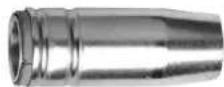
The MULTIWELD can weld gasless wire up to 0.9mm, if the polarity is reversed respecting a maximum pressure of 5Nm. For parameters of use, please refer to the instructions indicated on page 75. Welding gasless wire with a standard nozzle can lead to overheating and deterioration of the torch. It is recommended to use a "No Gas" nozzle (ref. 041868), or remove the genuine nozzle (Fig. III).
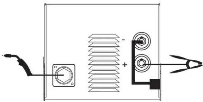
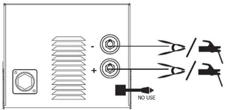
ELECTRODE WELDING
- The reverse polarity cable must be disconnected in MMA (stick welding) mode in order to connect the electrode holder and earth clamp. Connect the electrode holder and earth clamp as indicated on the electrode packaging.
- Respect the basic rules of welding.
- This device has 1 feature specific to Inverter machines :
- Anti-Sticking: Enables easy removal of the electrode from the metal. The anti-sticking feature, after its start, requires approximately a 3 seconds delay before resuming normal welding operations.
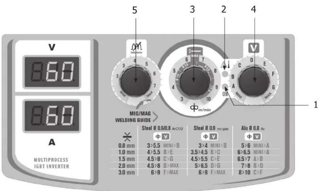
SETTINGS PANEL (FIG V)
| 1 | · Green light «ON»: when the machine is switched on the light turns on.· In case of power failure, the green light goes off but the device remains powered while the power cable is unplugged. |  ON ON |
| 2 | Orange light :· Over-temperature: in such a case you shall wait a few minutes, the light will turn off and the machine will start again.· Over-current on primary circuit: in such a case you shall switch off the machine (with the main switch) and switch on. |  |
| 3 | · Left button:- MIG / MAG Welding : Adjust the wire feeder speed up to maximum speed.- MMA welding : Adjust the welding current. | 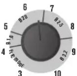 [cc4k] m/min [cc4k] m/min |
| 4 | · Right button:- Adjust the voltage reference up to the maximum value. | 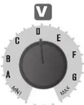 |
| 5 | Welding arc dynamic potentiometer : Can manually adjust the arc dynamic.MINI to MAX settings : Hard arc to soft arc. | 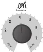 |
| AdvicesThe wire speed adjustment is often determined « with the assistance of sound »: the arc must be stable and have a low crackling.If the speed is too low, the arc is not continuous.If the speed is too high, the arc crackles and the wire pushes back the torch.The inductance adjustment is done according to the welder's preferences :The lower the inductance, the more the arc will be hard and guiding.The higher the inductance and the softer the arc with little splatter. | ||
PROCESS OF REELS AND TORCHES ASSEMBLY (FIG IV)
- Remove the contact tube and its support (fig D), and the nozzle (fig E) from the torch.
Fig A :
- Position the wire reel on the reel support :
- Adjust the reel brake (1) to avoid reel movement tangling the wire when welding stops. Be careful not to tighten too much.
For a 200mm wire reel tighten the reel to the maximum. The adaptor (4) is only to be used for a 200mm reel.
Fig B :
- The rollers supplied are double groove steel rollers (0.8 and 0.9).
For 0.8mm steel wire, use the V shaped groove. For flux cored wire, remove and reverse the roller to use the 0.9mm groove.
For 0.8mm aluminium wire, remove and replace the roll with a model specifically designed for aluminium with a U shaped groove (not included).
Fig C :
To select the adjustment of the drive rollers.
- Loosen the drive roller knob (3) as far as possible and insert the wire, tighten the knob again slightly.
- Start the motor by pressing the trigger of the torch.
- Tighten the knob whilst pressing the trigger until the wire starts to move.
Nb : When welding with Aluminium, use the minimum possible pressure to avoid crushing the wire
- Leave about 5cm of wire out of the torch, then put the contact tube (fig. D), and the nozzle (fig. E) adapted to the wire to be used at the extremity.
GAS COUPLING
- Connect a pressure regulator to the gas bottle. Connect the welding machine (fig. F) using the pipes supplied, and place the two clamps to avoid leakages.
- Set the gas flow by adjusting the dial located on the pressure regulator.
NB : to help facilitate the adjustment of the gas flow, operate the drive rollers by pressing the trigger of the torch (ensure that the drive roller is completely loose so the wire is not fed through).
This procedure does not apply to «Gasless» welding mode.
RECOMMENDED COMBINATIONS
| (mm) | Current (A) ∅ Wire (mm) ∅ Nozzle (mm) Flow rate | L/min | ||
| MIG | 0.8-2 20-100 0.8 | 12 10-12 | ||
| 2-4 100-200 1.0 | 12-15 12-15 | |||
| MAG | 0.6-1.5 15-80 0.6 | 12 8-10 | ||
| 1.5-3 80-150 0.8 | 12-15 10-12 | |||
| 3-8 150-300 | 1.0/1.2 | 15-16 12-15 |
RISK OF INJURY DUE TO MOVING PARTS

The wire feeders contain moving parts that may catch hand, hair, clothes or tools which can lead to injuries! Take extra care.
- Do not lay a hand to swivel or moving components or parts to the drive!
- Ensure that the housing covers or protective covers remain closed during operation!
- Do not wear gloves when threading the filler wire and changing the filler wire spool.
ADVICE & THERMAL PROTECTION
This device is equipped with a ventilator regulated by the inside temperature. When the machine's thermal protection is activated, it will not deliver any current. Orange light (Fig-V-2) will turn on until the temperature of the machine has returned to normal.
- Do not block/cover the ventilation holes, ensure free flow of air.
- Whilst in thermal protection mode leave the machine plugged into the mains after welding to allow it to cool.
General observations :
• Always respect the basic rules of welding.
• Always work in an adequately ventilated area.
- Do not work on a damp surface.
TROUBLESHOOTING
| SYMPTOMS | POSSIBLE CAUSES | REMEDIES |
| The welding wire speed is not constant. | Debris is blocking up the opening. | Clean out the contact batch or change it and replace the anti-adherence product.Ref.041806. |
| The wire skids in the rollers. | • Control the roller pressure or replace it.• Wire diameter non-compatible with roller• Covering wire guide in the torch non-compatible. | |
| The wire-feeder motor doesn't operate. | Reel or roller brake too tight. Release the brake and rollers. | |
| Electrical supply problem. | Check that the power switch is in the "On" position. | |
| Bad wire feeding. | Covering wire guide dirty or damaged. | Clean or replace |
| The drive roller is too loose | Tighten the drive roller knob | |
| Reel brake too tight | Release the brake | |
| No welding current | Bad connection to the main supply. | Check the mains connection and look if the plug is fed by 230 V (1PH) power socket. |
| Bad earth connection. | Check the earth cable (connection and clamp condition). | |
| Torch trigger inoperative. | Check the torch trigger / replace torch | |
| SYMPTOMS POSSIBLE CAUSES REMEDIES | ||
| The wire jams (after the rollers) | Guide wire sheath crushed. Check the sheath and torch body. | |
| Wire jammed in the torch Clean or replace. | ||
| No capillary tube. Check the presence of capillary tube. | ||
| Wire speed too fast Reduce the wire speed | ||
| The welding bead is porous | The gas flow rate is not sufficient. | Adjust flow range 15 to 20 L / min. |
| Clean the working metal. | ||
| Gas bottle empty. Replace it. | ||
| Gas quality unsatisfactory. Replace it. | ||
| Air flow or wind influence. Prevent drafts, protect welding area. | ||
| Gas nozzle dirty. Clean or replace the gas nozzle. | ||
| Poor quality wire. Use suitable WIRE for MIG-MAG welding. | ||
| Surface to weld in bad condition. (rust, etc...) Clean the metal before welding. | ||
| Very important flashing particules. | Arc voltage too low or too high. See welding settings. | |
| Bad earth connection. Adjust the earth cable for a better connection. | ||
| Insufficient gas flow. Adjust the gas flow. | ||
| No gas flow at the end of the torch. | Bad gas connection. | Check the gas connection at the welding machine. Check the gas regulator and the solenoid valves. |
WARRANTY
The warranty covers faulty workmanship for 2 years from the date of purchase (parts and labour).
The warranty does not cover:
- Transit damage.
- Normal wear of parts (eg. : cables, clamps, etc..).
- Damages due to misuse (power supply error, dropping of equipment, disassembling).
- Environment related failures (pollution, rust, dust).
In case of failure, return the unit to your distributor together with:
- The proof of purchase (receipt etc ...)
- A description of the fault reported.

WAARSCHUWINGEN - VEILIGHEIDSINSTRUCTIES
ALGEMENE INSTRUCTIES

BESCHRIJVING VAN HET APPARAAT (FIG I)
RYZYKO POŻARU I WYBUCHU

text_image
Labeled diagram of a device rear panel with numbered components for identification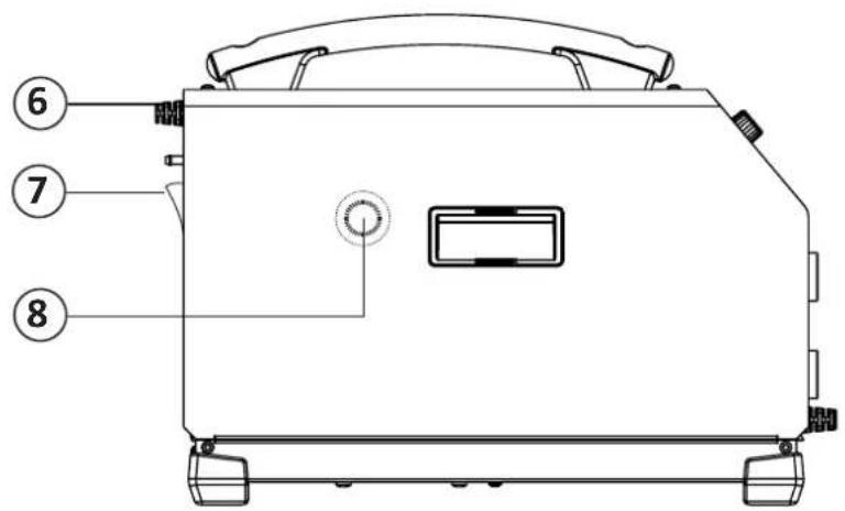
text_image
⑥ ⑦ ⑧II
text_image
•Acier-Steel-Stahl-Acero Staal-Aço •Inox-Stainless steel A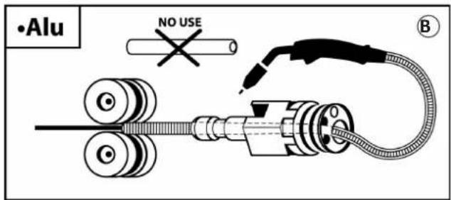
text_image
•Alu NO USE BMIG-MAG
natural_image
Pure electrical circuit lines without any symbols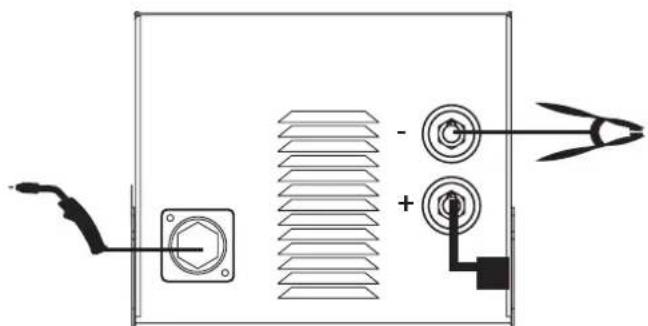
natural_image
Pure electrical circuit lines without any symbolsGASNO GAS
MMA
FR - Vérifier la polarité de l'électrode sur l'emballage.
EN - Check the electrode polarity on the packaging.
DE - Beachten Sie die auf der Elektrodenverpackung beschriebenen Angaben zur Polarität.
ES – Compruebe la polaridad del electrodo sobre el embalaje.
RU – Проверить полярность электрода на упаковке.
NL - Controleer de polariteit van de elektrode aangegeven op de verpakking.
IT - Verificare la polarità dell'elettrodo sulla confezione.
PL -Sprawdzić polaryzację elektrody na opakowaniu.
CZ -Zkontrolujte polaritu elektrody uvedena na obalu.
text_image
Diagram showing a device panel with screw, indicator lights, and a 'NO USE' label pointing to three labeled components.text_image
Technical diagram showing mechanical assembly with labeled parts A, B, and C, including a circular component and three close-up views.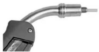
natural_image
Close-up of a metallic tool with curved metal components (no visible text or symbols)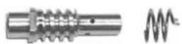
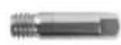
D
E
V
text_image
V 8.60 8.60 A MULTIPROCESS IGBT INVERTER 5 3 2 4 MIG/MAG WELDING GUIDE Steel Ø 0.6/0.8 ArCO2 Φ V 0.8 mm 1.0 mm 1.5 mm 2.0 mm 3.0 mm Steel Ø 0.9 no gas Φ V 3>5.5 MINI>B 4>5.5 B>E 4.5>8 C>G 4.5>8 D>MAX 6>9 F>MAX Steel Ø 0.9 Φ V 3>4 MINI>B 3.5>4.5 B>C 4.5>5.5 C>E 5>6.5 D>G 6>9 F>MAX Alu Ø 0.8 Ar Φ V 5>6 MINI>A 6>6.5 MINI>A 6.5>7 A>B 7>8 B>D 8>10 C>FPIÈCES DE RECHANGE / SPARE PARTS / ERSATZTEILE / PIEZAS DE REPUESTO / ЗАПАСНЫЕ ЧАСТИ / RESERVE ONDERDELEN / PEZZI DI RICAMBIO / CZĘSCI ZAMIENNE / NAHRÁDNÍ DÍLY
text_image
Labeled diagram of a device interior with numbered components for identification
text_image
Technical diagram of a mechanical device with numbered components for identification| 1 | Carte principale / Main circuit board / Hauptplatine / Tarjeta principal / Основная плата / Hoofd printplaat / Carta principale / Płyta główna / Hlavní deska | B4111 |
| 2 | Carte affichage / Display card / Anzeigeplatine /Placa frontal (display) / Плата отображения на дисплее / Display plaat / Scheda display / Karta graficzna / Deska indikací | 53498 |
| 3 | Interrupteur /Switch / An/ Aus- Schalter /Interruptor / Переключатель / Schakelaar / Interruttore / Wyłącznik / Spínač zap./vyp. | 53546 |
| 4 | Câble d'alimentation / Power lead / Netzstromkabel / Cable de alimentación / Шнур питания / Voedingskabel / Cavo di rifornimento / Kabel zasilania / Napájecí kabel | 21468 |
| 5 | Ventilateur / Fan /Ventilator/Ventilador / Вентилятор / Ventilator / Ventilatore / Wentylator / Ventilátor | C16550 |
| 6 | Motodévidoir (sans galet) / Wire feeder (without roller) / Drahtvorschubantrieb (ohne Drahtrollen) / Devanadera (sin rodillos) / Подающий механизм (без ролика) / Spoeldraadhaspel (zonder rol) / Trainafilo (senza rullo) / Podajnik drutu (bez rolki) / Podavač drátu (bez kladky) | C51566 |
| 7 | Interrupteur MIG/MMA /Switch MIG/MMA/ An/ Aus- Schalter MIG/MMA /Interruptor MIG/MMA/ Переключатель MIG/MMA / Schakelaar MIG/MMA / interruttore MIG/MMA / Przelącznik MIG/MMA / Spínač výběru režimu MIG/ MMA | 52466 |
| 8 | Connecteur 1/4 cable de masse / Earth cable connector (1/4) / (+) und (-) Anschlussbuchsen / Conector cable de masa (1/4) / Коннектор (1/4) кабеля массы / 1/4 massa kabel aansluiting / Connettore 1/4 cavo di massa / Złącze 1/4 kabla uziemienia / Připojka kabelu ukostření | 51469 |
| 9 | Câble d'inversion de polarité / Polarity reversal cable / Polaritätswahlstecker / Cable de inversión de polaridad / Кабель инверсии полярности / Polariteit inversie kabel / Cavo d'inversione di polarità / Kabel odwracający biegunowość / Kabel přepolování | 71918 |
| 10 | Support bobine / Reel stand / Rollenhalter / Soporte de bobina / Подставка для катушки / Spoel houder / Supporto bobina / Wspornik szpuli / Držák role | 71608 + 56056 |
| 11 | Poignée / handle / Griff / Asa / Рукоятка / Hendel / Impugnatura / Uchwyt / Rukojet' | 56014 |
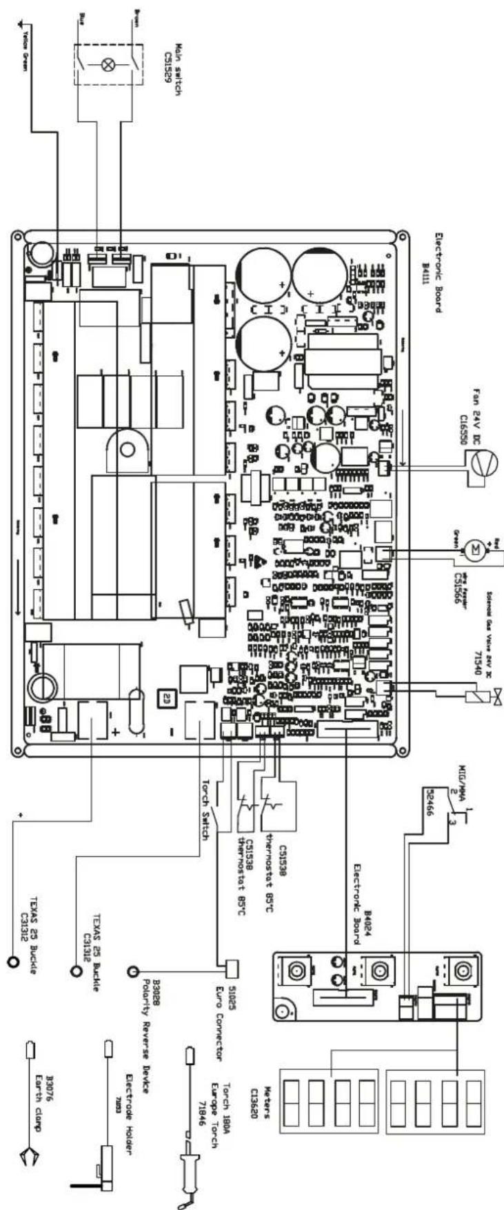
SCHÉMA ÉLECTRIQUE / CIRCUIT DIAGRAM /SCHALTPLAN/ DIAGRAMA ELECTRICO /ЭЛЕКТРИЧЕСКАЯ СХЕМА / ELEKTRISCHE SCHEMA / SCEMA ELETTRICO / SCHEMAT ELEKTRYCZNY / ELEKTRICKÁ SCHÉMA
text_image
3076 Earth clamp Texas 25 Buckle C91312 Texas 25 Buckle C91312 83028 Polarity Reverse Device B3028 Euro Converter 71025 Torch 1804 Europe Torch 71846 Meters C13620 B4024 Electronic Board Torch Switch CS1538 Thermosistat B5C CS1538 Transmosestat B5C Electronic Board P4111 ICG/HPA 2 3 71540 Sohorro Gas VWA# SW 2X CS1536 San 24V DC C16590 Fan 24V DC Main switch CIS529SPÉCIFICATIONS TECHNIQUES / TECHNICAL SPECIFICATIONS / TECHNISCHE DATEN / ESPECIFICACIONES TÉCNICAS / ТЕХНИЧЕСКИЕ СПЕЦИФИКАЦИИ / TECHNISCHE GEGEVENS / SPECIFICHE TECNICHE / DANE TECHNICZNE / TECHNICKÉ VLASTNOSTI
| Primaire / Primary / Primär / Primario / Первичка / Primaire / Primario | ||
| Tension d'alimentation / Power supply voltage / Versorgungsspannung / Tensión de red eléctrica / Напряжение питания / Voedingsspanning / Tensione di alimentazione | U1 | 230 V +/- 15% |
| Fréquence secteur / Mains frequency / Netzfrequenz / Frecuencia / Частота сети / Frequentie sector / Frequenza settore | 50 / 60 Hz | |
| Nombre de phases / Number of phases / Anzahl der Phasen / Número de fases / Количество фаз / Aantal fasen / Numero di fase | 1 | |
| Fusible disjoncteur / Fuse / Sicherung / Fusible disyuntor / Плавкий предохранитель прерывателя / Zekering hoofdschakelaar / Fusibile disgiuntore | 16 A | |
| Courant d'alimentation effectif maximal / Maximum effective supply current / Corriente de alimentación efectiva máxima / Maximale effectieve voedingsstroom / Corrente di alimentazione effettiva massima / Maksymalny efektywny prąd zasiliania | I1eff | 15.5 A |
| Courant d'alimentation maximal / Maximum supply current / Corriente de alimentación máxima / Maximale voedingsstroom / Corrente di alimentazione massima / Maksymalny prąd zasiliania | I1max | 34.5 A |
| Section du cordon secteur / Mains cable section / Sectie netsnoer / Sección del cable de alimentación / Sezione del cavo di alimentazione / Odinek przewodu zasilającego | 3 x 1.5 mm2 | |
| Puissance active maximale consommée / Maximum active power consumed / Consumo máximo de energía activa / Maximale actieve verbruikte vermogen / Potenza attiva massima consumata / Maksymalny pobór mocy czynnej | 4 976 W | |
| Consommation au ralenti / Idle consumption / Consumo en ralentizado / Stationair verbruik / Consumo al minimo / Zużycie na biegu jałowym | 84 W | |
| Rendement à l2max / Efficiency at l2max / Eficiencia a l2máx / Rendement bij l2max / Efficienza a l2max / Sprawność przy l2max | 86.5 % | |
| Facteur de puissance à l2max / Power factor at l2max / Factor de potencia a l2max / Inschakelduur bij l2max / Ciclo di potenza a l2max / Współczynnik mocy przy l2max | λ | 0.63 |
| Classe CEM / EMC class / Classe CEM / Klasse CEM / Classe CEM / Klasa EMC A | ||
| Secondaire / Secondary / Sekundär / Secundario / Вторичка / Secondair / Secondario MIG-MAG MMA | ||
| Tension à vide / No load voltage / Leerlaufspannung / Tensión al vacío / Напряжение холостого хода / Nullastspanning / Tensione a vuoto | U0(TCO) | 59 V |
| Nature du courant de soudage / Type of welding current / Tipo de corriente de soldadura / Type lasstroom / Tipo di corriente di saldatura / Rodzaj prądu spawania | DC | |
| Modes de soudage / Welding modes / Modos de soldadura / Lasmodules / Modalità di saldatura / Tryby spawania | MIG-MAG / MMA | |
| Courant de soudage minimal / Minimum welding current / Corriente mínima de soldadura / Minimale lasstroom / Corrente mínima di saldatura / Minimalny prąd spawania | 30 A 20 A | |
| Courant de sortie nominal / Rate current output / nominaler Arbeitsstrom / Corriente de salida nominal / Номинальный выходной ток / Nomiale uitgangsstroom / Corrente di uscita nominale | I2 | 30 → 180 A |
| Tension de sortie conventionnelle / Conventional voltage output / entsprechende Arbeitsspannung / Условное выходные напряжения / Tensión de salida convencional / Conventionelle uitgangsspanning / Tensione di uscita convenzionale | U2 | 15.5 → 23 V 20.8 → 26 V |
| * Facteur de marche à 40°C (10 min), Norme EN60974-1 / Duty cycle at 40°C (10 min), Standard EN60974-1.Einschaltdauer @ 40°C (10 min), EN60974-1-Norm / Ciclo de trabajo a 40°C (10 min), Norma EN60974-1/ ПВ% при 40°C (10 мин), Норма EN60974-1. / Inschakelduur bij 40°C (10 min), Norm EN60974-1, Ciclo di lavoro a 40°C (10 min), Norma EN60974-1. | Imax | 20 % 20 % |
| 60 % | 110 A 100 A | |
| 100 % | 90 A 80 A | |
| Diamètre minimal et maximal du fil d'apport / Minimum and maximum diameter of filler wire / Minimalier und maximaler Durchmesser des Schweisfülldrahtes / Diâmetro mínimo y máximo del hilo de soldadura / Минимальный и максимальный диаметр присадочной проволоки / Minimale en maximale diameter van het lasdraad / Diametro mínimo e massimo del fillo d'apporto | Acier / Steel | 0.6 → 0.8 mm |
| Inox / Stainless | 0.8 mm | |
| Aluminium | 0.8 → 1.0 mm | |
| Fil fourré /Cored wire | 0.6 → 0.9 mm | |
| Connectique de torche / Torch connector / Brenneranschluss / Conexiones de antorcha / Соединения горелки / Aansluiting toortis / Connettori della torcia | EURO | |
| Type de galet / Drive roller type / Drahtführungsrolle-Typ / Tipo de rodillo / Тип ролика / Type draadaanvoerrol / Tipo di rullo | A | |
| Vitesse de dévidage / Motor speed / Motor-Drehzahl / Velocidad de motor / Скорость двигателя / Snelheid motor / Velocità del motore | 3 → 10 m/min | |
| Puissance du moteur / Motor power / Leistung des Motors / Potencia del motor / Vermogen van de motor / Potenza del motore | 50 W | |
| Diamètre maximal de la bobine d'apport / Maximum diameter of the supply reel / Maximaler Durchmesser der Schweißfülldrahtspule / Diâmetro máximo de la bobina de alambre / Максимальный диаметр проволочной бобины / Maximale diameter van de spoel / Diâmetro massimo della bobina d'apporto | ∅ 300 mm | |
| Poids maximal de la bobine de fil d'apport / Maximum weight of the filler wire reel / Maximales Gewicht der Schweißfülldrahtspule / Peso máximo de la bobina de alambre / Максимальный вес проволочной бобины / Maximale gewicht van de spoel / Peso massimo della bobina del fillo d'apporto | 15 kg | |
| Pression maximale de gaz / Maximum gas pressure / Maximaler Gasdruck / Presión máxima del gas / Максимальное давление газа / Maxi-male gasdruk / Pressione massima del gas | Pmax | 0.5 MPa (5 bar) |
| Température de fonctionnement / Functionning temperature / Betriebstemperatur / Temperatura de funcionamiento / Рабочая температура / Gebruikstemperatuur / Temperatura di funzionamento | -10°C → +40°C | |
| Température de stockage / Storage temperature / Lagertemperatur / Temperatura de almacenaje / Температура хранения / Bewaartemperatuur / Tempe-ratura di stoccaggio | -20°C → +55°C | |
| Degré de protection / Protection level / Schutzart / Grado de protección / Степень защиты / Beschemingsklasse / Grado di protezione | IP21 | |
| Classe d'isolation minimale des enroulements / Minimum coil insulation class / Clase mínima de aislamiento del bobinado / Minimale isolatieklasse omwik-kelingen / Classe mínima di isolamento degli avvolgimenti / Minimalna klasa izolacji okablowania | B | |
| Dimensions (Lxlxh) / Dimensions (LxWxH) / Abmessungen (Lxbxt) / Dimensiones (Lxlxh) / Размеры (ДхШхВ) / Afmetingen (Lxlxh) / Dimensioni (Lxlxh) | 53 x 28 x 45 | |
| Poids / Weight / Gewicht / Bec / Peso / Gewicht / Peso | 16.5 kg | |
The duty cycles are measured according to standard EN60974-1 à 40°C and on a 10 min cycle. While under intensive use (> to duty cycle) the thermal protection can turn on, in that case, the arc switches off and the indicator switches on. Keep the machine's power supply on to enable cooling until thermal protection cancellation. The welding power source describes an external drooping characteristic. The power supply shows a flat output pattern... In some countries, UO is called TCO.