WF 20 - Welding machine GYS - Free user manual and instructions
Find the device manual for free WF 20 GYS in PDF.

| Brand | GYS |
| Model | WF 20 |
| Product Type | Separate wire feeder for semi-automatic welding (MIG/MAG) and TIG Lift |
| Welding Processes | MIG/MAG (steel, stainless steel, aluminum, gasless flux-cored wire) and TIG DC (Lift) |
| Accepted Spool Diameter | 200 mm and 300 mm |
| Wire Diameter | ∅ 0.8 to 1.6 mm (steel/stainless/alu), ∅ 0.9 to 1.6 mm (flux-cored wire) |
| Drive Rollers Supplied | Double groove steel ∅ 1.0/1.2 mm |
| Compatible Generator | MULTIWELD 400T G (ref. 083974) |
| Protection Rating | IP23 |
| Operating Temperature | -10 °C to +40 °C |
| Storage Temperature | -20 °C to +55 °C |
| Ambient Humidity | ≤ 50% at 40 °C, ≤ 90% at 20 °C |
| Maximum Altitude | 1000 m |
| Display | Voltage, current and wire speed |
| Settings | Voltage, wire speed, inductance, gas purge, wire advance |
| Trigger Modes | 2T and 4T (MIG/MAG and TIG), Valve mode (TIG) |
| Maintenance | Regular dusting, check connections, annual maintenance by qualified personnel |
| Safety | Personal protection, grounding, emergency stop, EMF precautions |
| Warranty | 2 years (parts and labor) |
| Optional Accessories | TIG torch, polarity reversal cable, specific drive rollers, beams of different lengths |
Frequently Asked Questions - WF 20 GYS
User questions about WF 20 GYS
0 question about this device. Answer the ones you know or ask your own.
Ask a new question about this device
Download the instructions for your Welding machine in PDF format for free! Find your manual WF 20 - GYS and take your electronic device back in hand. On this page are published all the documents necessary for the use of your device. WF 20 by GYS.
USER MANUAL WF 20 GYS
natural_image
Line drawing of a portable industrial machine with wheels and control panel (no text or symbols)| FR | 02-04 / 05-13 / 76-80 |
| EN | 02-04 / 14-22 / 76-80 |
| DE | 02-04 / 23-31 / 76-80 |
| ES | 02-04 / 32-40 / 76-80 |
| RU | 02-04 / 41-49 / 76-80 |
| NL | 02-04 / 50-58 / 76-80 |
| IT | 02-04 / 59-67 / 76-80 |
| PL | 02-04 / 68-75 / 76-80 |
WF 20
Dévidoir séparé
Wire feeder
Drahtvorschubkoffer
Devanadera
Подающее устройство
Draadaanvoersysteem
Trainafilo
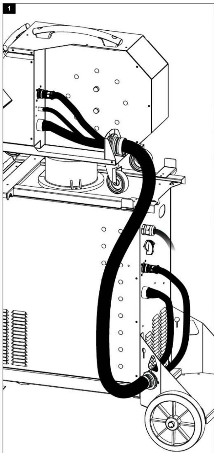
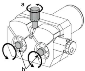
BRANCHEMENT FAISCEAU (OPTION) / CONNECTING TO A POWER SOURCE (OPTIONAL)
400T G
natural_image
Technical line drawing of a mechanical device with hoses and wheels (no text or symbols)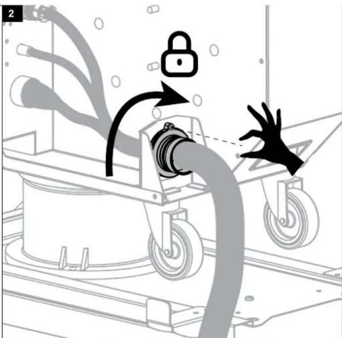
natural_image
Illustration of a mechanical device with a lock and hand interacting, no text or symbols present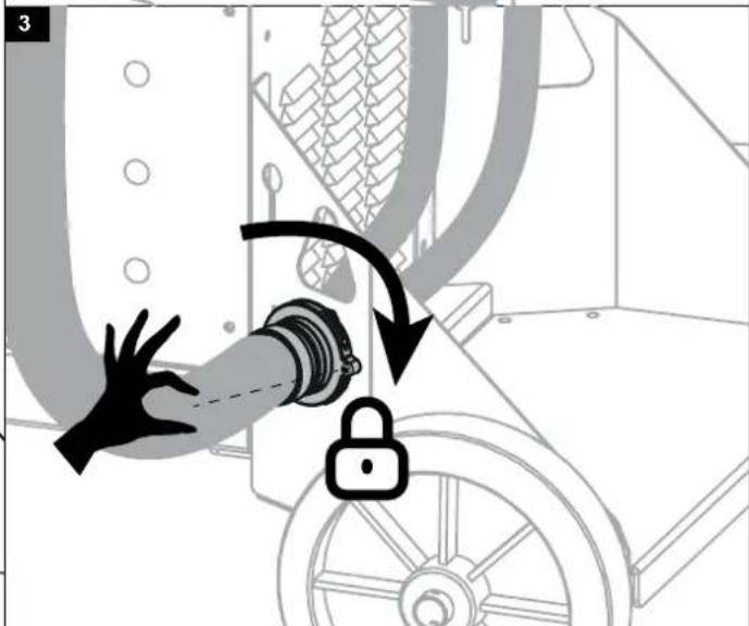
EN Lock the support using the screw.
III
AVERTISSEMENTS - RÈGLES DE SÉCURITÉ
CONSIGNE GÉNÉRALE

INSTALLATION – FONCTIONNEMENT PRODUIT
INTERFACE HOMME-MACHINE (III)
natural_image
Mechanical assembly diagram showing a rotating component with flanges and a knob (no text or symbols)ANOMALIES, CAUSES, REMÈDES
CONDITIONS DE GARANTIE
These instructions must be read and fully understood before use. Do not carry out any alterations or maintenance work that is not directly specified in this manual.
The manufacturer shall not be liable for any damage to persons or property resulting from use not in accordance with the instructions in this manual. In the event of any problems or uncertainty, please consult a person qualified to deal with the unit correctly. Read the welding machine's instruction manual before using the wire feeder.
ENVIRONMENT
This equipment should only be used for welding operations performed within the limits indicated on the information panel and/or in this manual. These safety guidelines must be observed. In the event of improper or dangerous use, the manufacturer cannot be held responsible.
The equipment must be operated and stored in a location that is free of dust, acid, flammable gases or any other corrosive substances. Operate the machine in an open, or well-ventilated area.
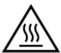
Temperature range: Use between -10 and +40°C (+14 and +104°F). Store between -20 and +55°C (-4 and 131°F). Air humidity: Lower than or equal to 50% at 40°C (104°F). Lower than or equal to 90% at 20°C (68°F). Altitude: Up to 1,000 m above sea level (3280 feet).
PROTECTING YOURSELF AND OTHERS
Arc welding can be dangerous and cause serious injury or death.
Welding exposes people to a dangerous source of heat, light radiation from the arc, electromagnetic fields (caution to those using pacemakers) and risk of electrocution, as well as noise and fumes.
To protect yourself and others, please observe the following safety instructions:

To protect yourself from burns and radiation, wear clothing that does not have turn-ups, that is insulating, dry, flame-retardant and in good condition, and that covers the whole body.

Wear protective gloves which provide electrical and thermal insulation.

Use welding protection and/or a welding helmet with a sufficient level of protection (depending on the specific use). Protect your eyes during cleaning procedures. Contact lenses are strictly prohibited. It may be necessary to section off the welding area with fireproof curtains to protect the area from arc radiation and hot spatter. Inform people in the welding area not to stare at the arc rays or molten parts and to wear appropriate clothing for protection.

Wear noise-cancelling headphones if the welding process becomes louder than the permissible limit (this is also applicable to anyone else in the welding area).
Keep hands, hair and clothing away from moving parts (the ventilation fan, for example).
Never remove the protective covers from the cooling unit while the welding power source is switched on, the manufacturer cannot be held responsible in the event of an incident.
Newly welded parts are hot and can cause burns when handled. When maintenance work is carried out on the torch or electrode holder, ensure that it is sufficiently cold by waiting at least 10 minutes before carrying out any work. The cooling unit must be switched on when using a water-cooled torch to ensure that the liquid cannot cause burns.
It is important to ensure that the work area is safe before leaving it, to help protect both people and property.
WELDING FUMES AND GAS

The fumes, gases and dusts emitted by welding are harmful to health. Sufficient ventilation must be provided and an additional air supply may be required. An air-fed mask could be a solution in situations where there is inadequate ventilation. Check the extraction system performance against the relevant safety standards.
Caution: Welding in confined spaces requires safety monitoring from a safe distance. In addition, welding certain materials containing lead, cadmium, zinc or mercury, or even beryllium, can be particularly harmful, so degrease the parts before welding them.
Cylinders should be stored in open or well-ventilated areas. They should be stored in an upright position and kept on a stand or trolley. Welding should not be carried out near grease or paint.
RISK OF FIRES AND EXPLOSIONS

Fully shield the welding area, flammable materials should be kept at least 11 metres away.
Fire-fighting equipment should be kept close to wherever the welding activities are being undertaken.
Beware of hot material, spatter or sparks being projected, even through cracks, as these can be a source of fire or explosion.
Keep people, flammable objects and pressurised containers at a safe distance.
Welding in closed containers or tubes is to be avoided. If the containers or tubes are open, they must be emptied of all flammable or explosive materials (oil, fuel, gas residues, etc.).
Grinding work must not be directed towards the source of the welding current or towards any flammable materials.
GAS CYLINDERS
Gas escaping from cylinders can cause suffocation if there is too high a concentration of it in the welding area (ensure good ventilation).
The machine must be transported in complete safety: gas cylinders must be closed and the welding power source turned off. They should be stored upright and supported to limit the risk of falling.
Close the cylinder between uses. Beware of temperature variations and exposure to the sun.
The cylinder must not come into contact with flames, arcs, torches, earth clamps or any other sources of heat or ignition.
Be sure to keep it away from electrical and welding circuits. Never weld a pressurised cylinder.
When opening the cylinder valve, keep your head away from the valve and ensure that the gas being used is suitable for the welding process.
ELECTRICAL SAFETY

The electrical network used must be earthed. Use the recommended fuse size from the rating plate.
An electric shock, whether direct or indirect, can cause serious injury or death.
Never touch live parts connected to the live current, either inside or outside the power source casing unit (torches, clamps, cables, electrodes), as these items are connected to the welding circuit.
Before opening the device, it is imperative to disconnect it from the mains and wait 2 minutes, so that all the capacitors are discharged.
Do not touch the torch or the electrode holder and the earth clamp at the same time.
If cables or torches are damaged, they should be replaced by qualified and authorised personnel. Measure the cable cross-section according to the intended application. Always use dry and in-tact clothing to insulate yourself from the welding circuit. Always wear insulated footwear, in all working environments.
INSTALLATION OF THE REEL AND LOADING OF THE WIRE

Isolate the welder from the welding voltage!
Not all the different parts involved in the welding current can be protected against direct human contact. The welder must therefore avoid the risks by following the relevant safety regulations. Even contact with low current may take the operator by surprise and cause an accident..
- Make sure any protective clothing worn is dry and in good condition (rubber sole shoes / leather welding gloves without staples or rivets).
- Avoid direct contact with uninsulated sockets or plugs
- Always place the welding torch or electrode holder on an insulated support.

Risk of burning at the welding power connection!
If the connectors are not safely locked in place, the connectors and the cables can become hot and cause burns!
- Check the welding connectors daily and lock them in place if needed by turning them to the right.

Risk of electrocution!
If the weld is performed using different processes while the torch and the electrode holder are connected to material, a no-load voltage or welding voltage is applied to the circuits.
- Always isolate the torch and electrode holder when starting work, and during any stoppages/interruptions.
ELECTRO-MAGNETIC EMISSIONS
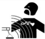
An electric current passing through any conductor produces localised electric and magnetic fields (EMF). The welding current produces an electromagnetic field around the welding circuit and the welding equipment.
Electromagnetic fields (EMFs) can interfere with some medical devices; pacemakers for example. Protective measures must be taken for people with medical implants. For example, restricted access for passers-by or an individual risk assessment for welders.
All welders should use the following guidelines to minimise exposure to the welding circuit's electromagnetic fields:
- position the welding cables together - securing them with a clamp if possible;
- position yourself (head and body) as far away from the welding circuit as possible;
- never wrap the welding cables around your body;
- do not position yourself in between the welding cables. Keep both welding cables on the same side of the body;
- connect the return cable to the workpiece, as close as possible to the welding area;
- do not work next to, sit on, or lean against the source of the welding current;
- do not weld while the current source or wire feeder is being carried.

Pacemaker users should consult a doctor before using this equipment.
Exposure to electromagnetic fields during welding may have other health effects that are not yet known.
TRANSPORT AND TRANSIT OF THE WIRE FEEDER

The wire feeder is equipped with a top handle for carrying by hand. Be careful not to underestimate the weight of the unit. The handle cannot be used to hang or attach the machine on something else.
Never lift the machine while there is a gas bottle on the support shelf. Their transportation requirements are different.
Do not carry the unit over people or objects.
The removal of the wire reel from the machine is recommended before undertaking any lifting operation.
SETTING UP THE EQUIPMENT
- Put the wire feeder on a floor with a maximum incline of 10^ .
- The product should be protected from driving rain and not be exposed to direct sunlight.
- The unit has an IP23 protection rating which means:
- the dangerous parts of the machine are protected against entry by objects greater than 12.5 mm and,
- protected against rain directed at a 60% angle from vertical.
The equipment can be used outside in accordance with the IP23 protection certification.

The manufacturer assumes no responsibility for damage to persons or objects caused by improper and dangerous use of this equipment.
Power, extension and welding cables must be completely uncoiled in order to avoid overheating.
MAINTENANCE / RECOMMENDATIONS


- Maintenance should only be carried out by a qualified person. Annual maintenance is recommended.
-
Ensure the wire feeder is disconnected from the welding machine, and wait for two minutes before carrying out maintenance work.
-
Regularly remove the cover and blow out any dust. Take this opportunity to have the electrical connections checked by a qualified person, using an insulated tool.
- Regularly check the condition of the connection cable between the wire feeder and the machine. If found damaged, the interconnection cable must be replaced.

Warning! If handling equipment other than that recommended by the manufacturer is used during welding, provide insulation between the wire feeder casing and the handling equipment.
- The wire feeder must only be used with all hatches closed.
INSTALLATION - USING THE PRODUCT
Only experienced personnel, authorised by the manufacturer, may carry out the set-up of the machine. During set-up, ensure that the power source is unplugged from the mains. It is recommended to use the welding cables supplied with the unit in order to obtain the best possible product performance.
DESCRIPTION
This product is a separate wire feeder for semi-automatic welding (MIG or MAG) and tungsten arc welding (TIG Lift). It accepts 200 and 300 mm diameter wire spools.
DESCRIPTION OF THE UNIT (II)
1- Reel support ∅ 200/300 mm 9- Power relay connector
2- Wire-feed motor 10- Gas inlet
3- Interface 11- Interconnection cable connector
4- Euro connector (torch) 12- Transport handles
5- Cache pour sortie liquide du refroidissement (Bleu)
6- Cache pour entrée liquide du refroidissement (Rouge)
7- Torch support
8- Interconnection support
13- Turret (pivot)
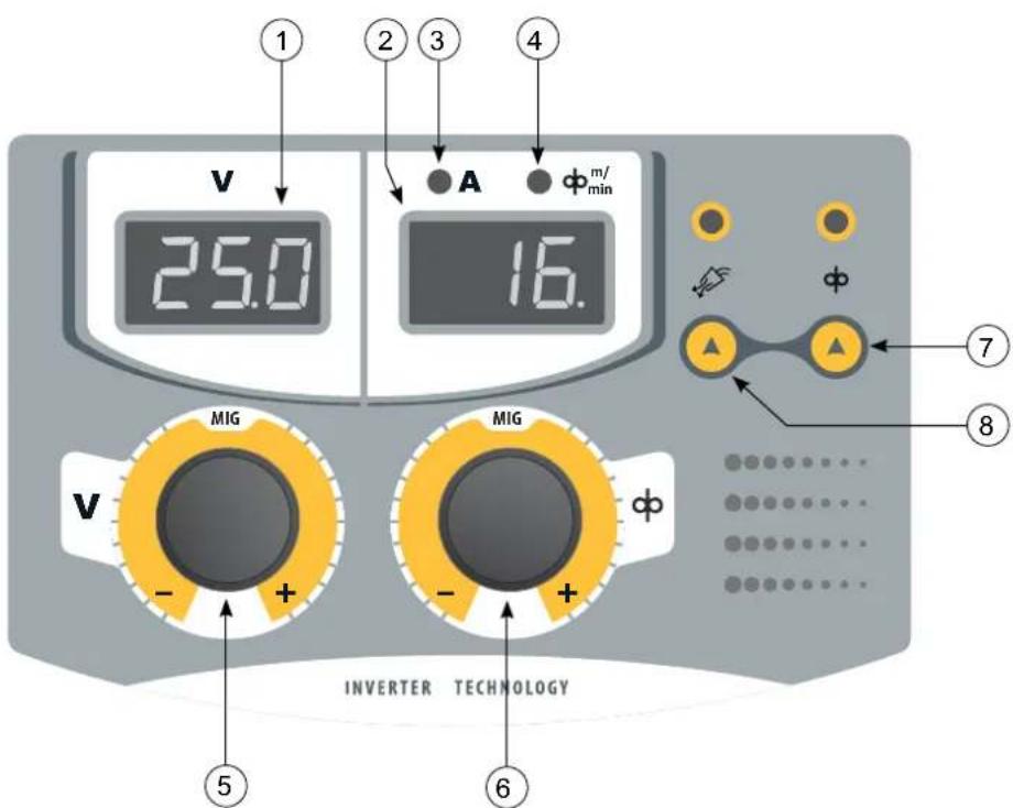
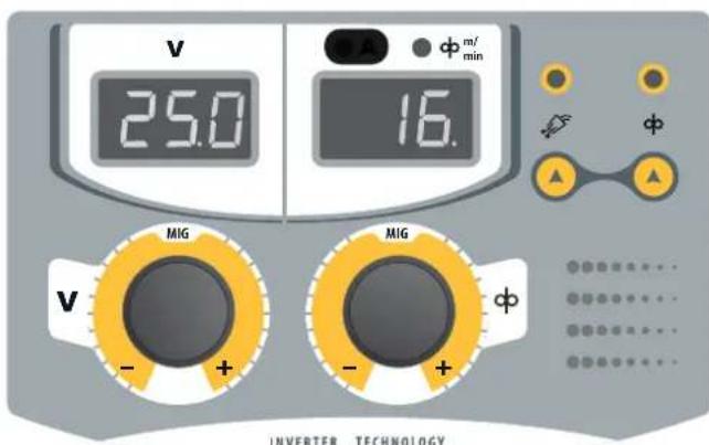
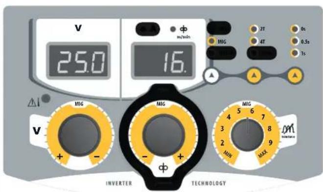
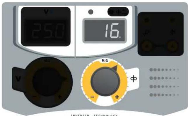
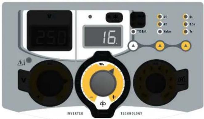
HUMAN-MACHINE INTERFACE (III)
1- Voltage display 5- Voltage adjustment
2- Current and wire speed display
3- Current indicator
4- Wire speed indicator
6- Adjusting the wire speed
7- Wire inching button
8- Gas purge button
POWER - START-UP
This unit is designed to work exclusively with the MULTIWELD 400T G power source (available separately, ref; 083974):
The connection between these two parts is made through a dedicated interconnection cable, available separately:
| Type of torch cooling | Length | Cross-section | Reference |
| Air | 5m | 70mm^2 | 083998 |
| 10m | 70mm^2 | 084001 | |
| 15 m | 95mm^2 | 084018 | |
| 20 m | 95mm^2 | 084025 |
ATTACHING THE INTERCONNECTION CABLES

Make sure the main welding power source switched off when connecting or disconnecting the wire feeder. Ensure the machine is unplugged from the mains, and then wait 2 minutes.
For connecting the interconnection cable between the power source and the wire feeder, see page 3.
SETTING UP THE REEL
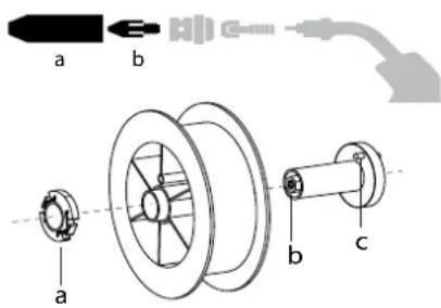
- Remove the nozzle (a) and contact tube (b) from your MIG/MAG torch.
- Open the wire feeder cover.
- Position the reel on its holder.
- Take into consideration the drive pin (c) on the spool support. To fit a 200 mm reel, tighten the plastic reel holder (a) to the maximum.
- Adjust the brake knob (b) to prevent the wire being tangled by the inertia of the spool when the weld is stopped. As a general rule, do not overtighten, as this will cause the motor to overheat.
LOADING THE FILLER WIRE
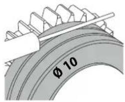
To change the rollers, do the following:
- Loosen the knob (a) as far as it will go and lower it.
- Unlock the rollers by removing the retaining screws (b)
- Fit the appropriate drive rollers for your application and retighten the retaining screws.
The rollers supplied are double groove rollers: - steel ∅ 1.0/1.2
natural_image
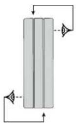
Pure diagram of a vertical cylindrical structure with directional arrows indicating flow or movement (no text or symbols)- Check the inscription on the roller to ensure that the rollers are suitable for the wire diameter and the wire material (for ∅ 1.0 wire, use the ∅ 1.0 groove).
- Use V-grooved rollers for steel and other hard wires.
- Use U-grooved rollers for aluminium and other soft, alloyed wires.

visible marking on the roller (example: ∅10 = ∅ 1.0)

: groove to be used
natural_image
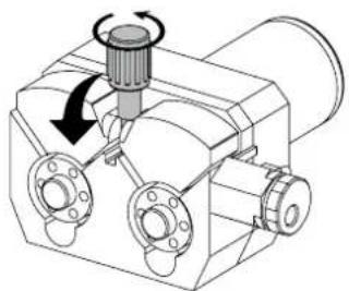
Mechanical assembly diagram showing a rotating component with flanges and a central knob (no text or symbols)To install the wire, follow the steps below:
- Loosen the knob as far as it will go and lower it.
- Insert the wire, then close the winding motor and tighten the knob as indicated.
- Activate the motor on the trigger on the torch or on the manual wire inching button (III-7).

Notes:
- A liner that is too narrow can lead to feed issues and cause the motor to overheat.
- The torch connection must also be properly tightened to prevent it from overheating.
- Check that neither the wire nor the spool touches the mechanics of the unit, otherwise there is a risk of short-circuit.
RISK OF INJURY FROM MOVING COMPONENTS
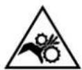
Wire feeders have moving parts that can catch hands, hair, clothing or tools, and cause injury.
- Do not touch rotating, moving or driving parts of the machine.
- Ensure that the housing doors or protective covers remain closed during operation.
- Do not wear gloves when threading the filler wire or changing the wire spool.
SEMI-AUTOMATIC STEEL/STAINLESS STEEL WELDING (MAG MODE)
This machine can weld steel and stainless steel wire from ∅ 0.8 to 1.6 mm (I-A). The unit is supplied with ∅ 1.0/1.2 rollers for steel or stainless steel as standard. The contact tip, the grooved roller, and the torch liner are designed for this application.
For use on steel, a specific welding gas (Ar+CO2) is required. The amount of CO2 may vary depending on the type of gas used. For stainless steel, use a 2% CO2 mixture. When welding with pure CO2, it is necessary to connect a gas pre-heater to the gas cylinder. It is also possible to use a standard preheating module (36V) which can be connected to the 36V power socket located in the power source (available separately), located behind the side door. Please note that this 36V DC power supply is also compatible with 36V AC preheaters. If you have specific gas requirements, please contact your gas distributor. The gas flow rate for steel is between 8 and 15 litres per minute depending on the environment. To check the gas flow on the manometer without unspooling the filler wire, press and hold the button (III-7). This check should be done periodically to ensure the best possible welding performance.
SEMI-AUTOMATIC ALUMINIUM WELDING (MIG MODE)
The unit can weld aluminium wire from ∅ 0.8 to 1.6mm (I-B).
For use with aluminium, pure argon gas (Ar) is required. When it comes to choosing your gas, ask a gas distributor for advice. The gas flow rate for aluminium is between 15 and 20 l/min depending on the surrounding environment and the welder's experience.
The differences between steel and aluminium applications are as follows:
- Use specific rollers for aluminium welding.
- Apply minimum pressure to the rollers on the wire feed motor to avoid compressing the wire.
- Only use the capillary tube (for guiding the wire between the feed rollers and the EURO connector) for steel/stainless steel welding (I-B)
- Use a dedicated aluminium torch. This aluminium torch has a teflon liner to reduce friction. DO NOT cut away the coating at the tip of the connector! This coating is used to guide the wire from the rollers.
- Contact tips: use a SPECIAL aluminium contact tip that matches the wire diameter.
GASLESS SEMI-AUTOMATIC WELDING WITH FLUX-CORED WIRE
The equipment can weld gasless flux-cored wire from ∅ 0.9 to 1.6 mm. The original rollers must be replaced by specific gasless wire rollers (available as an optional extra). Welding flux-cored wire with a standard nozzle can lead to overheating and damage to the torch. Remove the original nozzle from your MIG-MAG torch. Gasless MIG/MAG welding generally requires negative polarity. In this situation, it is necessary to use an optional polarity reversal cable. See the power source manual for connection instructions.
RECOMMENDED COMBINATIONS
| (mm) | Current (A) ∅ Wire (mm) ∅ Nozzle (mm) Flow (L/min) | |||
| M/G | 0.8-2 20-100 0 | 8 12 10-12 | ||
| 2-4 100-200 1 | 0 12-15 12-15 | |||
| 4-8 200-300 1 | 0/1.2 15-16 15-18 | |||
| 8-15 300-500 1 | 2/1.6 16 18-25 | |||
| MAG | 0.6-1.5 15-80 0 | 6 12 | 8-10 | |
| 1.5-3 80-150 0 | 8 12-15 10-12 | |||
| 3-8 150-300 1 | 0/1.2 15-16 12-15 | |||
| 8-20 300-500 1 | 2/1.6 16 15-18 | |||
MIG / MAG (GMAW/FCAW) WELDING MODE
INSTALLATION AND GUIDANCE
See power source manual.
SELECTING THE MODE AND SETTINGS
On the power source interface:
1- Press the left-hand button to select MIG welding mode.
2- Press the central button to select the trigger action: 2T or 4T.
In 2T mode, pressing the trigger on the welding torch activates the flow of shielding gas and ignites the arc. The user holds the trigger down during welding, and releases it to stop the weld.
In 4T mode, pressing the trigger on the welding torch activates the flow of shielding gas and ignites the arc. After releasing the trigger, the welding cycle continues. To stop welding, press and release the trigger again.
3- Press the right-hand button to select the duration of the gas shield (0, 0.5, or 1 second) after the arc is deactivated. This protects the workpiece against oxidation.
Wire feeder interface
The blacked-out areas are not available in this mode.
Power source interface
The blacked-out areas are not available in this mode.
- Set the welding voltage (available on the wire feeder or power source):
Adjust the welding voltage using the knob (V) to best suit the application. The voltage setting is indicated on the left-hand display.
- Set the wire speed (available on the wire feeder or power source):
Adjust the wire speed using the (∞) knob to best suit the application. The wire speed setting is indicated on the right-hand display.
- Adjust the inductance (available on the power source):
Adjust the inductance level using the (J) knob on the power source, with relative value ranging from MIN to MAX. The lower the level of inductance, the harder and more directional the arc will be, and the higher the level of inductance, the softer the arc will be, with reduced spatter.
Select the output voltage and set the wire speed according to the recommendations on the power source, depending on the thickness of the workpiece you are welding.
GAS PURGE (available on the wire feeder)
The gas purge button ( ) is used to empty the torch of all the gas it contains without unwinding the welding wire, and is also used to check the gas flow on the pressure gauge.
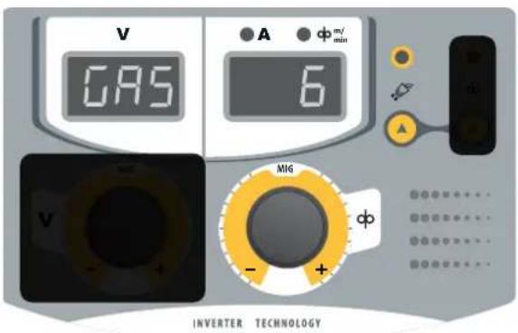
Press the (√) button for a moment to start the gas purge. The right-hand display will scroll through the sequence (7-6-5-...-1). The factory default setting is 7 seconds. This countdown lets you keep your hands free to adjust the gas flow on the pressure gauge.
To change the gas purge time, press the ( ) button momentarily and turn the right-hand knob. The time can be set between 3 and 60 seconds. The sequence starts after you have made your choice, or press the ( ) button again momentarily to confirm and save your setting.
WIRE INCHING (available on wire feeder)
The wire inching button (∞) is used to feed the filler wire without activating the gas or the welding system. It is intended for unwinding the wire through the torch sheath when fitting a new wire spool. Hold the button down to start unwinding the wire, release the button to stop.
TIG (GTAW) WELDING MODE
INSTALLATION AND GUIDANCE
- DC TIG welding requires a protective gas shield (Argon).
- Connect the earth clamp to the positive (+) plug connector. Connect the optional TIG torch (ref. 087606) into the EURO connector on the wire feeder (II-4) and the inversion cable into the negative connector (-). See the power source manual for more details.
- Ensure that the torch is properly fitted and that the consumables (collets and collet bodies, diffusers and nozzles) are not worn out.
- The choice of electrode will depend on the current of the DC TIG process.
ELECTRODE SHARPENING
For optimum performance, we recommend using an electrode sharpened as follows:
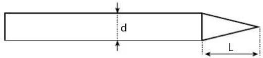
L = 3 x d for low current.
L = d for high current
RECOMMENDED COMBINATIONS
| (mm) | Current (A) ∅ Electrode (mm) ∅ Nozzle (mm) Argon flow rate (L/min) | |||
| 0.3 - 3 3 - 75 1 6.5 6 - 7 | ||||
| 2.4 - 6 | 60 - 150 | 1.6 | 8 | 6 - 7 |
| 4 - 8 | 100 - 200 | 2 9.5 7 - 8 | ||
| 6.8 - 8.8 | 170 - 250 | 2.4 | 11 | 8 - 9 |
| 9 - 12 | 225 - 300 | 3.2 | 12.5 | 9 - 10 |
SELECTING THE MODE AND SETTINGS
On the power source interface:
1- Press the left-hand button to select the TIG Lift welding mode.
2- Press the central button to select the trigger action: 2T, 4T or Valve (triggerless torch).
In 2T mode, position the tip of the tungsten electrode on the workpiece and press the trigger on the torch to activate the flow of gas. Then lift the tungsten electrode to start the arc. The user holds the trigger down during welding, and releases it to stop the weld.
In 4T mode, position the tip of the tungsten electrode on the workpiece and press the trigger on the torch to trigger the flow of gas. Then lift the tungsten electrode to strike the arc at 20 A. After releasing the trigger, the welding cycle continues. Pull the trigger on the torch a second time and the cycle will switch to 'DownSlope' (60% welding current). To end the weld, release the torch trigger a second time.
In 'Valve' mode, set the gas flow rate on the gas bottle pressure regulator, then open the torch valve. Position the tip of the tungsten electrode on the workpiece to start the arc. To stop welding, quickly lift the torch, or raise the arc once (up-down). Close the valve on the torch to stop the gas once the electrode has cooled down.
3- Press the right-hand button to select the duration that the gas shield will continue to run (0, 0.5 or 1 second) after the arc is extinguished (not available with valve torch). This protects the workpiece against oxidation.
Wire feeder interface Power source interface
The blacked-out areas are not available in this mode. The blacked-out areas are not available in this mode.
Adjusting the welding current:
Adjust the welding current using the knob ( ) to best suit the application. The welding current setpoint is shown on the right-hand display.
ROLLERS (B) OPTIONAL
| Diameter | Reference (x2)Steel Aluminum Flux-cored w | |
| 0.6/0.8 042353 - 0.9/1.2 042407 | ||
| 0.8/1.0 042360 042377 1.2/1.6 | ||
| 1.0/1.2 046849 040915 | ||
| 1.2/1.6 042384 042391 | ||
089280
| Diameter | Reference (x2) |
DEFECTS, CAUSES, AND SOLUTIONS
| SYMPTOMS | POSSIBLE CAUSES | SOLUTIONS |
| The wire feed speed is not constant. | The opening is obstructed by spatter | Clean the contact tube or replace it with an anti-adhesion product. |
| The wire is slipping on the rollers. | Re-apply anti-adhesion product. | |
| One of the rollers is spinning. | Ensure that the roller screw is tight. | |
| The torch cable is twisted. | The torch cable should be as straight as possible. | |
| The feed motor is not working. | Spool brake or roller over-tightened. | Loosen the brake and rollers. |
| The wire is not unwinding properly. | Dirty or damaged wire guide shaft. | Clean or replace. |
| Roller shaft pin is missing | Replace the pin in its recess | |
| Spool brake too tight. | Loosen the brake. | |
| No current or incorrect welding current. | The mains plug is incorrectly connected. | Check that the plug is connected correctly and that there is power to the socket. |
| Poor earth connection. | Check the earth cable (connection and condition of the clamp). | |
| No power. | Check the torch trigger. | |
| The wire gets blocked after the rollers | Wire guide sleeve squashed. | Check the wire-guide sleeve and body of the torch. |
| Wire blockage in the torch. | Replace or clean. | |
| No capillary tube. | Check that the capillary tube is present. | |
| Wire speed too high. | Reduce the wire feed speed | |
| The weld bead is porous. | The gas flow is insufficient. | Adjustment range from 15 to 20 L / min.Clean the base metal. |
| Gas cylinder empty. Replace it. | ||
| Unsatisfactory gas quality. Replace it. | ||
| Air or wind circulation or influence. Prevent draughts, protect the welding area. | ||
| Gas nozzle excessively contaminated. Clean or replace the gas nozzle. | ||
| Poor quality wire. Use a wire suitable for MIG/MAG welding. | ||
| Condition of the welding surface is not good enough (rust, etc.) | Clean the workpiece before welding. | |
| The gas is not connected. | Check that the gas is connected to the inlet on the power source. | |
| Excessive sparking. | Arc voltage is too low or too high. See welding settings. | |
| Poor earth connection. | Position the earth clamp as close as possible to the area you intend to weld. | |
| Insufficient gas protection. Adjust the gas flow. | ||
| No gas coming from the torch. Poor gas connection. | Check the gas inlet connections | |
| Check that the solenoid valve is working | ||
WARRANTY CONDITIONS
The warranty covers any defects or manufacturing faults for two years from the date of purchase (parts and labour).
The warranty does not cover:
- Any other damage caused during transport.
• The general wear and tear of parts (i.e.: cables, clamps, etc.). - Incidents caused by misuse (incorrect power supply, dropping or dismantling).
- Environment-related faults (such as pollution, rust and dust).
In the event of a breakdown, please return the item to your distributor, along with:
- dated proof of purchase (receipt, invoice, etc.),
a note explaining the malfunction.
natural_image
Mechanical assembly diagram showing a rotating component with flanges and a knob (no text or symbols)natural_image
Pure diagram of a vertical cylindrical structure with directional arrows indicating flow or movement (no text or symbols)natural_image
Mechanical assembly diagram showing a rotating component with flanges and a central knob (no text or symbols)natural_image
Mechanical assembly diagram showing a rotating component with flanges and a knob (no text or symbols)WAARSCHUWINGEN - VEILIGHEIDSINSTRUCTIES
ALGEMENE INSTRUCTIES
INSTALLATIE - WERKING VAN HET APPARAAT
HUMAN MACHINE INTERFACE (III)
natural_image
Mechanical assembly diagram showing a rotating component with flanges and a knob (no text or symbols)natural_image
Mechanical assembly diagram showing a rotating component with flanges and a knob (no text or symbols)RYZYKO POŻARU I WYBUCHU

natural_image
Pure diagram of a vertical cylindrical structure with directional arrows indicating flow or movement (no text or symbols)natural_image
Mechanical assembly diagram showing a rotating component with flanges and a knob (no text or symbols)WYBÓR TRYBU I USTAWIENIA
WYBÓR TRYBU I USTAWIENIA
| 1 Charnière / Hinge C31413 | ||
| 2 Poignée taille M / Handle size M 56048 | ||
| 3 Verrou / Lock 71003 | ||
| 4 Fenêtre dévidoir / Wirefeeder window 56238 | ||
| 5 Poignée taille S / Handle size S 56047 | ||
| 6 Support bobine / Reel support 71503 | ||
| 7 Circuit de contrôle / Panel board B4186 | ||
| 8 Molette / Knob C13873 | ||
| 9 Motodévidoir / Wirefeeder C51568 | ||
| 10 Carte d'adaptation d'interconnexion / Interconnection adaptation board | B4185 | |
| 11 Circuit dévidoir WF20 / Wirefeeder circuit WF20 | B4182 | |
| 12 Electrovanne / Solenoid valve | 71542 | |
| 13 Embase Texas / Texas connector | 51481 | |
| 14 Tourelle (en 2 parties) / Turret (in 2 parts) | 72006 | |
| 15 Roues / Wheels | 71864 |
CIRCUIT DIAGRAM / SCHALTPLAN / DIAGRAMA ELECTRICO / ЭЛЕКТРИЧЕСКАЯ СХЕМА / ELEKTRISCHE SCHEMA / SCEMA ELETTRICO
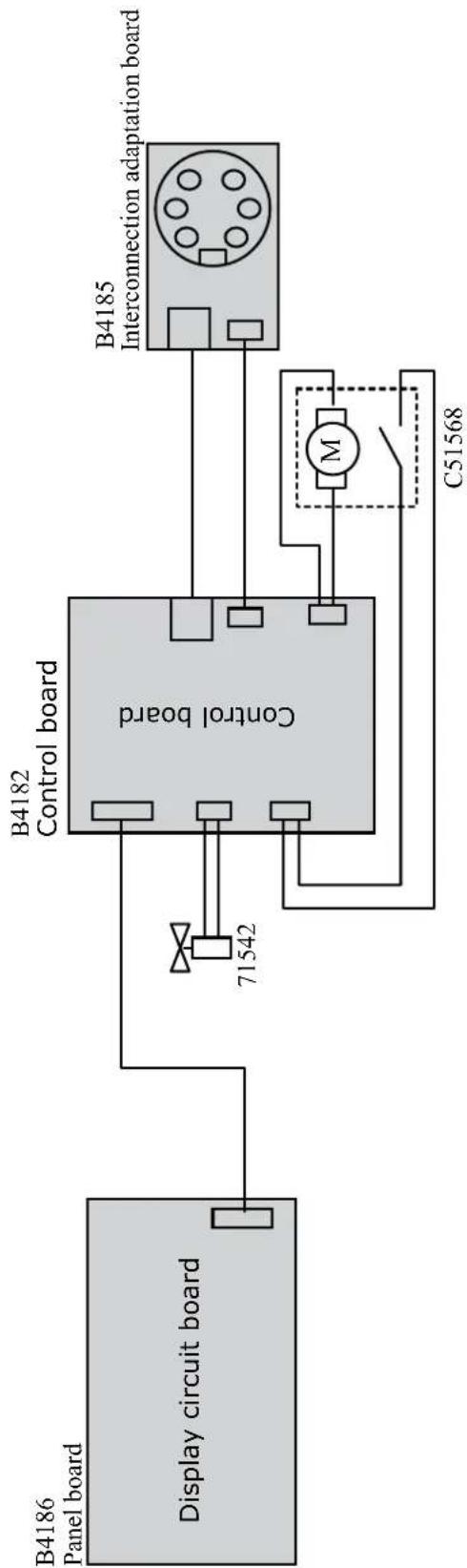
flowchart
graph LR
    A["Display circuit board"] --> B["Control board"]
    B --> C["B4182 Control board"]
    C --> D["B4185 Interconnection adaptation board"]
    B --> E["71542"]
    E --> F["C51568"]
    F --> G["M"]
TECHNICAL SPECIFICATIONS / TECHNISCHE DATEN / ESPECIFICACIONES TÉCNICAS / ТЕХНИЧЕСКИЕ СПЕЦИФИКАЦИИ / TECHNISCHE GEGEVENS / SPECIFICHE TECNICHE
| Tension d'alimentation (DC) / Power supply voltage (DC) / Versorgungsspannung (DC) / Tensión de red eléctrica (DC) / Напряжениепитания (DC) / Voedingsspanning (DC) / Tensione di alimentazione (DC) | U1 | 24 V DC | |
| * Facteur de marche à 40°C (10 min), Norme EN60974-1 / Duty cycle at 40°C (10 min), Standard EN60974-1. Einschaltdauer @ 40°C (10 min), EN60974-1-Norm / Ciclo de trabajo a 40°C (10 min), Norma EN60974-1/ ПВ% при 40°C (10 мин), Норма EN60974-1. / Inschakelduur bij 40°C (10 min), Norm EN60974-1, Ciclo di lavoro a 40°C (10 min), Norma EN60974-1. | 60 % | 500 A | |
| 100 % | 400 A | ||
| Diamètre minimal et maximal du fil d'apport / Minimum and maximum diameter of filler wire / Minimaler und maxi-maler Durchmesser des Schweißfülldrahtes / Diámetro mínimo y máximo del hilo de soldadura / Минимальный и максимальный диаметр присадочной проволоки / Minimale en maximale diameter van het lasdraad / Diametro mínimo e massimo del filo d'apporto | Acier / Steel | 0.6 → 1.6 mm | |
| Inox / Stainless | 0.6 → 1.6 mm | ||
| Aluminium | 0.8 → 1.6 mm | ||
| Fil fourré / Wire cored | 0.9 → 1.6 mm | ||
| Connectique de torche / Torch connector / Brenneranschluss / Conexiones de antorcha / Соединения горелки / Aansluiting toorts / Connettori della torcia | Euro | ||
| Type de galet / Drive roller type / Drahtführungsrolle-Typ / Tipo de rodillo / Тип ролика / Type draadaanvoerrol / Tipo di rullo | B | ||
| Vitesse de dévidage / Motor speed / Motor-Drehzahl / Velocidad de motor / Скорость двигателя / Snelheid motor / Velocità del motore | 1.5 → 21 m/min | ||
| Puissance du moteur / Motor power / Leistung des Motors / Potencia del motor / Vermogen van de motor / Potenza del motore | 50 W | ||
| Diamètre maximal de la bobine d'apport / Maximum diameter of the supply reel / Maximaler Durchmesser der Schweißfülldrahtspule / Diámetro máximo de la bobina de alambre / Максимальный диаметр проволочной бобины / Maximale diameter van de spoel / Diametro massimo della bobina d'apporto | ∅ 300 mm | ||
| Poids maximal de la bobine de fil d'apport / Maximum weight of the filler wire reel / Maximales Gewicht der Schweißfülldrahtspule / Peso máximo de la bobina de alambre / Максимальный вес проволочной бобины / Maximale gewicht van de spoel / Peso massimo della bobina del filo d'apporto | 18 kg | ||
| Pression maximale de gaz / Maximum gas pressure / Maximaler Gasdruck / Presión máxima del gas / Максимальное давление газа / Maximale gasdruk / Pressione massima del gas | Pmax | 0.5 MPa (5 bar) | |
| Température de fonctionnement / Functionning temperature / Betriebstemperatur / Temperatura de funcionamiento / Рабочая температура / Gebruikstemperatuur / Temperatura di funzionamento | -10°C → +40°C | ||
| Température de stockage / Storage temperature / Lagertemperatur / Temperatura de almacenaje / Температура хранения / Bewaartemperatuur / Temperatura di stoccaggio | -20°C → +55°C | ||
| Degré de protection / Protection level / Schutzart / Grado de protección / Степень защиты / Beschemingsklasse / Grado di protezione | IP23 | ||
| Dimensions (Lxlxh) / Dimensions (LxWxH) / Abmessungen (Lxbxt) / Dimensiones (Lxlxh) / Размеры (ДхШхВ) / Afmetingen (Lxlxh) / Dimensioni (Lxlxh) | 58 x 26 x 48 cm | ||
| Poids / Weight / Gewicht / Bec / Peso / Gewicht / Peso 15 kg | |||
*Les facteurs de marche sont réalisés selon la norme EN80974-1 à 40°C et sur un cycle de 10 min. Lors d'utilisation intensive (supérieur au facteur de marche) la protection thermique peut s'enciencher, dans ce cas, l'arc sé étent et le témoin) s'allume. Laissez l'appareil alimenté pour permettre son réfroidissement jusqu'à annulation de la protection. Pour ne pas endommager le dévidor, le facteur de marche de la source de courant de soudage doit toujours être inférieur a celui indiqué sur le dévidor.
*The duty cycles are measured according to standard EN80974-1 à 40°C and on a 10 min cycle. While under intensive use (> to duty cycle) the thermal protection can turn on, in that case, the arc switches off and the indicator switches on. Keep the machine's power supply on to enable cooling until thermal protection cancellation. To prevent damage to the wire feeder, the duty cycle of the welding current source should always be lower than that indicated on the wire feeder.
* Einschaltdauer gemäß EN60974-1 (10 Minuten - 40°C). Bei sehr intensivem Gebrauch (>Einschaltdauer); kann der Thermoschutz ausgelöst werden. In diesem Fall wird der Lichtbogen abgeschaltet und die entsprechende Warnung > erscheint auf der Anzeige. Das Gerät zum Abkühlen nicht ausschalten und laufen lassen bis das Gerät wieder bereit ist. Um die Drahtvorschübeinheit nicht zu beschädigen, muss die Einschaltdauer der Schweißstromquelle immer kleiner sein als die auf der Drahtvorschübeinheit angegebene Einschaltdauer.
Los ciclos de trabajo están realizados en acuerdo con la norma EN60974-1 a 40°C y sobre un ciclo de diez minutos. Durante un uso intensivo (superior al ciclo de trabajo), se puede activar la protección térmica. En este caso, el arcó se apaga y el indicador ¡se encende. Deje el aparato conectado para permitir que se entfite hasta que se anule la protección. Para evitar danos en el devanador, el ciclo de trabajo de la fuente de corriente de soldacura debe ser siempre inferior al indicado en el devanador.