Titan 231 DC FV - Welding machine GYS - Free user manual and instructions
Find the device manual for free Titan 231 DC FV GYS in PDF.
Questions des utilisateurs sur Titan 231 DC FV GYS
0 question sur cet appareil. Repondez a celles que vous connaissez ou posez la votre.
Poser une nouvelle question sur cet appareil
Download the instructions for your Welding machine in PDF format for free! Find your manual Titan 231 DC FV - GYS and take your electronic device back in hand. On this page are published all the documents necessary for the use of your device. Titan 231 DC FV by GYS.
USER MANUAL Titan 231 DC FV GYS
INSTALLATION – FONCTIONNEMENT PRODUIT
0.00 - 60 sec. X X -
0.0 - 60 sec. X X -FR
DB torch L torch DB + P torch
Translation of the original instructions
WARNINGS - SAFETY INSTRUCTIONS
GENERAL INSTRUCTIONS These instructions must be read and fully understood before use. Do not carry out any alterations or maintenance work that is not directly specied in this manual. The manufacturer shall not be liable for any damage to persons or property resulting from use not in accordance with the instructions in this manual. In case of problems or queries, please consult a qualied tradesperson to correctly install the product. ENVIRONMENT This equipment should only be used for welding operations performed within the limits indicated on the information panel and/or in this manual. These safety guidelines must be observed. The manufacturer cannot be held responsible in the event of improper or dangerous use. The machine must be set up somewhere free from dust, acid, ammable gases or any other corrosive substances. This also applies to the machine’s storage. Operate the machine in an open, or well-ventilated area. Temperature range: Use between -10 and +40°C (+14 and +104°F). Store between -20 and +55°C (-4 and 131°F). Air humidity: Lower than or equal to 50% at 40°C (104°F). Lower than or equal to 90% at 20°C (68°F). Altitude: Up to 1,000 m above sea level (3280 feet).
PROTECTING YOURSELF AND OTHERS
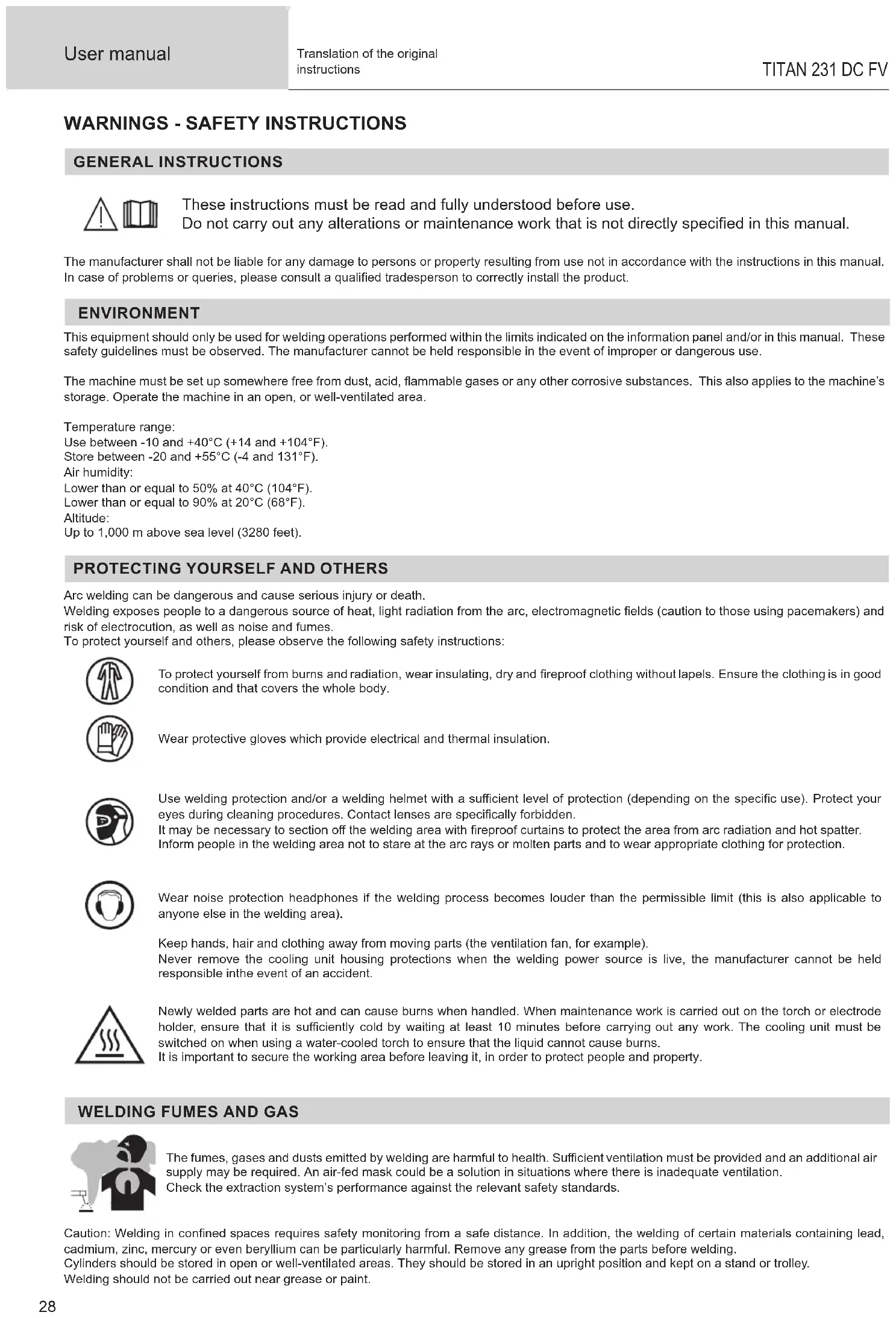
Arc welding can be dangerous and cause serious injury or death. Welding exposes people to a dangerous source of heat, light radiation from the arc, electromagnetic elds (caution to those using pacemakers) and risk of electrocution, as well as noise and fumes. To protect yourself and others, please observe the following safety instructions: To protect yourself from burns and radiation, wear insulating, dry and reproof clothing without lapels. Ensure the clothing is in good condition and that covers the whole body. Wear protective gloves which provide electrical and thermal insulation. Use welding protection and/or a welding helmet with a sucient level of protection (depending on the specic use). Protect your eyes during cleaning procedures. Contact lenses are specically forbidden. It may be necessary to section o the welding area with reproof curtains to protect the area from arc radiation and hot spatter. Inform people in the welding area not to stare at the arc rays or molten parts and to wear appropriate clothing for protection. Wear noise protection headphones if the welding process becomes louder than the permissible limit (this is also applicable to anyone else in the welding area). Keep hands, hair and clothing away from moving parts (the ventilation fan, for example). Never remove the cooling unit housing protections when the welding power source is live, the manufacturer cannot be held responsible inthe event of an accident. Newly welded parts are hot and can cause burns when handled. When maintenance work is carried out on the torch or electrode holder, ensure that it is suciently cold by waiting at least 10 minutes before carrying out any work. The cooling unit must be switched on when using a water-cooled torch to ensure that the liquid cannot cause burns. It is important to secure the working area before leaving it, in order to protect people and property.
WELDING FUMES AND GAS
The fumes, gases and dusts emitted by welding are harmful to health. Sucient ventilation must be provided and an additional air supply may be required. An air-fed mask could be a solution in situations where there is inadequate ventilation. Check the extraction system’s performance against the relevant safety standards. Caution: Welding in conned spaces requires safety monitoring from a safe distance. In addition, the welding of certain materials containing lead, cadmium, zinc, mercury or even beryllium can be particularly harmful. Remove any grease from the parts before welding. Cylinders should be stored in open or well-ventilated areas. They should be stored in an upright position and kept on a stand or trolley. Welding should not be carried out near grease or paint.EN
Translation of the original instructions
RISK OF FIRES AND EXPLOSIONS
Fully shield the welding area, ammable materials should be kept at least 11 metres away. Fire ghting equipment should be kept close to wherever the welding activities are being undertaken. Beware of spatter or spark projection, as they are a potential source of re or explosion, even through cracks. Keep people, ammable objects and pressurised containers at a safe distance. Welding in closed containers or tubes is to be avoided. If the containers or tubes are open, they must be emptied of all ammable or explosive materials (oil, fuel, gas residues, etc.). Grinding work must not be directed towards the source of the welding current or towards any ammable materials. GAS CYLINDERS Gas escaping from cylinders can cause suocation if there is too high a concentration of it in the welding area (ensure good ventilation). The machine must be transported in complete safety: gas cylinders must be closed and the welding power source turned o. They should be stored upright and supported to limit the risk of falling. Close the cylinder between uses. Beware of temperature variations and exposure to the sun. The cylinder must not come into contact with ames, arcs, torches, earth clamps or any other sources of heat or ignition. Be sure to keep it away from electrical and welding circuits. Never weld a pressurised cylinder. When opening the cylinder valve, keep your head away from the valve and ensure that the gas being used is suitable for the welding process. ELECTRICAL SAFETY The electrical network used must be earthed. Use the recommended fuse size from the rating plate. An electric shock can be the source of a serious accident, whether directly or indirectly, or even death. Never touch live parts connected to the live current, either inside or outside the power source casing unit (torches, clamps, cables, electrodes), as these items are connected to the welding circuit. Before opening the machine’s, disconnect it from the mains and wait two minutes to ensure that all the capacitors are fully discharged. Do not touch the torch or the electrode holder and the earth clamp at the same time. If the cables or torches become damaged, they must be replaced by a qualied and authorised person. Measure the cable cross-section according to the intended application. Always use dry and in-fact clothing to insulate yourself from the welding circuit. Alongside this, wear well-insulated footwear in all working environments. EMC CLASSIFICATION This Class A device is not intended for use in a residential environment where power is provided by the public low-voltage local supply network. Ensuring electromagnetic compatibilty may be dicult at these sites due to conducted, as well as radiated, radio frequency interference. Provided that the impedance of the public low-voltage power supply network at the common coupling point is less than Zmax = 0.246 Ohms, this machine complies with IEC 61000-3-11 and can be connected to public low-voltage electrical supply. It is the responsibility of the tter or operator of the equipment to ensure, by consulting the electricity distribution network provider if necessary, that the network impedance complies with impedance restrictions. This equipment complies with the IEC 61000-3-12 standard. ELECTROMAGNETIC INTERFERENCES An electric current passing through any conductor produces localised electric and magnetic elds (EMF). The welding current produces an electromagnetic eld around the welding circuit and the welding equipment. Electromagnetic elds (EMFs) can interfere with some medical devices, for example pacemakers. Protective measures must be taken for people with medical implants. For example, restricted access for onlookers or an individual risk assessment for welders. All welders should use the following procedures to minimize exposure to electromagnetic elds from the welding circuit:
- position the welding cables together - securing them with a clamp if possible;
- position yourself (head and body) as far away from the welding circuit as possible,30 User manual
Translation of the original instructions
- never wrap the welding cables around your body,
- do not position yourself between the welding cables. and keep both welding cables on your same side;
- connect the return cable to the workpiece, as close as possible to the area to be welded,
- do not work next to, sit or lean on the source of the welding current,
- do not transport the welding power source or wire feeder while welding. Pacemaker users should consult a doctor before using this equipment. Exposure to electromagnetic elds during welding may have other health eects that are not yet known. RECOMMENDATIONS FOR ASSESSING THE WELDING AREA AND EQUIPMENT General Information It is the user’s responsibilit to install and use the arc welding equipment according to the manufacturer’s instructions. If electromagnetic disturbances are detected, it is the user’s responsiblity to resolve the situation using the manufacturer’s technical support. In some cases, this corrective action may be as simple as earthing the welding circuit. In other cases, it may be necessary to construct an electromagnetic shield around the welding current source and around the entire workpiece by setting up input lters. In any case, electromagnetic interference should be reduced until it is no longer an inconvenience. Assessing the welding area Before installing arc welding equipment, the user should assess the potential electromagnetic problems in the surrounding area. The following should be taken into account: a) the presence of power, control, signal and telephone cables above, below and next to the arc welding equipment, b) radio and television receivers and transmitters, c) computers and other control equipment, d) critical safety equipment, e.g. the protection of industrial equipment, e) the health of nearby persons, e.g. those using of pacemakers or hearing aids, f) the equipment used for calibrating or measuring, g) the protection of other surrounding equipment. The operator has to ensure that the devices and equipment used in the same area are compatible with each other. This may require further protective measures; h) the time of day when welding or other operations are to be carried out. The size of the surrounding area to be taken into account will depend on the building’s structure and the other activities taking place there. The surrounding area may extend beyond the boundaries of the premises. Assessment of the welding equipment In addition to the assessment of the surrounding area, the arc welding equipment’s assessment can be used to identify and resolve cases of interference. It is appropriate that the assessment of any emissions should include in situ procedures as specied in Article 10 of CISPR 11. In situ measurements can also be used to conrm the eectiveness of mitigation measures. GUIDELINES ON HOW TO REDUCE ELECTROMAGNETIC EMISSIONS a. Public mains power supply: Arc welding equipment should be connected to the mains power grid according to the manufacturer’s recommendations. If any interference occurs, it may be necessary to take additional precautionary measures such as ltering the mains power supply. Consider protecting the power cables of permanently installed arc welding equipment within a metal pipe or a similar casing. The power cable should be protected along its entire length. The shield should be connected to the welding power source to ensure that there is good electrical contact between the conduit and the welding power source enclosure. b. The maintenance of arc welding equipment: Arc welding equipment should be subject to routine maintenance as recommended by the manufacturer. All access points, service openings and bonnets should be closed and properly locked when the arc welding equipment is in use. The arc welding equipment should not be modied in any way, except for those modications and adjustments mentioned in the manufacturer’s instructions. The spark gap of arc starters and stabilisers should be adjusted and maintained according to the manufacturer’s recommendations. c. Welding cables: Cables should be as short as possible, placed close together either near or on the ground. d. Equipotential bonding: Consideration should be given to linking all metal objects in the surrounding area. However, metal objects connected to the workpiece increase the risk of electric shocks to the user if they touch both these metal parts and the electrode. It is necessary to insulate the operator from such metal objects. e. Earthing the workpiece: In cases where the part to be welded is unearthed for electrical safety reasons or due to its size and location, such as ship hulls or structural steel buildings, an earthed connection can reduce emissions in some cases, although not always. Care should be taken to avoid the earthing of parts which could increase the risk of injury to users or damage to other electrical equipment. If necessary, the workpiece’s connection should be earthed directly, but in some countries where a direct connection is not allowed, the connection should be made with a suitable capacitor chosen according to national regulations. f. Protection and protective casing: The selective protection and encasing of other cables and equipment in the surrounding area may limit interference problems. The safeguarding of the entire welding area may be considered for special applications. THE TRANSPORTING AND MOVING OF THE MACHINE’S POWER SOURCE The machine is equipped with a handle to easy transportation. Be careful not to underestimate its weight. The handle cannot be used to hang or attach the machine on something else. Do not use the cables or torch to move the welding power source. It should be moved in an upright position. Do not carry or transport the power source overhead of people or objects. Never lift a gas cylinder and the welding power source at the same time. Their transportation requirements are dierent.EN
Translation of the original instructions
SETTING UP THE EQUIPMENT
- Place the welding power source on a oor with a maximum inclination of 10°.
- Provide sucient space to ventilate the welding power source and access the controls.
- Do not use in an area with conductive metal dust.
- The welding power source should be protected from heavy rain and not exposed to direct sunlight.
- The equipment has an IP23 protection rating which means: - the dangerous parts of the machine are protect against entry by objects greater than 12.5 mm and, - it is protected against rain falling up to 60° from the vertical. The equipment can be used outside in accordance with the IP23 protection certication. The power cables, extensions and welding cables must be fully uncoiled to prevent overheating. The manufacturer assumes no responsibility for damage to persons or objects caused by improper and dangerous use of this equipment. MAINTENANCE / RECOMMENDATIONS
- Maintenance should only be carried out by a qualied person. Annual maintenance is recommended.
- Switch o the power supply by pulling the plug and wait two minutes before working on the equipment.. Inside the macine, the voltages and currents are high and dangerous.
- Regularly remove the cover and blow out any dust. Take advantage of the opportunity to have the electrical connections checked with an insulated tool by a qualied professional.
- Regularly check the condition of the power cable. If the power cable is damaged, it must be replaced by the manufacturer, the after sales service team or an equally qualied person to avoid any danger.
- Leave the welding power source vents free for air intake and outow.
- Do not use this welding power source for thawing pipes, recharging batteries/storage batteries or starter motors.
INSTALLATION - USING THE PRODUCT
Only experienced personnel, authorised by the manufacturer, may carry out the machine’s set-up. During set-up, ensure that the power source is unplugged from the mains. Series or parallel power source connections are not allowed. It is recommended to use the welding cables supplied with the unit in order to obtain the best possible product performance. DESCRIPTION This equipment is a power source for tungsten arc welding (TIG) in direct current (TIG DC) and for welding with coated electrodes (MMA). DESCRIPTION OF THE EQUIPMENT (I)
3- Torch gas connector
4- Torch trigger connector Optional NUM-1 kit connector (063938) = digital remote control
7- Gas bottle connector
2- Display and measurement units 7- Ignition methods
3- Lock / Unlock 8- Trigger modes
4- Welding processes (TIG / MMA) 9- Navigation and conrmation thumbwheel
5- Sub-processes 10- Job and back
POWER SWITCH This equipment is delivered with a single-phase 3-pole (P+N+PE) 230V 16A CEE17 socket. The machine is equipped with a «Flexible Voltage» system and can be powered by an earthed electrical installation between 110V and 240V (50 - 60 Hz) For heavy use at 110V and 230V, replace the original plug with a 32 A plug protected by a 32 A circuit breaker. The user has to make sure that the socket is accessible. The actual absorbed current (I1e) for optimal operating conditions is indicated on the equipment. Check that the power supply and its protection (fuse and/or circuit breaker) are compatible with the current required to run the machine. In some countries, changing the plug may be necessary to ensure the machine’s optimum performance.
- This machine will enter a protection mode if the supply voltage is higher or lower than 15% of the specied voltage(s) (a fault code will appear on the keypad display).
- Starting is done by pressing the START/STOP switch (On), and stopping is done by pressing the same switch (O). Warning! Never switch o the power supply while the unit is under load.32 User manual
Translation of the original instructions
- Fan performance: this product is equipped with an intelligent ventilation management system to minimise the noise of the machine. The fans will adjust their speed according to useage and the surrounding temperature. In MMA mode, the fan will run continuously. In TIG mode, the fan runs only during the welding phase and stops after cooling.
- Caution: Increasing the length of the torch or earth return cables beyond the maximum length specied by the manufacturer increases the risk of electric shock.
- The arc ignition and stabilisation device is designed for manual and mechanically guided operation.
CONNECTING TO A POWER SOURCE
This equipment can be powered by a generator, provided that the auxiliary power supply meets the following requirements: - The voltage must be alternating, set as specied, and with a peak voltage of less than 400V. - The frequency must be between 50 and 60 Hz. It is vital to check these conditions as many generators produce high voltage peaks that can damage equipment.
USING EXTENSION LEADS
All extension leads must be of an appropriate length and cross-section to suit the voltage of the equipment. Use an extension lead that complies with national safety regulations. Input voltage Length and thickness of the extension lead < 45m > 45m 110 V 2.5 mm² 4mm² 230 V 2.5 mm² GAS SUPPLY This machine is equipped with two connectors. A connector for the gas cylinder inlet to the machine, and a connector for the gas outlet at the end of the torch. We recommend that you use the adapters supplied with your machine to ensure the best possible t. ACTIVATION OF THE VRD FUNCTION (VOLTAGE REDUCTION DEVICE) The voltage reduction device (or VRD) is used to protect the welder. The welding current is only delivered when the electrode is in contact with the workpiece (low resistance). As soon as the electrode is removed, the VRD function lowers the voltage considerably. By default, the voltage reduction device is deactivated. In order to activate it, the user must open the product and complete the following procedure:
1. DISCONNECT THE PRODUCT FROM THE POWER SUPPLY AND WAIT 5 MINUTES FOR SAFETY.
2. Remove the side of the power source (see page at the end of the manual).
3. Locate the control board and the VRD switch (see page at the end of the manual).
4. Toggle the switch to the ON position.
5. The VRD function is activated.
6. Reinstall the side panel of the unit.
7. The VRD icon on the interface (HMI) will be lit.
To deactivate the VRD function, simply ip the switch back to the opposite position.
FUNCTION, MENU AND ICON DESCRIPTIONS
Function Icon MMA DC TIG Comments Thermal protection x x Symbol to indicate the thermal protection status. VRD x Ignition voltage reduction device. Pre-gas x Time taken to purge the torch and create the gas shield before ignition (sec). Up-slope current x Up-slope current (sec). Welding current x x Welding current (A). E-Weld x Continuous energy welding mode with compensation for arc length variations. Down-slope current x Down-slope current. Post-gas x Duration of the gas protection after the arc is extinguished. It protects the weld pool and the electrode against oxidisation when the metal is cooling down (sec). Cold current x x Second «cold» welding current in TIG Standard, 4TLOG, TIG Pulse and MMA Pulse (%). Pulse balance x Balance between the cold current duration and pulse duration (%). PULSE Frequency x x Frequency of the Pulse in Pulse mode (Hz). HotStart x Adjustable overcurrent at the beginning of the welding (%)EN
Translation of the original instructions ArcForce x Overcurrent delivered during welding (-10 to +10). Ampere (unit) x x Amperage unit for current adjustment and welding current display. Time (unit) x x The unit of seconds for timing settings or the display of welding duration. Percentage (unit) x x Unit of percentage for proportional settings. Volt (unit) x x Voltage unit for the display of the welding voltage. Hertz (unit) x x Hertz unit for frequency settings. KiloJoules (unit) x x Unit in KiloJoules for the welding energy display. LOCK x x Lock/unlock button (press for 3 seconds). JOB and return x x Button to access the JOB menu (save and recall a program). This button also returns to the previous screen. Direct return mode (ready to weld)
- By pressing the trigger
- Long press on the navigation wheel TIG process x Arc welding with a non-melting tungsten electrode under protective gas shiel- ding. MMA process x Arc welding with a consumable coated electrode Standard mode x x Smooth current Pulse Mode x x Pulsed current Spot Mode x Smooth tacks Tack Mode x Pulse + smooth tacking Multi Spot Mode + x Repeated smooth tacking Multi Tack Mode
x Repeated pulsed tacking HF ignition x High-frequency ignition LIFT ignition x Ignition with contact Touch HF ignition
Time-delayed high-frequency ignition 2T x 2T trigger mode. 4T x 4T trigger mode. 4T LOG
- DC TIG welding requires a protective gas shield (Argon).
- Connect the earth clamp to the positive (+) plug connector. Connect the torch power cable to the negative (-) socket, along with the torch button(s) and gas connector(s).34 User manual
Translation of the original instructions
- Ensure that the torch is properly tted and that the consumables (clamps, collet bodies, diusers and nozzles) are not worn out.
- The electrode is determined by the welding current of the TIG process. RECOMMENDED COMBINATIONS (mm) Current (A) Ø Electrode (mm) Ø Nozzle (mm) Argon ow rate (L/min) DC TIG
ELECTRODE SHARPENING For optimum results, it is advised to use an electrode sharpened in the following way:
L = 3 x d for a low current. L = d for a high current
SELECT IGNITION MODE
Lift: contact ignition (for applications sensitive to HF disturbances) HF: high frequency ignition without contact between the tungsten electrode and the workpiece. Touch.HF: time-delayed high frequency ignition after contact between the tungsten electrode and the workpiece Lift
1- Position the torch nozzle and electrode tip on the workpiece and press the
2- Tilt the torch until a distance of about 2-3 mm separates the tip of the electrode
and the workpiece. The arc starts.
3- Move the torch to the regular position to start the welding cycle.
1- Place the torch in the welding position above the workpiece (distance of about
2-3 mm between the electrode tip and the workpiece).
2- Press the torch button (the arc is initiated without contact using high voltage HF
3- The initial welding current circulates, and the process continues as per the wel-
ding cycle. Touch.HF
1- Position the electrode tip on the workpiece and press the torch button.
2- Lift the electrode from the workpiece.
3- After a delay of 0.2s, the arc is initiated without contact using high voltage HF
ignition pulses, the initial welding current circulates and the weld continues accor- ding to the welding cycle.EN
Translation of the original instructions
TIG WELDING PROCESSES
- Standard The Standard TIG mode provides high quality welding on most ferrous materials such as steel and stainless steel, but also on copper and its alloys, and titanium etc. The various current and gas management options give you complete control over the welding process, from ignition through to the nal cooling of the weld bead. SETUP PRESS 3’’ JOB Weld The grayed-out areas are not available in this mode.
- Pulse Pulse current welding mode consists of a sequence of high current pulses (I, welding pulse) followed by low current pulses (I_Cold, workpiece cooling pulse). Pulse mode allows pieces to be assembled while limiting temperature rises and warping. Idéal aussi en position. Example: The welding current (I) is set to 100 A and % (I_cold) = 50%, i.e. cold current = 50% x 100 A = 50. F(Hz) is set to 10Hz, the period of the signal will be 1/10Hz = 100ms -> every 100ms, during this period a pulse at 100A then another at 50A will follow.. Recommendations: Choice of frequency: - If welding with manual ller metal, then F(Hz) is synchronised to the ller action, - If thin without ller (< 0.8 mm), F(Hz) >> 10Hz - Positional/vertical welding, then F(Hz) 5 < 100Hz SETUP PRESS 3’’ JOB Weld The grayed-out areas are not available in this mode.36 User manual
Translation of the original instructions
SPECIAL TIG WELDING PROCESSES
- Spot (Mode adjustable directly from the welding cycle) This mode is for spot welding, which allows workpieces to be pre-assembled prior to welding. Spot welding can be done manually using the trigger or timed with a predened spot welding period. Spot welding allows for better reproducibi- lity and non-oxidised weld points. SETUPPRESS 3’’JOBWeld The grayed-out areas are not available in this mode. The tacking time is in the welding cycle after the gas station. Validation ofthe currentsetting Spot welding time (s) t.dCVaL t.dCMan t.dC60.0
- Multi-Spot (Mode adjustable directly from the welding cycle) This is a spot welding mode similar to TIG Spot, but with dened tacking and hold times, as long as the trigger is held down. SETUPPRESS 3’’JOBWeld The grayed-out areas are not available in this mode. The tacking time is in the welding cycle after the gas station. Validation ofthe currentsetting Spot welding time (s) t.dCVaL t.dCMan t.dC60.0 Validation ofthe current setting t.MU.VaL t.MU.0.1 t.MU.25 Duration between 2 points (s)EN
Translation of the original instructions
- Tack (Mode adjustable directly from the welding cycle) This welding mode also allows for the pre-assembly of workpieces before wel- ding, but in two stages this time: the rst phase is pulsed DC to concentrate the arc for better penetration, followed by a second phase in standard DC to widen the arc, and therefore the weld pool, to ensure the spot. The adjustable times of the two phases allow for better repeatability and non-oxi- dised points. SETUPPRESS 3’’JOBWeld The grayed-out areas are not available in this mode. The tacking time is in the welding cycle after the gas station. Validation of the current setting Spot Welding time pulse (s) t.PLVaL t.PLMan t.PL60.0 Spot welding time (s) t.dCVaL t.dCMan t.dC60.038 User manual
Translation of the original instructions
- Multi-Tack (Mode adjustable directly from the welding cycle) This is a tacking mode similar to TIG Tack, but with dened spot and hold times for as long as the trigger is held down. SETUPPRESS 3’’JOBWeld The grayed-out areas are not available in this mode. Validation ofthe currentsetting Spot Welding time pulse (s) t.PLVaL t.PLMan t.PL60.0 Spot welding time (s) t.dCVaL t.dCMan t.dC60.0 Validation ofthe currentsetting t.MU.VaL t.MU.0.1 t.MU.25 Duration between 2 points (s)
- E-Weld (activated on the welding cycle) This mode allows for constant power welding by measuring arc length variations in real time to ensure consistent bead width and penetration. In cases where the assembly requires careful control of the welding energy, E-Weld mode guarantees that the machine will respect the welding power regardless of the torch’s position in relation to the workpiece. Standard (constant current) 2 mm
SETUPPRESS 3’’JOBWeld The grayed-out areas are not available in this mode.EN
Translation of the original instructionsTIG - ADVANCED MENUIt is possible to access the advanced weld cycle settings. To access these advanced settings:1- Press and hold the thumbwheel (> 3 seconds)
Con FIG. By scrolling with the thumbwheel, the following advanced settings can be selected:Parameter Setting Standard PulseSpot weldingMulti Spot Tack Multi Tack I.St I_StartBearing current at the start of the weld1 - 200 % X X -The stage before the current upslope. t.St T_StartDwell time at the start of the weld0.00 - 60 sec. X X - I.So I_StopBearing current at the end of the weld1 - 100 % X X -Stage after the current downslope. t.So T_StopDwell time at the end of the weld0.0 - 60 sec. X X - Sha Pulse waveformSin Sinusoidal- X -The square waveform is the traditional method of pulse welding, but is noisy at high frequencies. Other shapes are available to suit specic penetration and noise requirements.tri TriangleSqa SquaretrA Trapezium t.dC Spot time Man* - 60 sec. - X X X X The spot welding time helps to achieve a consistent and repeatable spot. t.PL Pulse current spot time Man* - 60 sec. - X X t.MU. Time between two points0.1 - 25 sec. - X X*Man = ManualCHOICE OF ELECTRODE DIAMETERElectrode Ø (mm)DC TIGPure tungsten Tungsten with oxides1 10 > 75 10 > 751.6 60 > 150 60 > 1502 75 > 180 100 > 2002.5 130 > 230 170 > 2503.2 160 > 310 225 > 3304 275 > 450 350 > 480Approx. = 80 A per mm ØCOMPATIBLE TORCHES AND TRIGGER BEHAVIOUR Trigger Double Button Double Button + Potentiometer Up & Down
Down For the 1-button torch, the button is called the «Main button».For the 2-button torch, the rst button is called the «Main button» and the second one is called «Secondary button».
Main button T3T1 Main button T2T4T3T1 Main button T2T4>0.5s<0.5s<0.5s T1 - The main button is pressed, the welding cycle starts (Pre-Gas, I_Start, upslope and welding). T2 - The main button is released, the welding cycle is stopped (downslope, I_Stop, Post-Gas). For two-button torches in T2 only, the secondary button is treated as the main button.
T3T1 Main button T2T4>0.5s<0.5s<0.5s T1 - The main button is pressed, the cycle starts from Pre-Gas and stops at the I_Start phase. T2 - The main button is released, the cycle continues to upslope and welding. T3 - The main button is pressed, the cycle goes to downslope and stops in the I_Stop phase. T4 - The main button is released, the cycle ends with the Post-Gas. NB: for double button and double button + potentiometer torches => «up/weld current» button turns on the potentiometer, the «down» button turns it o.
>0.5s<0.5s<0.5s T1 - The main button is pressed, the cycle starts from Pre-Gas and stops at the I_Start phase. T2 - The main button is released, the cycle continues to upslope and welding. LOG: This function is used during welding: - a quick press of the main button (<0.5 s) switches the current from I-welding to I-cold and vice versa. - if the secondary button is pressed, the current switches from I-welding to I-cold. - if the secondary button is left unpressed, the current switches from I-cold to I-welding. T3 - After holding down the main button (>0.5 s), the cycle begins to downslope and stops at the I_Stop phase. T4 - The main button is released and the cycle ends with Post-Gas. For double button or double trigger + potentiometer torches, the «high» trigger has the same function as the single trigger torch. The «low» trigger, when held down, switches to the cold current. When using a potentiometer torch, the welding current can be adjusted between 50% and 100% of the value displayed. The Up & Down function allows the current at the torch to be set very precisely (the complete current range is adjustable).
DB torch L torch DB + P torch
Wiring diagram of the SRL18 torch Wiring diagram according to the type of torch Torch type Wire description Pin Torch double button + potentiometer Torch double button Torch with trigger Common/Earth 2 Button 1 4 Button 2 3EN
The presence of oxygen in the torch can lead to a decline in mechanical performance, resulting in reduced corrosion resistance. To purge the gas from the torch, briey press the button on the keypad. To stop the gas purge, briey press the button or trigger again. If you forget to re-press the button, the gas purge stops automatically after 20 seconds. During the gas purge, the display shows: Pur. GAS
MMA (SMAW) WELDING MODE
INSTALLATION AND GUIDANCE
- Plug the cables, electrode holder and earth clamp into the plug connections.
- Respect the electrical polarities and the strength of the welding power indicated on the electrode boxes.
- Remove the coated electrode from the electrode holder when the welding power source is not in use.
- The equipment is tted with 3 inverter-specic features: - Hot Start provides an overcurrent at the beginning of the welding process. - Arc Force creates an overcurrent which prevents the electrode from sticking to the weld pool. - The Anti-Stick technology makes it easier to unstick the electrode from the metal.
MMA WELDING PROCESSES42
Translation of the original instructions
- Standard This welding method is suitable for most applications. It is suitable for welding with all types of coated, rutile, basic and cellulosic electrodes and on all mate- rials: steel, stainless steel and cast iron. Recommendations: - Use low Hot Start for thin sheets, and high Hot Start for thicker sheets and di- cult metals (dirty or oxidised parts). - The Arc Force can be adjusted from -10 to +10 It should be considered in conjunction with the choice of electrode type selected in the Advanced Menu (see Advanced Menu). Adjustable values HotStart Electrode types Arc Force
Rutile Basic Cellulosic -10 > +10 The selection of the electrode type is in the welding cycle, after current setting
- Pulse This welding mode is recommended for applications in a vertical upright position (PF). Pulsing keeps the weld pool colder while still promoting material transfer. Without pulsing, vertical rising welds require a «r tree» movement, i.e. a challen- ging triangular movement. With MMA Pulse, this movement is not necessary, and depending on the thickness of your workpiece, a straight upward movement may be sucient. However, if you want to enlarge your weld pool, a simple sideways movement similar to at welding will be adequate. If this is the case, you can set the frequency of your pulse current on the display. This process oers greater control of vertical welding tasks. Recommendations: - Use low Hot Start for thin sheets, and high Hot Start for thicker sheets and di- cult metals (dirty or oxidised parts). - The Arc Force can be adjusted from -10 to +10 This should be considered in combination with the electrode type selected in the Advanced Menu (see below). Adjustable values HotStart Electrode types Arc Force Cold current Pulse frequency
Rutile Basic Cellulosic -10 > +10 +20 > +80% 0.4 - 500 Hz rod Rut. Rutile The selection of the electrode type is in the welding cycle, after current setting ( ). Bas. Basic Cel. Cellulosic SETUP PRESS 3’’ JOB Weld The grayed-out areas are not available in this mode.
ADJUSTING THE WELDING INTENSITY
The following settings indicate the usable current range depending on the type and diameter of the electrode. The ranges are quite broad, as they vary depending on the application and the welding position. Electrode Ø (mm) Rutile E6013 (A) Basic E7018 (A) Cellulosic E6010 (A)
Translation of the original instructions
CHOOSING COATED ELECTRODES
- Rutile electrodes: very easy to use in any position.
- Basic electrodes: it can be used in all positions and is suitable for safety work due to its increased mechanical properties.
- Cellulosic electrodes: very dynamic arc with a high melting speed, its suitability for use in all positions makes it ideal for pipeline work.
It is possible to access the advanced weld cycle settings. To access these advanced settings:
1- Press and hold the thumbwheel (> 3 seconds)
Con FIG. By scrolling with the thumbwheel, the following advanced settings can be selected: Parameter Setting Standard Pulse H.S.t HotStart duration 0.0 - 2.0 sec. X X HotStart is an overcurrent on ignition that prevents the elec- trode from sticking to the workpiece. A.St. Anti-Sticking ON-OFF X X The anti-stick function is useful for removing the electrode safely in the event it sticks to the workpiece (the current is switched o automatically). LOCK / UNLOCK The product lock prevents accidental adjustment. Locking: To lock the product, hold down the button for more than 3 seconds. The display briey shows Loc and the product is now locked. No buttons are enabled, and the thumbwheel allows a variation around the current value previously set to +/- a percentage dened by the tolerance parameter tol
Enter the code (000 by default) with the thumbwheel to unlock the machine.
Loc The code is accepted. All buttons are reactivated. Cod. Err The code is incorrect. Ser. Cod. After 3 incorrect attempts to enter the code, the display shows «Ser. Cod.» for 2 seconds. The display then shows a ashing 6-digit code that must be entered with the thumbwheel to release the lock. This code is made up of six digits and cannot be changed. It is: 314159. The default code 000 can be changed via the SETUP menu. See following pages for details.
MEMORISING AND RECALLING JOBS
- Job Out/Job In The settings in use are automatically saved and remembered the next time you turn on the machine. In addition to the current settings, it is possible to save and recall «JOB» congurations. There are 50 JOBS for each welding process, with memory storage for: - The main parameter, - The secondary parameter (MMA, TIG), - Sub-processes and trigger modes. Recall an existing «Job Out» conguration: - Press the «JOB» button on the keypad, select it using the thumbwheel Job Out
- Conrm by pressing the button on the thumbwheel, - The display shows the previously stored JOB number (01 to 50) ashing. Si aucun JOBS n’est créé, l’acheur indique «Empty» - Turn the thumbwheel to select the JOB you wish to retrieve, - Conrm by pressing the button on the thumbwheel, - The recall is carried out / immediate exit from the menu.44 User manual
- Conrm by pressing the button on the thumbwheel, - The display indicates a memory slot (01 to 50) while ashing. Fast blinking = JOB already in use. Slow ashing = free space. - Turn the thumbwheel to select a memory slot for the conguration to be saved, - Conrm by pressing the button on the thumbwheel, - The entry is completed / immediate exit from the menu occurs. Supprimer un JOB : - Press the «JOB» button on the keyboard, select with the thumbwheel Job
- Conrm by pressing the button on the thumbwheel, - Turn the wheel to select the JOB you wish to delete and hold down the «JOB» button on the keyboard for 3s. - A DELETE message is displayed on the keyboard, the previously selected JOB is now deleted.
- Quick Load «q.L. «: Quick Load is a non-welding JOB retrieval mode (50 max) and is only available when using TIG. JOB recalls are performed by briey releasing (<0.5s) the torch buttons. This mode is accessed via the «JOB» menu, then the submenu q.L. . Disabled by default q.L. OFF , the user activates this mode by entering the JOB number at the end of the sequence to be recalled (the sequence starts at the rst JOB). At least 2 JOBS must be saved prior to that. Eg: if JOBS 2, 5, 7 and 10 have been created and the user enters number 7, then the JOBS recalled will be 2, 5 and 7. When the mode is activated, the rst JOB is recalled and displayed on the HMI (in the example: JOB 2). The recall is looped: when the last JOB in the queue is reached (example: JOB 7), the following one will be the rst in the sequence (in the example: JOB 2). Welding is activated by pressing the button for longer than 0.5s. The HMI will behave with the relevant information: - The JOB is permanently displayed as well as the parameters (TIG LIFT/HF..., 2T/4T.../ Pulse/Spot...). - The weld cycle is accessible and can be modied (the JOB is adjustable*), - The menus are accessible and modiable. Example:
- JOB 5, amended, JOB IN / JOB 5, the JOB is overwritten with the new parameters and saved.
- JOB 5, amended, JOB IN / non-existent JOB, it will be integrated into the current q.L. if, and only if, the new JOB X is a smaller number than the JOB already entered. - The JOB recall is disabled when navigating the welding cycle settings or one of the two menus.
- A JOB is de-set by a HMI action (welding parameter adjustment, JOB recall ...), welding is then allowed with the new settings. If a JOB recall is initiated, then the rst JOB in the sequence is recalled. CHAINING «CHn»: Chaining is a complex JOB recall mode (50 max) and only possible in TIG Standard and TIG Pulse mode (all the JOBs set in 2T are changed to 4T): - When not welding, briey (<0.5s) releasing the torch button will scroll through all stored JOBS one by one. On reaching the last item in the list, the selection goes back to the rst item. - Welding is activated by pressing the top button for 0.5s, whereas in the standard mode it is activated immediately upon pressing this button. - During welding, briey releasing the button (<0.5s) will recall a dened number of consecutive JOBs, also known as the sequence, starting from the previously recalled JOB when not welding. This mode is accessed via the «JOB» menu, then the submenu CHn . Disabled by default CHn OFF , the user activates this mode by entering a number of JOBS that make up the sequence. At least 2 JOBS must be saved prior to that. Spot welding jobs (SPOT, TACK), are no longer part of the list of saved JOBS (they are transparent).EN
Translation of the original instructions Example: if JOBS 1 to 50 have been created and the user has entered number 3 in the submenu «CHn»: - When the sub-mode is activated and not welding, briey releasing the torch button will scroll through the JOBS one by one from the 1st to the 50th and then loop back again. Here the user displays the JOBS and chooses the 10. - Pressing the button for over 0.5s allows to start welding with JOB 10 (rst of the sequence) and briey releasing it loads JOB 11 and then JOB 12 (these 3 JOBS make the sequence). - When the welding stops, the JOB 10 is loaded and displayed on the interface (this saves the user the task of having to show all the JOBS again). >0.5s <0.5s <0.5s >0.5s Job 10Job 11Job 12 The HMI will behave with the relevant information: - The JOB is permanently displayed as well as the parameters (TIG LIFT/HF, 4T, Pulse...). - The weld cycle is accessible and can be modied (the JOB is adjustable*), - The menus are accessible and modiable. Eg:
- JOB 5, amended, SAVE IN / JOB 5, the JOB is overwritten with the new parameters and saved.
- JOB 5, amended, SAVE IN / non-existent JOB, it will be integrated into the current q.L. if, and only if, the new JOB X is a smaller number than the JOB already entered. - When currently browsing the welding cycle or one of the two menus, the JOB recall function is disabled. - During welding, when recalling a JOB of the sequence, the screen displays JOB X for 1s.
- A JOB is changed by action on the interface without saving, the welding is authorised without taking into account the modications on the JOB recalled.
OPTIONAL REMOTE CONTROL
- RC-HA2 Analogue remote control (ref. 047679): An analogue remote control can be connected to the power source via the socket (I-9). This remote control allows the current to be adjusted from 50% to 100% of the set value. In this setup, all modes and features of the power source are accessible and congurable.
- Remote control pedal RC-FA1 (ref. 045682): A remote control pedal can be connected to the power source via the socket (I-9). The foot pedal allows the current to be varied from minimum to 100% of the current setting. In TIG, the machine only works in 2T mode. Further- more, the increase and decrease of the current is no longer managed by the power source (inactive function) but by the operator via the foot pedal. Connection:
1- Connect the remote control to the socket (I-9).
2- The interface automatically detects the remote control and displays a selection of options accessible with the thumbwheel: norc PEdrc Potrc A command is shown but not active. Selection of a pedal-type remote control. Remote control with potentiometer selection. Pressing the thumbwheel conrms the remote control selection, and switches back to welding mode. Connectivity The machine is equipped with a female connector for a remote control. The specic 7-point male connector (optional ref. 045699) can be used to connect the dierent types of remote control. For wiring, follow the diagram below. Type of remote control Wire description Pin46 User manual
Translation of the original instructions
C5: From a previously created C5 list of 5 JOBs, this simple automation mode using the Remote Control connector allows JOBs to be recalled via a PLC (see note on the website -https://planet.gys.fr/pdf/spdoc/fr/CONNECT_5.pdf).
Translation of the original instructions Validation of the state of the cooling unit and exit of the menu.Advance menu of the processExit the advance menuValidation of the tolerance value and exit of the menu.Menu exit1s 1s 1sReset all Manufacturer settings for all processes and exit the menu.Short-circuit of the cables and validation. Display 2s and exit of the menu.Validation of the display inI/U or Energy of the Holdmode.Validation of the applica-tion of thermal coefficientwhen calculating theenergy.Validation of the applica-tion of the length of theweld.Energy menuQMOS/DMOS 3 sec. UPSEt FIG.Con VaLCo.U. OnCo.U. OFFCo.U. VaLtoL. VaLtoL. 00toL. 100toL. Ibr.CaL ACC.C.C. VaLCaL ALLInI 1InI 2 3 rst rGYEnE VaLAFF I.UAFF t.JAFF VaLC_T VaLL C_T C_T
Validation of the minimum stop of the remote control. Loc.Cod. 0__Cod. X0_Cod. Cod. XX0 The new password is validated and then exit menu Cod. Mem. Advanced menu: MMA Standard or Pulse48 User manual
The cooling unit is automatically detected by the machine. In the menu SEt
Translation of the original instructions Co.U.
: the cooling unit is always running. Co.U. OFF : the cooling unit can be deactivated in TIG mode. Co.U. Auto : activation of the cooling unit during welding and deactivation 10 minutes after the end of welding. The safety features supported by the cooling unit, to ensure the protection of the user and the torch, are as follows:
- Minimum coolant level.
- Minimum ow rate of coolant owing through the torch.
- Thermal protection of the coolant. Make sure that the cooling unit is switched o before disconnecting the inlet and outlet hoses for torch liquid. Coolant is harmful and irritates the eyes, mucous membranes and skin. Hot liquid may cause burns. CALIBRATION This mode is dedicated to the calibration of the welding accessories such as the torch, or earth clamp and cable. The purpose of calibration is to compensate for variations in accessory lengths, so as to adjust the displayed voltage measurement and improve the energy calculation. Access to calibration is done in the menu SEt
CaL Ibr. The rst step C.C. ACC. requires short-circuiting the accessories. In TIG, it is recommended that the short circuit be made between the collet holder and the ground clamp or directly on the workpiece. Once the short circuit has been made, conrm with the thumbwheel. The second stage begins, and a progress bar CaL. I I I is displayed on the HMI of the power source. Pressing a button on the torch initiates the ow of the calibration current. If the procedure was successful, the machine exits calibration mode automatically, along with a brief overview of the resistance value of the acces- sory. This value is now reected in the voltage display and the energy calculation. If unsuccessful, the menu exits automatically and displays a long CaL.
. If the operation fails, the circuit was not done correctly and the calibration must be redone.
DISPLAY CURRENT/VOLTAGE DURING WELDING
During welding, the machine measures and displays the welding current and voltage. After the weld, the average current and voltage values or the energy and duration of the welding bead are displayed until the interface (buttons or scrollwheel) are touched, if the weld resumes or that a trigger press is not carried out. Access to the current / voltage or energy / time conguration is available through the menu SEt
ENERGY MODE This mode (which was developed for welding with DMOS-supported energy control) allows, in addition to the energy display of the weld bead post-welding, to set : - The thermal coecient C_T according to the standard used: 1 for ASME standards and 0.6 (TIG) or 0.8 (MMA) for European standards. The energy displayed is calculated taking into account this coecient. - Length of the weld bead
(OFF - mm): if a bead length is registered, then the energy display changes from joules, to joules/mm (the unit in the display «J» ashes). TROUBLESHOOTING This device has a fault monitoring system. In the event of a problem, error messages may be displayed. If the user needs to open the product, they must turn o the power supply by disconnecting the electrical plug from the socket, and wait two minutes for safety. Error code Meaning CAUSES SOLUTIONS Thermal protection Maximum duty cycle reached. Obstructed air input.
- Wait for the light to go out before conti- nuing the weld.
- Pay attention to the duty cycle and make sure the air ows. US1 A power surge has been detected. The product has gone into a protective mode. Check the wiring of the power outlet and the tightness of the terminals. If the overvoltage is only temporary, the product will resume operation after 15 seconds.50 User manual
Translation of the original instructions Err USc The trigger of the torch is at fault but still active. The trigger of the torch is defective. Remove the torch and check if the mes- sage is still accurate. If so, torch fault. If not, check the internal connections. Err HAD A defect on the VRD was found. - Contact your distributor. Err HAP A hard fault is detected. A problem has been detected on the DSP or on the thermal disconnection of the SAM robotic module. Check the wiring. Err Ebp A button on the keypad is defective. A button on the keypad is short-cir- cuited. Replace the keypad.
A problem with the presence of the cooling unit is detected. The cooling unit was detected by the product, but then the information was lost. Check the connections between the cooling unit and the product (connector properly tted and plugs securely mounted...).
A liquid ow problem has been detec- ted. The pump does not start (no sound). Check the connections between the cooling unit and the product (connector properly tted and plugs securely mounted...). The pump is out-of-order and must be replaced. The electronic control board inside the cooling unit is out of order and needs to be replaced. The pump works (noise) but there is no liquid circulation. The pump is not primed, perform a forced priming procedure by putting a hose or a torch directly between the water outlet (blue) and the container spout. The coolant circuit is blocked, the torch is out of order. Check the connections between the cooling unit and the product (connector properly tted and plugs securely mounted...). The ow sensor is defective and must be replaced. The electronic control board inside the cooling unit is out of order and needs to be replaced.
A coolant level problem is detected. There is no coolant in the tank. Check the coolant level and top up to the MAX level indicated on the product. Check the connection between the coolant level sensor and the control board inside the cooling unit. If an error code which is not listed appears or your problems persist, contact your distributor. WARRANTY CONDITIONS The warranty covers any defects or manufacturing faults for two years from the date of purchase (parts and labour). The warranty does not cover:
- Any other damage caused during transport.
- The general wear and tear of parts (i.e. : cables, clamps, etc.).
- Incidents caused by misuse (incorrect power supply, dropping or dismantling).
- Environment-related faults (such as pollution, rust and dust). In the event of a defect, return the equipment to your distributor, enclosing: - dated proof of purchase (receipt, invoice, etc.), - a note explaining the malfunction.DE
DB torch L torch DB + P torch
0.00 - 60 sec. X X -
DB torch L torch DB + P torch
WAARSCHUWINGEN - VEILIGHEIDSINSTRUCTIES
INSTALLATIE - WERKING VAN HET APPARAAT
0.00 - 60 sec. X X -
0.0 - 60 sec. X X -NL
DB torch L torch DB + P torch
MMA (SMAW) LASMODULE
Warning ! Read the user manual before use.
Undulating current technology based source delivering direct curent.
Suitable for welding in an environment with an increased risk of electric shock. However this a machine should not placed in such an environment.
Direct welding current
Open circuit voltage
Rated reduced open circuit voltage in the case of a voltage reducing device
Duty cycle according to standard EN 60974-1 (10 minutes – 40°C).
Corresponding conventional welding current
Conventional voltage in corresponding loads.
Maximum rated power supply current (effective value).
Maximum effective power supply current.
Device complies with euro- peans directives, The EU declaration of conformity is available on our website (see cover page).
Equipment in compliance with British requirements. The British Declaration of Conformity is available on our website (see home page).
Equipment in conformity with Moroccan standards. The declaration Cم (CMIM) of conformity is available on our website (see cover page).
IEC 60974-1 IEC 60974-10 Class A
The device is compliant with standard EN60974-1 and EN60971-10 class A device.
This product is compliant with standard EN 60974-3.
This hardware is subject to waste collection according to the European directives 2012/19/EU. Do not throw out in a domestic bin !
This product should be recycled appropriately
EAEC Conformity marking (Eurasian Economic Community).
Temperature information (thermal protection)
The safety disconnection device is a combination of the power socket in coordination with the electrical installation. The user has to make sure that the plug can be reached.