
GBC05X - Fridge Scandomestic - Free user manual and instructions
Find the device manual for free GBC05X Scandomestic in PDF.
| Product type | Professional refrigerator |
| Brand | Scandomestic |
| Model | GBC05X |
| Usage | Professional, qualified personnel |
| Net weight | 144 kg |
| Power supply | 230 V ~ 50 Hz, 0.9 A |
| Refrigerating capacity | 309 W |
| Refrigerant gas | R-600a (98 g) |
| Climate class | 4 (N) |
| Working temperature range | -2 °C to +8 °C |
| Production capacity (refrigeration) | 18 kg (according to EN17032) |
| Production capacity (freezing) | 10 kg (according to EN17032) |
| Operating modes | Refrigeration and freezing, timed or temperature-controlled cycles |
| Control panel | Digital display, SET, START/STOP keys, up/down adjustment, manual defrost |
| Defrosting | Manual (via dedicated button) |
| Temperature sensor | Interior and food sensor (for temperature-controlled cycles) |
| Electrical connection | Schuko plug (type F), mandatory earthing, 30 mA differential protection recommended |
| Installation | Rear distance: 50 mm, sides: 30 mm, top: 500 mm; flat surface |
| Drainage | Drain with siphon (installation by technician) |
| Maintenance | Daily cleaning, no abrasive products, condenser cleaning |
| Safety | Disconnect before maintenance, do not repair yourself, original parts |
| Standards | CE, recycling according to WEEE directive |
Frequently Asked Questions - GBC05X Scandomestic
User questions about GBC05X Scandomestic
0 question about this device. Answer the ones you know or ask your own.
Ask a new question about this device
Download the instructions for your Fridge in PDF format for free! Find your manual GBC05X - Scandomestic and take your electronic device back in hand. On this page are published all the documents necessary for the use of your device. GBC05X by Scandomestic.
USER MANUAL GBC05X Scandomestic
SVENSKA (CHOCKKYLARE) 86
SUOMI (PIKAJÄÄHDYTYSKAAPIT) 98
ES
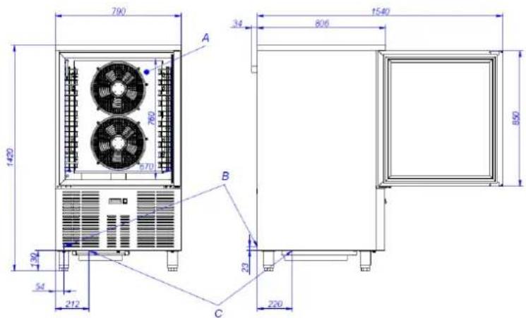
DIMENSIONES GENERALES Y ACOMETIDAS (mm) DIMENSIONS GÉNÉRALES ET BRANCHEMENTS (mm) GENERAL MEASUREMENTS AND CONNECTIONS (mm) GENERELLE MÅL OG TILSLUTNINGER (mm) YLEISMITAT JA LIITÄNTÄ (mm)
ALLGEMEINE ABMESSUNGEN UND ZULEITUNGEN (mm) DIMENSIONI GENERALI E CONNESSIONI (mm) WYMIARY OGÓLNE ORAZ PODŁĄCZENIE (mm) ALMÄNNA MÄTT OCH ANSLUTNING (mm)
| A | Evaporador | Évaporateur | Evaporator | Verdampfer | Evaporatore | Parownik | Verdamper | Lauhdutin | Avdunstare |
| B | Toma Eléctrica | Alimentation | Plug | Stromquelle | Presa elettrica | Wtyczka | Stekker | Sähköliitäntä | Kontakt |
| C | Desague | Évacuation | Drainage | Abfluss | Scarico | Drenaż | Aftappen | Poistoaukko | Avlopp |
| A | Fordamper | Förångare | Höyrystin |
| B | Prop | Kontakt | Pistoke |
| C | Afløb | Dränering | Vedenpoisto |
Fig. 2. GBC05X

text_image
790 34 706 1473 850 370 670 A B 165 23 C 450 54 245Fig. 4. GBC10X
text_image
790 34 806 1540 A 760 670 1420 B 850 132 54 212 C 23 220CARACTERISTICAS GENERALES CARACTÉRISTIQUES GÉNÉRALES GENERAL CHARACTERISTICS GENERELLE EGENSKABER YLEISOMINAISUUDET
ALLGEMEINE EIGENSCHAFTEN CARATTERISTICHE GENERALI CHARAKTERYSTYKA OGÓLNA ALLMÄNNA EGENSKAPER
Tabla 1 / Table 1 / Tableau 1 / Table 1 / Tabelle 1 / Tabella 1 / Tabela 1 / Tabel 1 / Taulukko 1 /Tabell 1
| Modelo | Gas | Tensión | Potencia frigorífica (W) | W x D x H exterior (mm) | Peso neto (kg) |
| Modèle | Gaz | Voltage | Puissance frigorifique (W) | L x P x H extérieur (mm) | Poids net (kg) |
| Model | Gas | Tension | Refrigerated power (W) | W x D x H external (mm) | Weight (kg) |
| Modell | Gas | Tensione | Kühlleistung (W) | B x H x T außen (mm) | Nettogewicht (kg) |
| Modello | Gas | Spannung | Potenza frigorifera (W) | W x D x H exterior (mm) | Peso netto (kg) |
| Model | Gaz | Voltage | Moc chłodzenia (W) | W x D x H zewnętrzne (mm) | Masa netto (kg) |
| Model | Gas | Spænding | Køleeffekt (W) | B x D x H udvendigt (mm) | Vægt (kg) |
| Modell | Gas | Spänning | Kyleffekt (W) | W x D x H yttre (mm) | Nettovikt (kg) |
| Malli | Kaasu | Jännite | Jäähdytysteho (W) | Ulkomitat W x D x H (mm) | Nettopalno (kg) |
| GBC05X | R452a | 230V 1+N | 690 | 790 x 700 x 850 | 98 |
| GBC10X | R452a | 230V 1+N | 1300 | 790 x 800 x 1420 | 160 |
ES
PANEL DE CONTROL
PANNEAU DE COMMANDE
CONTROL PANEL
KONTROLPANEL
OHJAUSPANEELI
Fig. 5
BEDIENFELD
PANNELLO DI CONTROLLO
PANEL STEROWANIA
STYRPANEL

text_image
-14.0°C SET | FNC | 12 13 14 11 10 9 8 7 6 5 4 3 2| 1 | Botón ON/OFF | ON/OFF Button | Bouton ON / OFF | Taste ON/OFF | Tasto ON / OFF | Włącznik ON/OFF | Tænd/sluk-knap | Brytare ON/OFF | ON/ OFF-kytkin |
| 2 | Ciclo controlado por temperatura | Temperatu re controlled cycle | Cycle à températur e contrôlée | Temperatu rgesteuert er Zyklus | Ciclo di temperatura | Cykl sterowany przez temperaturę | Temperatursty ret cyklus | Temperatu rstyrd cykel | Lämpötilaohj attu sykli |
| 3 | Ventilador del evaporador | Evaporato r fan | Ventilateur évaporate ur | Verdampf er-Ventilator | Ventole evaporatore | Wentylator parownika | Fordamperblæ ser | Förångarfl äkt | Höyrystimen puhallin |
| 4 | Desescarche | Defrost | Dégivrer | Abtauen | Sbrinamiento o | Odszranianie | Afrimning | Avfrostning | Sulatus |
| 5 | Compresor | Compressor | Compress eur | Kompressor | Compressor e | Kompresor | Kompressor | Kompressor or | Kompressori |
| 6 | Icono alarma | Alarm Icon | Icône d'alarme | Alarm Symbol | Icona di allarme | Ikona alarmu | Alarm ikon | Larm-ikon | Hälytyskuva ke |
| 7 | Conservació n activo | Conservati on active | Préservati on activé | Konservier ung aktiv | Conservatio ne | Konserwacja | Konservering aktiv | Underhåll | Huolto |
| 8 | Unidad medida temperatura | Temperatu re unit measure | Mesure d'unité de températur e | Maßeinheit der Temperatu r | Unita di misura temperatura | Jednostka miary temperatury | Måleenhed for temperatur | Mättenhet för temperatur | Lämpötilan mittayksikkö |
| 9 | Unidad medida tiempo | Time unit measure | Mesure d'unité de temps | Maßeinheit der Zeit | Unita di misura tempo | Jednostka miary czasu | Måleenhed for tid | Mättenhet för tid | Ajan mittayksikkö |
| 10 | Ciclo controlado por tiempo | Time controlled cycle | Cycle temporisé | Zeitgesteu erter Zyklus | Basso consume | Cykl sterowany przez czas | Tidsstyret cyklus | Tidsstyrd cykel | Aikaohjattu sykli |
| 11 | UP, desescarche manual | UP, manual defrost | UP, Dégivrage manuel | UP, manuelles Abtauen | UP, Sbrinamento | W GÓRE, manualne odszranianie | OP, manuel afrimning | UPP, manuell avfrostning | YLÖS, manuaalinen sulatus |
| 12 | DOWN, funciones adicionales | DOWN, additional functions | DOWN, fonctions supplémentaires | DOWN, zusätzliche Funktionen | DOWN, funzioni supplementary | W DÓŁ, funkcje dodatkowe | NED, ekstra funktioner | NER, ytterligare funktioner | ALAS, lisätoiminnot |
| 13 | START / STOP | START / STOP | START / STOP | START / STOP | START / STOP | START / STOP | START/STOP | START / STOPP | START / STOP |
| 14 | SET, bloqueo teclado | SET, Keypad lock | SET, verrouillage du clavier | SET, Tastatursp erre | SET, Blocco tastiera | SET, Blokada klawiatury | SET, tastaturlås | SET, Lås för knappsats | SET, Näppämistö n lukitus |

text_image
I 11. ÍNDICE
natural_image
Simple diagram of a rectangular container with curved arrows indicating flow or movement, no text or symbols present.A: CUERPO DE LA PATA
B: ROSCA:
7. RECICLAJE DEL PRODUCTO

- INDEX 17
- GENERAL INFORMATION AND WARNINGS.... 18
- PRODUCT DETAILS....19
3.1 General characteristics.... 19
- INSTALLATION INSTRUCTIONS 20
4.1 Removal of packaging 20
4.2 Positioning and levelling 20
4.3 Electrical connection....21
4.4 Drainage connection....21
4.5 Recycling 21
- USE AND MAINTENANCE INSTRUCTIONS 22
5.1 Operation 22
5.1.1 Switching on the machine....22
5.1.2 Operational cycles 22
5.1.3 Temperature probe insertion verification test 24
5.1.4 Operational state 24
5.1.5 Defrosting....24
5.1.6 Compresor and evaporator fan status checking.... 25
5.2 Useful tips 25
5.2.1 Maintenance 25
5.2.2 Prolonged non use.... 25
- FAULTS, ALARMS AND BREAKDOWNS 26
6.1 Alarms and errors 26 - RECYCLING THE PRODUCT 27
2. GENERAL INFORMATION AND WARNINGS
This manual has been created to help you understand the operation, installation and maintenance of the machine. It contains all the necessary information and warnings to ensure that the appliance is installed and used correctly, together with information about the characteristics and possibilities offered, so that you may enjoy your machine to the full.

BEFORE STARTING THE APPLIANCE, PLEASE READ THE INSTRUCTIONS CONTAINED IN THIS MANUAL CAREFULLY.
The manual should be kept safely to hand for future reference.
If the machine is sold or transferred, please pass the manual to the new user.

THIS APPLIANCE IS EXCLUSIVELY FOR PROFESSIONAL USE, AND SHOULD ONLY BE USED BY QUALIFIED PERSONNEL.
- The positioning and installation, and all repairs or modifications, should always be carried out by an AUTHORIZED TECHNICIAN, in accordance with the applicable legislation of the country. The manufacturer does not accept liability if the machine is incorrectly installed.
- The installation, incorrect adjustment, inappropriate maintenance or use of the appliance may cause material damages and injuries.

• If your machine breaks down, please call the Technical Service Centre.
• Unqualified or unauthorized personnel must NOT try to repair the machine
• Use of spare parts other than original parts will cancel the guarantee.
- During all maintenance operations, the refrigerator must be disconnected from the main power supply at the mains power switch.
- Abrasive or corrosive products, acids, solvents and chlorine-based detergents must NOT be used to clean the appliance, as this may damage the components.

FAILURE TO COMPLY WITH THESE INSTRUCTIONS OR THE INCORRECT USE OF THE APPLIANCE SHALL RELIEVE THE MANUFACTURER OF ANY OBLIGATIONS REGARDING THE GUARANTEE OR POSSIBLE CLAIMS.
3. PRODUCT DETAILS
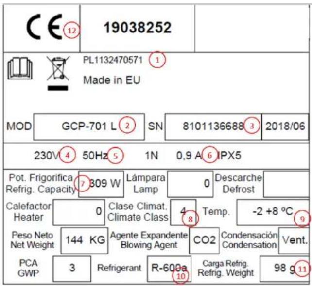
All the appliances have a specification plate which identifies it and indicates its technical characteristics; it is located on one side of the machine. Don't remove the specifications plate from the unit.
Brief introduction to the plate sticked to the machine:
text_image
CE⑫ 19038252 PL1132470571 ① Made in EU MOD GCP-701 L② SN 8101136688③ 2018/06 230V④ 50Hz⑤ 1N 0,9 A⑥IPX5 Pot. Frigorifica Refrig. Capacity ⑦ 309 W Lámpara Lamp 0 Descarche Defrost Calefactor Heater 0 Clase Climat. Climate Class 4 Temp. -2 +8 °C Peso Neto Net Weight 144 KG Agente Expandente Blowing Agent CO2 Condensación Condensation Vent. PCA 3 Refrigerant R-600a 10 Carga Refng. Refrig. Weight 98 g⑪| NÚMERO | DESCRIPCIÓN |
| 1 | MANUFACTURER |
| 2 | MODEL |
| 3 | SERIAL NUMBER |
| 4 | VOLTAGE |
| 5 | FREQUENCY |
| 6 | CURRENT |
| 7 | REFRIGERATION POWER (W) |
| 8 | CLIMATIC CLASS (N=4) |
| 9 | WORKING TEMPERATURE |
| 10 | GAS TYPE |
| 11 | GAS (gr) |
| 12 | NORMATIVE |
Note: This plate is an example; reality might differ slightly from it.
These details should be given when the technical service is called.
3.1 General characteristics
These machines have been built according to the EC directives regarding food treatment and preservation. The use of the cooler consists of lowering the temperature suddenly from a level (cooked or fresh products) to another level that guarantees the maintenance of the ideal nutritional, physical and chemical properties of the food.
It should be pointed out that the critical temperature range between 10 °C and 85 °C in the product should be passed through as fast as possible.
It has an electronic timer and chamber temperature probe. Cycle control by time or with probe in the heart of the food. When the cooling cycle finishes, it can be used as a refrigeration chamber: +2, +4 °C; or as a frozen food maintenance chamber: -18 °C, for a short period of time.
Depending on several factors and according to the prepared data, it is about advising the user about a very homogeneous and standard product in international cuisine.
| MODEL | PRODUCTIONS (kg) (*) | |
| REFRIGERATION | FREEZING | |
| GBC05X | 18 | 10 |
| GBC10X | 50 | 30 |
(*) Productions calculated according to EN17032 (Refr, +65 °C □ +10 °C in 120'; Freez. +65 °C □ -18 °C in 270')
The quantity of product can vary if the test conditions change, such as temperature.
4. INSTALLATION INSTRUCTIONS

text_image
Yellow triangular warning sign with black exclamation mark symbolThe location and installation, as well as all kind of repairs and transformation, always must be carried out by an AUTHORIZED TECHNICIAN, according to the regulation in force in each country
Installation, incorrect adjustment, service or unappropriated maintenance of the device, as well as a wrong handling of it, may cause both material damages and injuries.
4.1 Removal of packaging
Remove packaging from the machine and check if any damage during transportation. If any damage is observed, immediately notify the supplier and the transport company. In the event of doubt, do not use the machine until the problem has been assessed.

Packaging (plastic, expanded polyurethane, staples, etc...) must not be left in the reach of children, they are a potential hazard.
The cabinet should not be overturned. If necessary, some cabinets can be overturned by the side that is indicated on the packaging. If not indicated, it cannot be overturned. Wait at least 2 hours to turn the machine on since the machine is placed in the right location.
The machine should be moved using a fork-lift truck or similar to avoid damage to the structure.
Transport the machine to the installation location and then remove packaging.
All the packaging can be recycled. Dispose of packaging correctly.
4.2 Positioning and levelling
Make sure the place to store the machine is free and clean, avoiding the fan absorbing the dust nearby which might block the condenser reducing the efficiency of the machine.
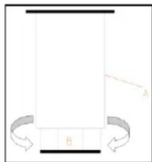
Remove the pallet carefully, avoiding any scratch to the machine. Level the machine by using the adjustable feet. Once the machine is levelled, pill the protective film off by using a no sharp knife to avoid scratches in the stainless steel.
natural_image
Pure diagram of a rectangular structure with labeled points A and B, no text or symbols presentA: BODY OF THE FEET
B: THREAD:
Rotate clock wise to lower down the machine.
Rotate counter-clock wise to elevate the machine.
The device, once it is located definitively, backside must be placed 50mm from the wall, 30mm from sides lateral and 500mm from the ceiling.
If the machine is provided with castors, make sure the floor is totally flat.
In the commissioning make sure there is no any heat source nearby.
For an optimum performance of the equipment, it is really important that all air intakes, both in the fan located inside the chamber and in the condenser, are not clogged.
Do not install the device outdoors.
Do not introduce any element from the fan protector or in the refrigeration equipment area.
4.3 Electrical connection
Electrical connection must be carried out by an AUTHORISED TECHNICIAN
The legal standards in force in each country regarding connection to the mains should be taken into account.

- Check that the mains voltage corresponds to that indicated on the nameplate.
- It is essential that the electrical installation where the cabinet is going to be connected has an GROUNDING SOCKET, in addition to the appropriate magneto-thermal switch and differential protection (we recommend 30 mA)
- The appliance must be grounded using a differential protector. The manufacturer will not be held liable for damage originated by failure to observe this requirement.
- The cross-section of the power cable must be suitable for the rated current of the machine.
- The plug should be Schuko type with grounding and terminals of 4.8mm (F type). It is forbidden to enlarge the plug for your safety. As optional, the equipment can be supplied with British type plugs (H type) or American type plugs (B type).
- If any faults are observed during the installation, the supplier should be notified immediately.
- Do not install the Blast Chiller outdoors.
- In case of fire do not use water. Use CO2 (carbon dioxide) extinguishers and cool the engine area as fast as possible.

The manufacturer will not be held liable for any personal or material damage to the machine resulting from incorrect installation or failure to comply with the manufacturer's specifications.
The electric specifications of the machine are shown in the specification plate. Section 3.
4.4 Drainage connection
If you want to place the drain in a fixed and definitive location, it must be connected to a general drain, creating a siphon with said drain to avoid cold losses. This operation must be carried out by qualified personnel. See Figures 1 - 4 for the location of the drain.
4.5 Recycling
The product packaging consists of:
- A wooden pallet.
- Cardboard.
- A polypropylene band.
- Expanded polystyrene.

All the packaging used around the machine can be recycled; The correct disposal of these products will help to protect the environment. For further information regarding the recycling of these products, please refer to the relevant office of the local body. Dispose of these materials in accordance with current legislation.
5. USE AND MAINTENANCE INSTRUCTIONS

BEFORE STARTING THE APPLIANCE, PLEASE READ THE INSTRUCTIONS CONTAINED IN THIS MANUAL CAREFULLY.

THE APPLIANCE IS EXCLUSIVELY FOR PROFESSIONAL USE, AND SHOULD ONLY BE USED BY QUALIFIED PERSONNEL.
5.1 Operation
The steps required to optimize the operation of your machine are shown below, with all the available options.
5.1.1 Switching on the machine
The control panel has an On/ Off switch and one thermostat. In the Figure 5 you can see them in detail.
- Once the interior of the cabinet has been cleaned, connect it to the electrical network and turn the switch (1, Fig.5) to ON. The switch must be illuminated.
- If the appliance is on and no cycle is running, the DISPLAY (Fig.5) shows the temperature of the chamber.
- If there is no active cycle, after 10 seconds without any icon being pressed, DISPLAY (Fig.5) will automatically turn off, except for the low consumption LED. To turn the display on again, press any icon.
- If there is 60s elapse time without any icon being pressed, the display will show "Loc" and the keyboard will automatically lock. To unlock the keyboard, press any icon for 1 second. The display will show "UnL".
5.1.2 Operational cycles
The blast chiller you have adquired is controlled by an electronic timer with a chamber temperature probe, which allows 2 blast chilling methods. First one, time controlled cycle, in which the blast chilling cycle ends once the time defined for the process has elapsed and second one, temperature controlled cycle, whose process ends, once the temperature sensor inserted in the food reaches the defined temperature.
In turn, there are 2 blast chilling processes, depending on the final temperature to be reached, refrigeration and freezing, which can be accessed by pressing the SET button (14, Fig.5).
 | Press SET button to select a cycle | |
| PoS |  | Refrigeration, time controlled cycle |
| nEG |  | Freezing, time controlled cycle |
| PoS |  | Refrigeration, temperature controlled cycle. |
| nEG |  | Freezing, temperatura controlled cycle |
 | Press START/STOP button in the following 15 seconds. | |
5.1.2.1 Time controlled chilling cycle
To run a time controlled blast chilling cycle follow these steps:
- Make sure that the keyboard is not locked and that no chill or defrost cycle is active.
-
Press SET button (14, Fig.5) to choose between a refrigeration chilling process "PoS" or freezing chilling process "nEG" and ensure that the TIME CONTROLLED CYCLE icon (10, Fig.5) blinks. By default, refrigeration cycle lasts 90 minutes, while freezing cycles lasts 240 minutes.
-
OPTIONAL: Parameters related with cycle duration, setpoint of the chilling cycle and conservation cycle setpoint can be adjutasted.
Press button DOWN FNC (12, Fig.5), before 15 seconds and press button SET (14, Fig.5)
to see default cycle duration and modify it. In order to change the value press UP (11, Fig.5) or DOWN (12, Fig.5). Press again SET button (14, Fig.5) to exit and continue to the next step.
To check and modify the set point of the chilling process, press DOWN button (12, Fig.5), before
15 seconds and press SET (14, Fig.5). In order to change the value press UP 📄 (11, Fig.5) or DOWN (12, Fig.5). Press again SET button (14, Fig.5) to exit and continue to the next step.
To check and modify the set point of the conservation cycle, press DOWN button (12, Fig.5), before 15 seconds and press SET (14, Fig.5). In order to change the value press UP (11, Fig.5) or DOWN (12, Fig.5). Press again SET button (14, Fig.5) to exit and continue to the next step.
This is a temporary adjustment. When activating a new cycle or when a power failure occurs, these values are reset to those defined by the manufacturer.
- Press START/STOP (13, Fig. 5), the cycle will run and TIME CONTROLLED CYCLE icon (10, Fig.5) will light up.
During the chilling process, the DISPLAY will show remaning cycle time. When the cycle time is over, the DISPLAY will show the word "END" and the buzzer will be activated during the time specified on "AA" parameter. To mute the buzzer press any icon.
Finally, once process finishing is indicated, conservation process is activated lightning up CONSERVATION (7, Fig.5) icon and chamber temperature is shown in the DISPLAY.
Additionally, during chilling cycle, it is possible to show the chamber temperature in the display. Press DOWN button (12, Fig.5), choose the chilling option which is in force "PoS" for refrigeration or "nEG" for frezzer. Once the cycle is chosen, press again DOWN button (12, Fig.5) to show this value. To exit the process, press SET button (14, Fig.5) or do not take any further action for the following 15 seconds.
In order to interrupt a chilling process, press START/STOP (13, Fig. 5), for 2 seconds.
5.1.2.2 Temperature controlled chilling cycle
To run a time controlled blast chilling cycle follow these steps:
- Make sure that the keyboard is not locked and that no chill or defrost cycle is active.
- Press SET □ SET button (14, Fig.5) to choose between a refrigeration chilling process "PoS" or freezing chilling process "nEG" and ensure that the TEMPERATURE CONTROLLED CYCLE 📁 icon (2, Fig.5) blinks. By default, food temperature probe set point for refrigeration cycle is set in 3°C, while for freezing cycle is defined in -18°C.
- Before a temperature controlled cycle starts, an automatic test is carried out, in order to check that the temperature sensor is correctly inserted into the food to be chilled. If test fails, corresponding time controlled cycle starts.
- OPTIONAL: Parameters related with the temperature probe value at the end of chilling cycle, maximum cycle duration time, chamber setpoint during chilling cycle and chamber setpoint on conservation cycle can be adjutasted.
Press button DOWN FNC (12, Fig.5), before 15 seconds and press button SET (14, Fig.5) to check the product final temperature value and modify it. The value can be changed by pressing UP (11, Fig.5) or DOWN FNC (12, Fig.5) buttons. Press SET to come back to previous level.
In order to watch and modify chilling cycle maximum duration press DOWN (12, Fig.5), button again in a period not exceeding 15 seconds and press SET (14, Fig.5) button again. Press UP (11, Fig.5) or DOWN (12, Fig.5) buttons to change the value. Press SET (14, Fig.5) to come back to previous level.
In order to watch and modify chamber temperature set point during chilling process press DOWN (12, Fig.5), button again in a period not exceeding 15 seconds and press SET button again. Press UP (11, Fig.5) or DOWN (12, Fig.5) buttons to change the value. Press SET (14, Fig.5) to come back to previous level.
☐ In order to watch and modify the set point during conservation process press DOWN (12, Fig.5), button again in a period not exceeding 15 seconds and press SET (14, Fig.5) button again. Press UP (11, Fig.5) or DOWN (12, Fig.5) buttons to change the value. Press SET (14, Fig.5) to come back to previous level.
This is a temporary adjustment. When activating a new cycle or when a power failure occurs, these values are reset to those defined by the manufacturer.
- Press START/STOP (13, Fig. 5), the cycle will run and TIME CONTROLLED CYCLE icon (10, Fig.5) will light up.
If the temperature detected by food temperature probe reaches cycle set point, before maximum duration time has been reached, "EnD" word will be displayed on the screed, buzzer will be activated during the period established on "AA" parameter and the devices will go on conservation mode. Press any button to mute the buzzer and press again another button to remove "EnD" indicator.
EN
If the temperature detected by food temperature prove does not reach cycle set point, when maximum cycle duration time has been reached, the cycle will continue till the set temperature is reached. Then,
TEMPERATURE CONTROLLED CYCLE (2, Fig.5). icon will blink and ALARM (6, Fig.5) will light up and buzzer will be active. Press any button to mute the buzzer.
Finally, once the cycle process ending is indicated, if the chilling has bee successful, the device goes on conservation mode lightning up CONSERVATION (7, Fig.5) icon together with
TEMPERATURE CONTROLLED CYCLE (2, Fig.5). On the oppsite, if the cycle has failed, ALARM (6, Fig.5) icon will lift up. While this status last, compartment temperature will be displayed on the screen.
In addition, during conservation, if the process has been successful, the elapse between real cycle time and default maximum cycle duration time can be checked. Whereas, if the process failed, the elapse of time between the maximum cycle duration and the instant when the food temperature probe detects the set point can be displayed. For both cases, press DOWN (12, Fig.5) button. Press DOWN DOWN
(12, Fig.5) button, once again so as to display chamber temperature and press SET ⚠ SET (14, Fig.5), button to exit the application.
To interrupt chilling process in any of its state, press START/STOP (13, Fig. 5), button for 2 seconds.
5.1.2.3 Start a cycle with the same program as the last cycle started
Make sure that the keyboard is not locked. Press SET ⏻ SET (14, Fig.5) button. Last carried out type of cycle will be displayed. Press SET (14, Fig.5) button in the following 15 seconds.
5.1.3 Temperature probe insertion verification test
Set-temperature cycles are preceded by a test step in order to check correct pin probe insertion.
The test has two stages:
- The outcome of the first stage is positive if "the temperature measured by the pin probe - the temperature of the cabinet" is greater than the value set by parameter rc at least 3 times out of 5 (the comparison is made every 10 s), if parameter rc is set to 0, neither the first nor second stages will be run.
If the outcome of the first stage is positive, the second will not be run
- If the outcome of the first stage is negative, the second will be run. The outcome of the second stage is positive if the difference “temperature measured by the pin probe - temperature of the cabinet” is greater by at least 1^ C/ 1^ F (with respect to the previous comparison) at least 6 times out of 8 (the comparison is made every “rd/8 s”).
If the outcome of the test is positive, the cycle will be activated.
If the outcome of the test isn't positive, the cycle will be started in timed mode and icon (2, Fig.5)
If power is interrupted during the test, when power is restored, the test will start again from the beginning.
5.1.4 Operational state
"ON" STATUS
The device is switched on but operating cycle is running, If power is interrupted:
- During a timed blast chilling operation, when power is restored, chilling will continue from the time point at which the interruption occurred (with a maximum error of 10 minutes);
- During a set-temperature blast chilling operation, when power is restored, chilling will start again from the beginning;
• During a storage operation, when power is restored the storage operation will be reset.
"STAND-BY" STATUS
- The device is switched on but no operating cycle is running. If power is interrupted while in "stand-by" mode, when power is restored the device will be in the same state.
5.1.5 Defrosting
The blast chiller you have adquired only has a manual defrost process. The food that is introduced into the appliance, as well as the opening of doors, generate humidity inside the machine. When performing a blast chilling cycle, this moisture condenses and freezes at the coldest point of the blast chiller, which is the evaporator, accumulating ice. In some cases, this accumulation might cause evaporator blocking
EN
and subsequently chilling cycles are not carried out correctly. For this reason, it is advisable to carry out a defrost process from time to time, especially if several chilling cycles are performed consecutively.
In order to start a defrosting cycle, make sure that no other procedure is in use, open the door and press
UP/DEFROST (11, Fig.5) button for 4 seconds.

The duration of the defrost can be configured with parameters d3 and d7. Contact your technical service for modification.
5.1.6 Compresor and evaporator fan status checking
In order to check the statur of the compressor, ensure ther eis no other cycle active. Press DOWN FNC (12, Fig.5) button once and the status of the compressor will be displayed as follows:
• "C-1", the compressor is switched-on
• "C-0", the compressor is switched off
- “C-P”, compressor protection active (parameters C0, C1, C2 and i7).
To check the statur of evaporator fan, press FNC (12, Fig.5) button once again and the status of the fan will be displayed as follows:
• "F-1", the evaporator fan will be switched on
• "F-0", the evaporator fan will be switched off
- “F-P”, then evaporator fan deferred activation will be ongoing (parameter F8).
To exit the procedure, Press SET SET (14, Fig.5) button or do not take any further action for the following 15 seconds.
5.2 Useful tips
Read carefully the below advices so as to reach the full potential of the refrigeration cabinet.
5.2.1 Maintenance
Carry out necessary cleaning operation in order to enlarge the service life of the machine.
- Remove any waste from the machine at the end of each day. Before cleaning the machine, unplug the machine from the electricity supply and put the switch in OFF or O position. The appliances include a drainage in the bottom of refrigerated chamber (Except 3 trays models), to help the cleaning operation, as well as the eventual output of liquids from food. During the cleaning operation it is essential to remove the drain plug and clean it, to prevent clogging by solid elements. It prevents accumulated liquids from stagnating.
- Do not use abrasive, corrosive or acid products, chlorine-based detergents, solvents or petrol derivatives to clean the machine.
- Do not use pressurized water to clean the machine.
- Take precautions before accessing to the unit condenser zone, due to the high temperatures there might be risk of burns
- Cleaning the condenser: During cleaning, avoid any bending of the condenser aluminum fins. It could affect on the condenser air circulation, causing serious damage to the equipment, being the repair out of warranty in that case.
- Check that the doors close perfectly.
• If any change of wires is needed, do not change for a lower section one - The assembly of the electrical installation cover in the control panel is important. If disassembling is needed, it must be tightened back as it was.
• Twice a year call the technical service to carry out the relevant revisions: - Review of the status of the joints.
- Review of the state of the components.
- If the wire is damaged, it should be replaced by the manufacturer, its after sales service department or by an autorized technical to avoid any personal or equipment damage.
5.2.2 Prolonged non use
If the machine is kept out of service for a long period of time (holidays, temporary closure...), please observe the following:
- Clean the equipment carefully.
- Switch off the mains power supply.
EN
6. FAULTS, ALARMS AND BREAKDOWNS
The steps to be followed in the event of a fault or operating error are described below. The possible causes and possible solutions are listed in the following table. In the event of doubt, or if you are unable to resolve the problem, please contact the technical service.

Do not handle electrical components, as there is a risk of death as the components are under network voltage.
| FAULT | POSSIBLE CAUSE | SOLUTION |
| Blast chiller does not work | There is no power supply. | Check whether the circuit breaker has been triggered. If there is light in the switch the machine is powered. |
| Insufficient temperature | Location of the equipment | Check there is not a heat source nearby |
| Ambient temperature | Check that ambient temperatura is below +32°C in freezer cabinets and +38 °C in refrigeratios and fish storage cabinets. These are devices guaranteed maximum working temperature | |
| Door closing | Check that the doors close correctly | |
| Food distribution inside the machine | Check that food does not block the air ventilation and the time elapsed from the time the food is stored inside the cabinet is enough for cooling the products. | |
| Cleaning of the condenser | Check that the condenser is clean. Consider that the cleaner the refrigerator is the more energy will be saved. The cleaning frequency will depend on the conditions of the location. In case the condenser is dirty call after sales service. | |
| Strange or loud noise | Incorrect levelling and bad closing of the doors. | Check the levelling and good closing of the doors. |
| Friction in the movable zones | Check there is nothing in touch with the movable elements of the refrigerator. |

NOTE: If a fault occurs and is not listed in the above table, please call the technical service. The manufacturer reserves the right to modify the technical characteristics with prior warning.
Together with this manual, it is supplied the instructions of the thermostat.
6.1 Alarms and errors
| COD. | MEANING | SOLUTIONS | CONSEQUENCES |
| AL | Minimum temperature alarm | Check the cabinet temperatureCheck Parameters A1 and A2 | The device will continue to function normally |
| AH | Maximum temperature alarm | Check the cabinet temperatureCheck Parameters A3 and A4 | The device will continue to function normally |
| id | Door switch alarm input alarm(Only in “stand-by” mode and if parameter i0 is set to 0 or 1) | Close the doorCheck the causes which activated the input.Check parameters i0 and i1 | The evaporator fan will stay hold until alarm ends |
| iA | Compressor protection input alarm(Orly if parameter i0 is set to 2) | Check the causes which activated the input. Check parameters i0 and i1 | Compressor + evaporator fan stop working |
| Pr1 | Cabinet probe error | See PO parameterCheck probe integrityCheck probe-device connectionCheck the cabinet temperature | If the error occurs while in "Stand by" mode:If parameter C11 = 0 no cycle will be allowed to startIf parameter C11 = 1. Pin probe will work as cabinet probe and only time cycle will be allowed. |
| If the error occurs during time controlled cycle:- If parameter C11 = 0, cycle will be interrupted- If parameter C11 = 1, pin probe will work as cabinet probe and the chilling operation will continue. | |||
| If the error occurs during a temperature controlled cycle:- If parameter C11 = 0, cycle will be interrupted- If parameter C11 = 1, the pin probe will work as cabinet probe and the chilling operation will continue | |||
| If the error occurs during conservation mode:- If parameter C11 = 0, compressor activity will depend on C4, C5 y C6 parameters.- If parameter C11 = 1, the pin probe will work as cabinet probe and the storage operation will continue. | |||
| Pr2 | Pin probe error | See PO parametCheck probe integrityCheck probe-device connectionCheck the cabinet temperature | If the error occurs during “Stand by” mode:- Only tied operation cycles will be allowed to start. |
| If the error occurs during a time controlled cyle:- Chilling will continue | |||
| If the error occurs during temperature controlled cycle:- Chilling will continue in time mode | |||
| If the error occurs during conservation mode:- Conservation mode will continue. |
7. RECYCLING THE PRODUCT

The European Directive 2012/19/EU relating to Waste Electrical and Electronic Equipmen (WEEE) states that household appliances should not be disposed of using the normal solid urban waste cycle. Exhausted appliances should be collected separately in order to optimise the cost of re-using and recycling the materials inside the machine, while preventing potential damage to the atmosphere and to public health. The crossed-out dustbin is marked on all products to remind the owner of their obligations regarding separated waste collection. For more information, relating to the correct disposal of household appliances, owners should contact their local authorities or appliance dealer.
FR
1. SOMMAIRE
- SOMMAIRE 28
- INFORMATIONS ET AVERTISSEMENTS GÉNÉRAUX 29
- CARACTÉRISTIQUES DU PRODUIT.... 30
text_image
Yellow triangular warning sign with black exclamation mark symbolnatural_image
Simple diagram of a container with two side handles and an arrow labeled A pointing to the top section (no text or symbols beyond labels)A : CORPS DU PIED
B : VIS :
"STATUT "ON" (MIS EN MARCHE)
STATUT "STAND-BY" (MODE VEILLE)
7. RECYCLAGE DU PRODUIT
text_image
Yellow triangular warning sign with black exclamation mark symbolnatural_image
Pure diagram of a rectangular container with side handles and internal components, no text or symbols presentA: KÖRPER DES FUSSES
B: GEWINDE:
5.1.4 Operational state
STATUS "ON"
natural_image
Symbol of a trash bin with crossed lines indicating no waste or discharge, and a solid black rectangle below (no text or labels)text_image
Yellow triangular warning sign with black exclamation mark symbolnatural_image
Pure diagram of a rectangular container with curved arrows indicating flow or movement, no text or symbols present.A: CORPO DELLA GAMBA
B: FILETTATURA:
text_image
Yellow triangular warning sign with black exclamation mark, commonly used to indicate a hazard or alert event.natural_image
Pure diagram of a rectangular structure with curved arrows indicating rotation, no text or symbols presentA: KORPUS NÓŻKI
B: GWINT
5.1.1 Switching on the machine
5.1.2 Operational cycles
5.1.2.1 Time controlled chilling cycle
STAN "ON" (WŁĄCZONY)
text_image
Yellow triangular warning sign with black exclamation mark symbolnatural_image
Simple diagram of a container with arrows indicating flow or movement, no text or symbols presentA: F∅DDERNE
B: TRÅD:
1. INNEHÅLLSFÖRTECKNING
- INNEHÅLLSFÖRTECKNING....86
- ALLMÄN INFORMATION OCH VARNINGAR....87
- PRODUKTSPECIFIKATIONER....88
text_image
Yellow triangular warning sign with black exclamation mark symbol"ON"-STATUS (PÅSLAGEN)
6. AVVIKELSER, LARM OCH FEL
text_image
Yellow triangular warning sign with black exclamation mark symbolAccess to professional repair, such as internet webpages, addresses, contact details.
Model no: GBC05X
Aftersales service station list:
| Address | Scandomestic A/S |
| Contact Number | 7242 5571 |
| Website | Scandomestic.dk |
| QR code | |
| Relevant information for ordering spare parts, directly or through other channels provided by the manufacturer, importer or authorised representative; | Scandomestic A/S |
| The minimum period during which spare parts, necessary for the repair of the appliance, are available; | 8 years |
| Instruction on how to find the model information in the product database, as defined in Regulation (EU) 2019/2019 by means of a weblink that links to the model information as stored in the product database or a link to the product database and information on how to find the model identifier on the product.) | www.scandomestic.dk |
Note: The address or contact phone number of the service site is subject to change without prior notice. Please confirm whether the service station is a directly affiliated one of our company when requiring services.
DE
Access to professional repair, such as internet webpages, addresses, contact details.
Model no: GBC10X
Aftersales service station list:
| Address | Scandomestic A/S |
| Contact Number | 7242 5571 |
| Website | Scandomestic.dk |
| QR code | |
| Relevant information for ordering spare parts, directly or through other channels provided by the manufacturer, importer or authorised representative; | Scandomestic A/S |
| The minimum period during which spare parts, necessary for the repair of the appliance, are available; | 8 years |
| Instruction on how to find the model information in the product database, as defined in Regulation (EU) 2019/2019 by means of a weblink that links to the model information as stored in the product database or a link to the product database and information on how to find the model identifier on the product.) | www.scandomestic.dk |
Note: The address or contact phone number of the service site is subject to change without prior notice. Please confirm whether the service station is a directly affiliated one of our company when requiring services.
DE
EU DECLARATION OF CONFORMITY
Ref. Ares In accordance with EN ISO 17050-1:2004
| Model number (unique identification of the product): | GBC05X |
| Name and address of the manufacturer or his authorised representative: | Scandomestic A/SLinåvej 208600 SilkeborgDenmark |
| This declaration of conformity is issued under the sole responsibility of the manufacturer (or installer): | Scandomestic A/SLinåvej 208600 SilkeborgDenmark |
| Object of the declaration (identification of product allowing traceability. It may include a colour image of sufficient clarity to enable the identification of the product)Product: Blast ChillerBrand: ScancoolColour: Stainless Steel |  |
| The object of the declaration described in point 4 is in conformity with the relevant Union harmonisation legislation: | 2006/42/EC, 2014/30/EU, 2004/108/EC, 89/336/EEC and its amendments 92/31/EEC and 93/68/EEC, EN 55014-1:2006 +A1:2009 +A2:2012, EN 61000 -3-2:2014, en 61000-3-3:2013, EN 55014-2:2015, 2014/35/Ue, 2006/95/EC, 73/23/EEC and its amendment 93/68/EEC, EN 60335-2-89:2010 + A1:2016 + A2:2017, EN 60335-1:2012 + AC:2014 + A11:2014 + A12:2017 + A13:2017, EN 62233:2009, 1095/2015//EC, 2011/65/EU, RoHS, 2015/863/EU, 1907/2006/EU, REACH |
| References to the relevant harmonised standards used, or references to the specifications in relation to which conformity is declared: | EN 61000-3-2 |
| Additional information: | The appliance is intended exclusively for storing and cooking food |

EU DECLARATION OF CONFORMITY
Ref. Ares In accordance with EN ISO 17050-1:2004
| Model number (unique identification of the product): | GBC10X |
| Name and address of the manufacturer or his authorised representative: | Scandomestic A/SLinåvej 208600 SilkeborgDenmark |
| This declaration of conformity is issued under the sole responsibility of the manufacturer (or installer): | Scandomestic A/SLinåvej 208600 SilkeborgDenmark |
| Object of the declaration (identification of product allowing traceability. It may include a colour image of sufficient clarity to enable the identification of the product)Product: Blast ChillerBrand: ScancoolColour: Stainless Steel |  |
| The object of the declaration described in point 4 is in conformity with the relevant Union harmonisation legislation: | 2006/42/EC, 2014/30/EU, 2004/108/EC, 89/336/EEC and its amendments 92/31/EEC and 93/68/EEC, EN 55014-1:2006 +A1:2009 +A2:2012, EN 61000 -3-2:2014, en 61000-3-3:2013, EN 55014-2:2015, 2014/35/Ue, 2006/95/EC, 73/23/EEC and its amendment 93/68/EEC, EN 60335-2-89:2010 + A1:2016 + A2:2017, EN 60335-1:2012 + AC:2014 + A11:2014 + A12:2017 + A13:2017, EN 62233:2009, 1095/2015//EC, 2011/65/EU, RoHS, 2015/863/EU, 1907/2006/EU, REACH |
| References to the relevant harmonised standards used, or references to the specifications in relation to which conformity is declared: | EN 61000-3-2 |
| Additional information: | The appliance is intended exclusively for storing and cooking food |