SPA-5000 - Air Conditioning Mestic - Free user manual and instructions
Find the device manual for free SPA-5000 Mestic in PDF.
User questions about SPA-5000 Mestic
0 question about this device. Answer the ones you know or ask your own.
Ask a new question about this device
Download the instructions for your Air Conditioning in PDF format for free! Find your manual SPA-5000 - Mestic and take your electronic device back in hand. On this page are published all the documents necessary for the use of your device. SPA-5000 by Mestic.
USER MANUAL SPA-5000 Mestic
text_image
Vehicles up to 6 m 5100 BTU/h (1495 W) mestic 55 dB Mode 3 speeds 24.5 kg Relax... it's mestic® mesticGebruiksaanwijzing NL User instructions EN Bedienungsanleitung DE Mode d'emploi FR
Instrucciones de uso ES Istruzioni per l'uso IT Betjeningsvejledning DK
Bruksanvisning SE Bruksanvisning NO
Inhoudsopgave
text_image
ACN1 MAIN BOARD ACN3 FAN ACL COMP. CN2 WATER2 PT RT coil sensor room sensor LED DISPLAY water pump blue Brown Blue GN/YW L N E Blue Red Black Yellow White Fan Motor Terminal Board L C N Red Brown White Fan Motor GN/YW Blue Red C Black S COMP. R Blue GN/YW Water Level Sensor4. Paklijst
natural_image
Diagram showing a mechanical assembly before and after transformation, with no visible text or symbolstext_image
Technical diagram showing three-step assembly of a mechanical bracket with labeled parts and cross-sectional viewstext_image
Drain power Drain power Drain pipenatural_image
Technical line drawing of a door lock assembly showing part assembly and mounting (no text or symbols)- Safety regulations
- Technical data
- Electric scheme
- Packing list
- Designation of parts
- Installation of the air conditioner
- Operation manual
- Connecting the device to the app
- Error code list
- Troubleshooting guide
- Maintenance
Correct disposal of this product
Declaration of conformity
1. Safety regulations
Warning
When using this air conditioner, it is important that you always observe the safety regulations. This prevents the risk of personal injury, electric shock and product damage. Therefore, read all instructions beforehand
- Read the manual before use.
- If the terms of use are not followed, the manufacturer will not be liable for any damage or injury resulting from the use of this device.
- Keep the manual, warranty certificate and sales receipt.
- Children should be supervised to ensure that they do not play with the appliance.
- This appliance is not intended to be used by children under 8 years of age or by persons with limited physical, sensory or mental capabilities or insufficient experience and knowledge, unless they have been accompanied or have been instructed on how to use the appliance by a person who is responsible for their safety.
- Never use the appliance if it is visibly damaged or if there are breaks in the cord.
- Never repair the device yourself if the appliance, the cord or the plug is damaged. Always have this done by the manufacturer or a qualified technician.
- The device is not suitable for commercial use.
• Always use and store the device in a dry place. - Never use accessories that are not recommended by the manufacturer.
- This appliance is only suitable for household use and for the purpose for which it is intended.
- It is prohibited to modify this product (or parts of it).
• Never connect multiple electrical appliances to a power outlet. This prevents a bad connection and high heat load. - It is forbidden to place the portable air conditioner (indoor & outdoor unit) in the rain or in the water
Warnings
- Distance to burning objects at least 2 meters due to fire prevention measures.
- Users are strictly forbidden to add refrigerant themselves.
- Do not pull directly on the hose or destroy it with sharp objects. If the hose is found to be damaged, discontinue use and contact the distributor for repair.
Installation location of the air conditioner
The air conditioner must be placed on a firm, flat surface (note: the air conditioner must not be tilted or tilted) when the appliance is in use. This mobile air conditioner may not be installed in the following places:
- Near strong heat sources, vapors and flammable or explosive gas.
- In an environment that contains chemicals (evaporating substances, organic solvents, etc.)
- In a wet environment. As soon as it rains, the air conditioning must be removed from the window.
- For outdoor use, the air conditioner must be kept away from rain and / or water.
Also take the following regulations into account:
- The product must be kept upright at all times and in all cases. Do not hold the device sideways or upside down.
- Try to keep the air conditioner straight when moving or carrying it. Make sure it is not shaken or dropped.
- Make sure the air supply is not clogged and remains well ventilated.
- Do not insert objects through the openings of the air inlet and outlet. Objects can come into contact with electrical parts or the fan in this way and could be dangerous.
- Do not place heavy objects on the product.
- Remove the plug from the socket before moving the air conditioner, performing maintenance, cleaning or not using it for a long time.
- Do not pull the plug to move the machine.
- Clean the dust screen of the air supply at least once a month.
- If the machine will not be used for a long time, it must be stored in a cool and dry place. Clean and dry the air conditioner well in advance.
2. Technical data
| Voltage 220~240V 50/60Hz Air flow capacity 300-350 m3/h | |||
| Cooling capacity 5100 BTU (1495 W) Dehumidification capacity 1,56 L p/u | |||
| Power 600 W Insulation class IPX4 | |||
| Refrigerant R290(120g) Compressortype Rotor type | |||
| Dimensions inside unit 45.4 X 30.8 X 20.4cm Noise 55 dB | |||
| Dimensions outside unit 44.3 X 37.3 X 20.1cm Weight 24,5 kg | |||
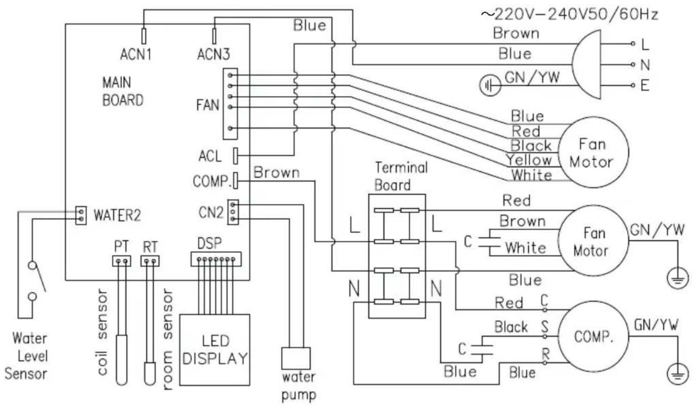
3. Electric scheme
text_image
ACN1 MAIN BOARD ACN3 FAN ACL COMP. CN2 WATER2 PT RT coil sensor room sensor LED DISPLAY water pump blue Brown Blue GN/YW L N E Blue Red Black Yellow White Fan Motor Terminal Board L C N Red Brown White Fan Motor GN/YW Blue Red C Black S COMP. R Blue GN/YW Water Level Sensor4. Packing list
| Name QTY | |
| Inner unit 1 | |
| Outside unit 1 | |
| Drain hose 1 | |
| Outside Bracket 2 | |
| Inner Bracket 2 | |
| Storage bracket 2 | |
| Shock resistant rubber blocks 2 | |
| Support blocks 2 | |
| Hand screws 14 | |
| Twist lock 2 | |
| Slotted nut 2 | |
| User's manual 1 |
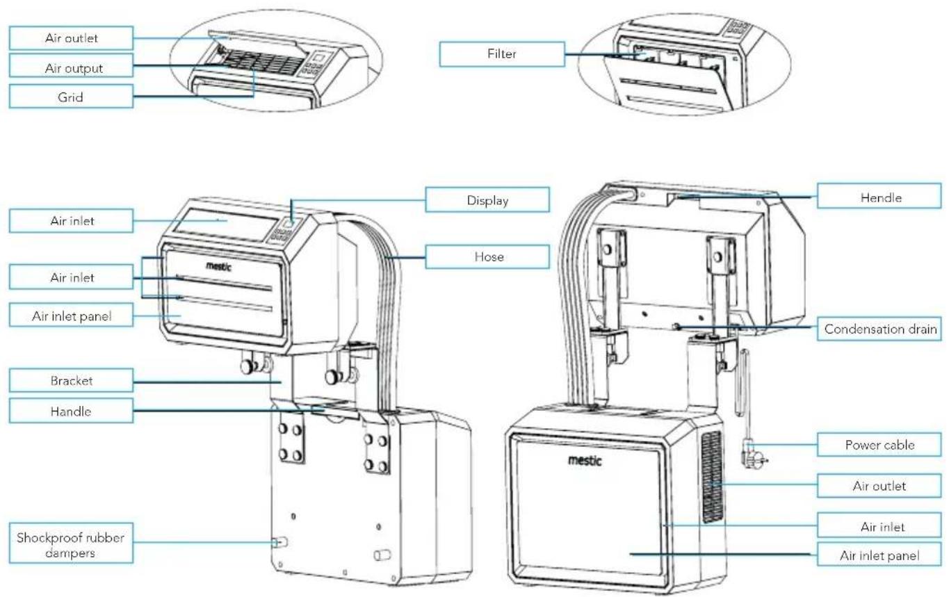
5. Parts
text_image
Air outlet Air output Grid Filter Display Hendle Air inlet Air inlet Air inlet panel mestic Hose Condensation drain Bracket Handle mestic Power cable Air outlet Air inlet Air inlet panel Shockproof rubber dampersAccessories
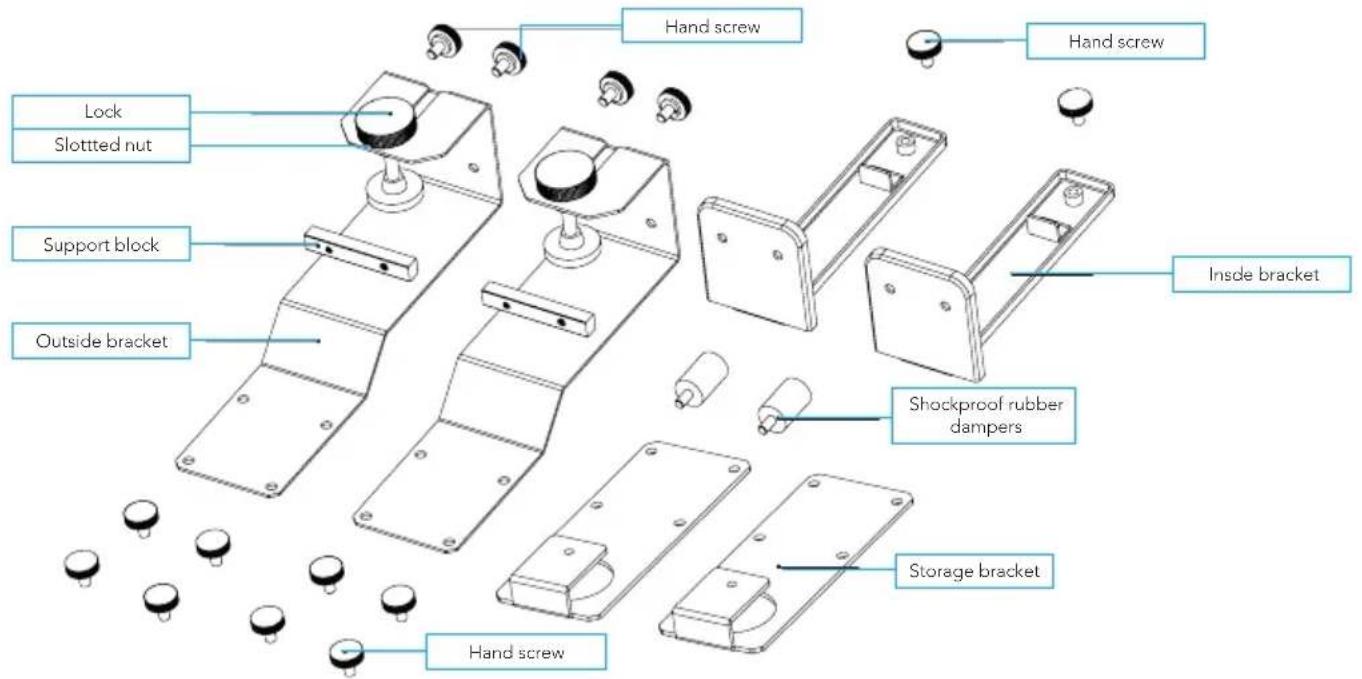
text_image
Hand screw Hand screw Lock Slotted nut Support block Outside bracket Inside bracket Shockproof rubber dampers Storage bracket Hand screwControl panel

flowchart
graph TD
    A["Digital display"] --> B["Low wind speed Wi-Fi connection"]
    A --> C["Middle wind speed Ventilate"]
    A --> D["High wind speed Airconditioner module"]
    A --> E["Night modus Modus"]
    A --> F["Wind speed On / off"]
    B --> G["+"]
    C --> H["-"]
    D --> I["+"]
    E --> J["+"]
    F --> K["+"]
    G --> L["+"]
    H --> M["+"]
    I --> N["+"]
    J --> O["+"]
    K --> P["+"]
    L --> Q["+"]
    M --> R["+"]
    N --> S["+"]
    O --> T["+"]
    P --> U["+"]
    Q --> V["+"]
    R --> W["+"]
    S --> X["+"]
    T --> Y["+"]
    U --> Z["+"]
    V --> AA["+"]
    W --> AB["+"]
    X --> AC["+"]
    Y --> AD["+"]
    Z --> AE["+"]
    AA --> AF["+"]
    AB --> AG["Increase temperature Decrease temperature"]
    AC --> AH["Increase temperature Decrease temperature"]
    AD --> AI["Increase temperature Decrease temperature"]
ENGLISH
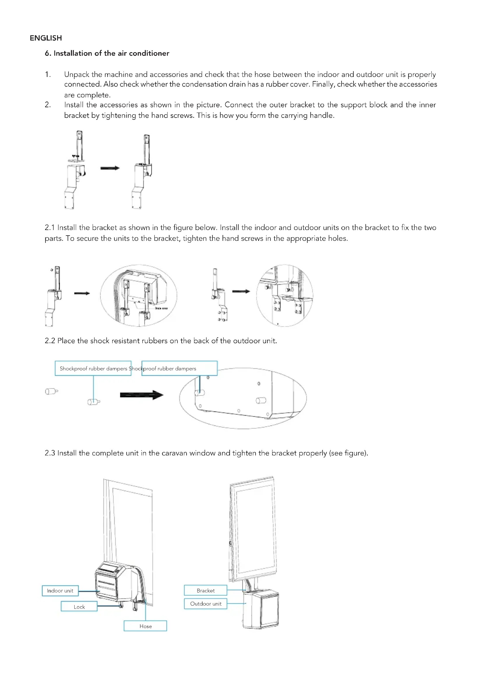
6. Installation of the air conditioner
- Unpack the machine and accessories and check that the hose between the indoor and outdoor unit is properly connected. Also check whether the condensation drain has a rubber cover. Finally, check whether the accessories are complete.
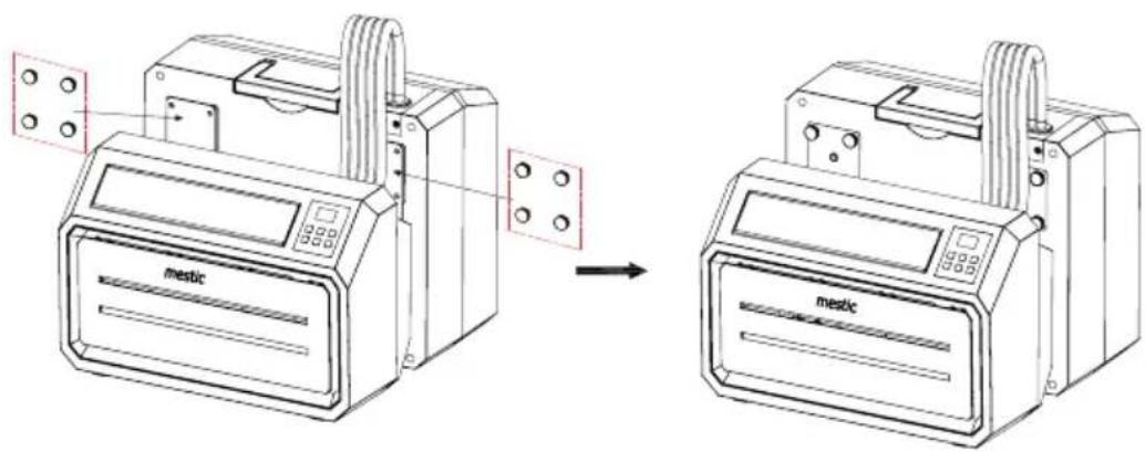
- Install the accessories as shown in the picture. Connect the outer bracket to the support block and the inner bracket by tightening the hand screws. This is how you form the carrying handle.
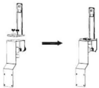
natural_image
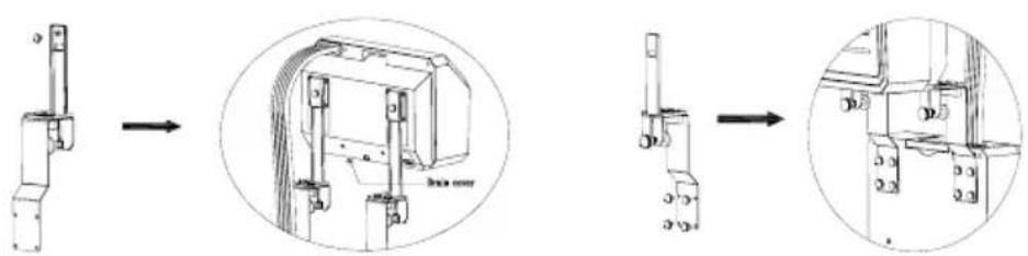
Diagram showing a mechanical assembly before and after transformation, with no visible text or symbols2.1 Install the bracket as shown in the figure below. Install the indoor and outdoor units on the bracket to fix the two parts. To secure the units to the bracket, tighten the hand screws in the appropriate holes.
text_image
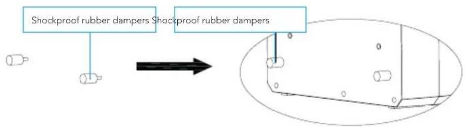
Technical diagram showing a mechanical assembly with three stages: step, cross-section, and final detail view.2.2 Place the shock resistant rubbers on the back of the outdoor unit.
flowchart
graph TD
    A["Shockproof rubber dampers"] --> B["Arrow"]
    C["Shockproof rubber dampers"] --> D["Arrow"]
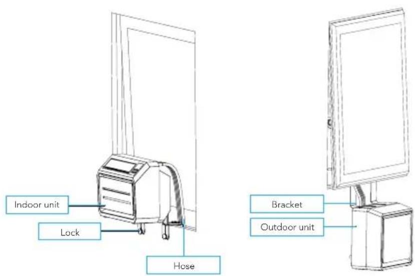
2.3 Install the complete unit in the caravan window and tighten the bracket properly (see figure).
text_image
Indoor unit Lock Hose Bracket Outdoor unit7. Operation manual
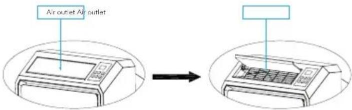
Open the air outlet
Turn the air outlet upwards manually so that it is fully opened (see picture).
text_image
Air outlet Air outletActivate air conditioning
Plug it into the socket. If you hear a short beep and see that the control panel lights up and goes off immediately, it means that the machine is activated.
To turn on
Press the "ON / OFF button to turn on the machine. If you hear two short beeps and the temperature is digitally displayed on the air conditioner, the air conditioner is switched on. When the air conditioner is switched on, the temperature is set to 22 °C by default. The lights of "(M) medium wind speed" and "air conditioning" light up and the fan of the indoor unit turns on. The temperature sensor measures the ambient temperature and if it exceeds 22 °C, the outdoor unit starts to work to bring the temperature down. Is the ambient temperature already below 22 °C? Then the outdoor unit does not start.
Wind speed
When the "SPEED" is pressed, the machine may emit a short beep. This button allows you to set the indoor unit fan to "(L) Low wind speed", "(M) Medium wind speed" or "(H) High wind speed". The corresponding lights indicate which setting is selected.
Switching between A/C mode and fan mode
You can switch from A/C to fan mode by pushing the "MODE" button. The light next to "Fan" will switch on and the light next to "A/C" will switch off. The compressor and fan of the outside unit will switch off. Only the fan of the inside unit will stay on. This way, you can enjoy a refreshing breeze, without the cooling function. You can switch back to A/C mode by pushing the "MODE" button again.
Set the temperature
When you press the "UP" button, the machine will emit a short beep. The temperature is increased by 1°C each time. The highest possible temperature setting is 30°C. When you press the "DOWN" button, the machine will emit a short beep. The temperature is decreased by 1°C each time. The lowest possible temperature setting is 16°C.
Sleep mode
Press the "SLEEP" button to activate the sleep mode. After 6 seconds, all lights and the digital display turn off and the air conditioner goes to sleep. The indoor unit fan continues to run at low (L) wind speed. This way you will not be bothered by light and sound, and you can sleep peacefully. When you press any button on the control panel, the machine beeps briefly and returns to its original operating mode.
WI-FI connection
Insert the plug of the air conditioner into the power socket: the air conditioner is in standby mode, all touch buttons will light up. The Wi-Fi connection indicator light is flashing slowly for about 10 seconds (it is searching for the Wi-Fi). When the device is connecting to the Wi-Fi, the light is flashing quickly (3x per second). After the Wi-Fi connection is complete, the Wi-Fi light will be on without flashing, indicating that the Wi-Fi is connected properly.
To make a new Wi-Fi connection, press the fan button for 3 seconds until you hear a 'beep' to exit the Wi-Fi mode. Press the fan button again for 3 seconds, until you hear a 'beep', to start the Wi-Fi mode again.
Follow the steps under 'Connecting the device to the app' to connect the device to your phone.
Switch off
Press the "ON / OFF" button to turn off the air conditioner. The machine beeps long and all lights turn off. The machine stops working and goes into standby mode until the machine is switched on again.
8. Connecting the device to the app
Installing the app
- Download the free Tuya Smart app from the Apple App Store or the Google Play Store.
- Create an account or log in. Enter a valid email address to receive the verification code.
Connecting the device to the app
-
Insert the plug of the air conditioner into the power socket, make sure that you have Wi-Fi connection and Bluetooth on. The air conditioner is in standby mode, all touch buttons will light up.
-
Open the app, log in and press the 'Add device' button.
-
Select "big home appliance", select "air conditioner(Bluetooth+Wi-Fi)" and accept the location services if necessary.
-
Check if the Wi-Fi light on the device is flashing quickly (3x per second). If the light is flashing slowly, fan button for 3 seconds until you hear a 'beep' to exit the Wi-Fi mode. Press the fan button again for 3 seconds, until you hear a 'beep', to start the Wi-Fi mode again.
-
Confirm in the app that the light is flashing quickly.
-
Select the Wi-Fi network to which you are normally connected and enter your Wi-Fi password*.
-
Click 'next' to pair the air conditioner with the app.
* Please note: You can only connect to the device via a 2.4 GHz Wi-Fi connection.
App functions
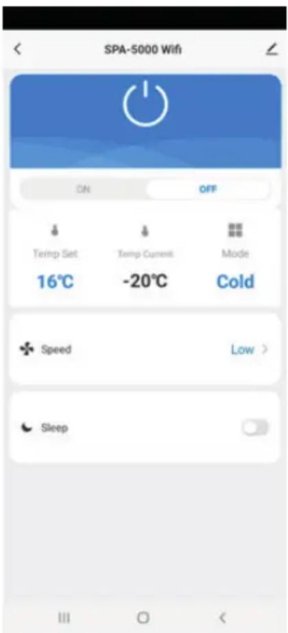
text_image
SPA-5000 Wifi ON OFF Temp Set Temp Current Mode 16°C -20°C Cold Speed Low > SleepIf both your smartphone and the air conditioner are connected to the internet, you can connect to the device from anywhere.
- Power (on/off): You can use the power function to switch the device on or off, no matter where you are.
- Temperature settings: You can set the temperature from 16 °C to 30 °C.
- Current temperature: You can check the current ambient temperature.
- Operating mode: You can change the mode to cooling or ventilating.
- Fan speed: You can change the fan speed to low, middle or high.
- Sleep mode: This function ensures that the device makes as little noise as possible.
9. Error code list
If the device does not work or works insufficiently:
Check if an error code is visible in the display, refer to the error code table for a solution. If no error code is visible in the display, go through the error table for a possible solution.
| Error codes | ||
| Error code Cause Solution | ||
| E1 Room temperature sensor fault Contact the dealer | ||
| E2 System temperature sensor fault | ||
| E4 Insufficient refrigerant | ||
| E5 Fan failure | ||
| E6 Condensation pump malfunction | ||
10. Failure guide
| Failure guide | ||
| Problem Cause Solution | ||
| The device does not turn on No power Turn | power on | |
| Damaged electrical outlet Turn off the power and check / repair the power outlet | ||
| Unknown reason Contact the dealer | ||
| Little air displacement or limited cooling effect | The lowest ventilation setting is selected Select the medium or high ventilation speed modus | |
| The air filter is dirty Check and clean the filter | ||
| The air supply or exhaust of the indoor unit is blocked | Check that the unit is not blocked and remove the obstruction | |
| The air supply or exhaust from the outdoor unit is blocked | Check that the unit is not blocked and remove the obstruction | |
| The ambient temperature is too low or high The ambient temperature must be between 16 and 40 °C | ||
| Insufficient voltage from the power supply Consult an installer or use a different power connection | ||
| Air displacement only but no cooling effect | The device runs in ventilation mode Select the cooling mode (A / C) | |
| The cooling mode has just turned off automatically | Wait about 3-5 minutes until the thermostat switches on again | |
| Abnormal sounds or vibrations | The mounting brackets are not properly installed on the vehicle, or the device mounting screws are not sufficiently tightened | Check that the mounting bracket is tight and tighten the device mounting screws |
| Water is leaking from the indoor unit | The rubber stopper on the bottom of the indoor unit is missing, or is not pressed enough | Check or replace the plug |
| The device is at an angle | The device must be mounted horizontally (maximum angle <3 °) | |
| The appliance emits a related odor | There is a serious problem | Switch off the device immediately and contact the dealer |
11. Maintenance
To clean
Caution: Unplug the power cord before cleaning the product.
For cleaning the outside:
Wipe the outside with a damp cloth. Then dry the device thoroughly with a dry cloth. Do not allow water or detergent to enter the machine. Do not clean the air conditioner with an aggressive cleaning agent and / or petrol.
Clean filter:
It is important to regularly remove the dust from the filter. Remove the filter as shown in the picture below. Clean the filter with tap water and / or a vacuum cleaner to remove any dirt from the filter. Make sure the filter has dried before putting it back in the air conditioner. Do not use water hotter than 40 °C for cleaning and do not expose the filter to the sun.
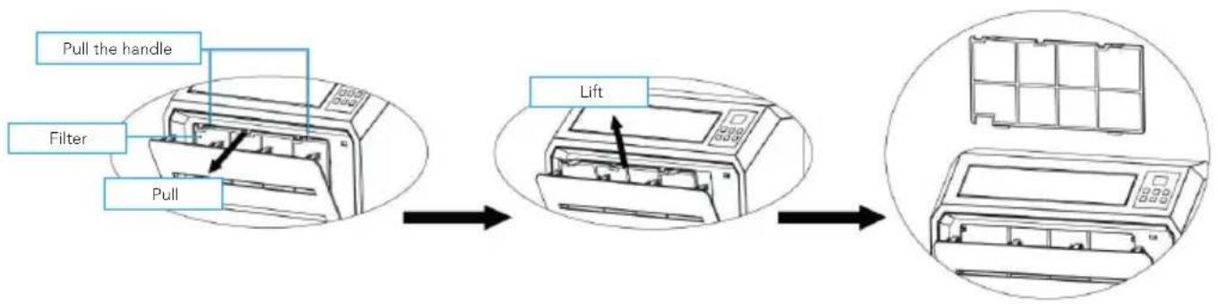
flowchart
graph LR
    A["Pull the handle"] --> B["Filter"]
    B --> C["Pull"]
    C --> D["Lift"]
    D --> E["Final air conditioner unit with grid box"]
Maintenance
Remove the rubber seal from the condensation drain and drain the condensation moisture in an appropriate place when you store the air conditioner for a longer period of time. Then replace the "rubber seal.
Clean the air conditioner according to the guidelines under "cleaning".
Store the air conditioner in a cool and dry place. We recommend that you put the air conditioner back in its packaging when you store it. This prevents dirt and dust from collecting on the air conditioner.
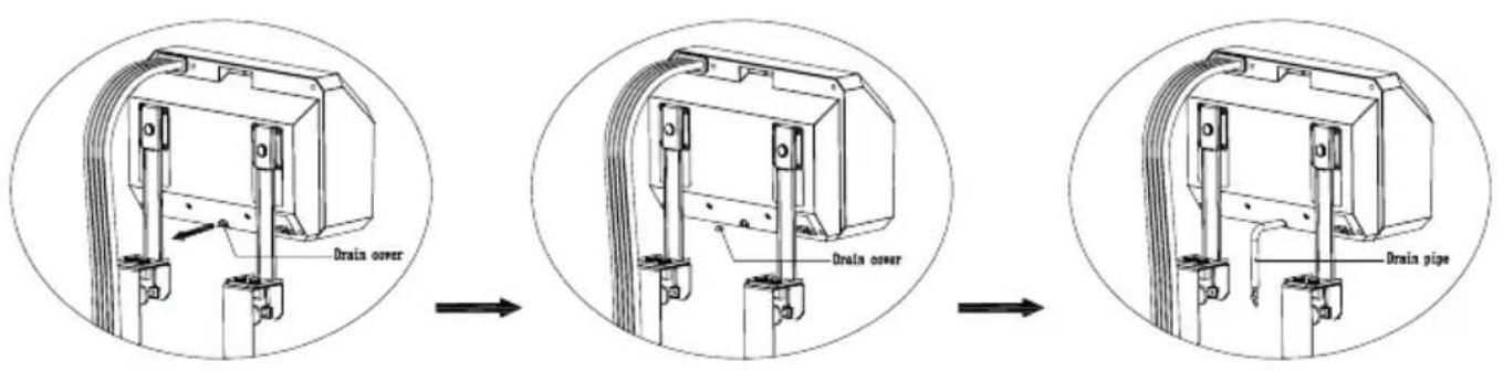
text_image
Drain cover Drain cover Drain pipeStorage & transport
You can easily transport the air conditioner and store it compactly. Use the hand screws to install the carrying bracket to the indoor unit, as shown in the picture.
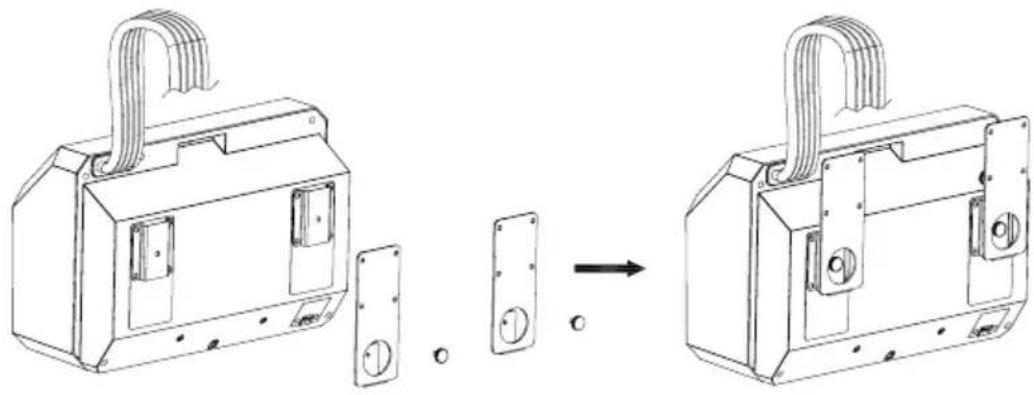
natural_image
Technical line drawing of a mechanical device with two components and a close-up view of its internal structure (no text or symbols)Use the hand screws to install the carrying bracket to the outdoor unit as shown in the picture. This way you create a compact whole that you can easily transport and store. Store the air conditioner in a cool, dry place.
text_image
mestic mestic
Correct disposal of this product.
This symbol means that this product should not be disposed of with normal household waste (2012/19 / EU). Recycle responsibly to promote sustainable reuse of material resources and to prevent potential damage to the environment or human health. Do you want to return the used device? Read the warranty conditions of where the product was purchased. Here you can return the product for environmentally safe recycling.
Declaration of conformity
Gimeg Nederland B.V. hereby declares that the device SPA-5000 complies with the basic requirements and other relevant regulations that fall under the European directive standard EU206-2012.
EN 60335-1:2012+A11+A13+A1+A2+A14
EN 60335-2-40:2003+A11+A12+A1+A2+A13 EN 62233: 2008
EN 55014-1:2017
EN 55014-2:2015
EN 61000-3-3:2013+A1
EN IEC 61000-3-2 2019
You can request a full declaration of conformity from the address shown on the back.
Inhaltsverzeichnis
text_image
ACN1 MAIN BOARD ACN3 FAN ACL COMP. CN2 WATER2 PT RT coil sensor room sensor LED DISPLAY water pump blue Brown Blue GN/YW L N E Blue Red Black Yellow White Fan Motor Terminal Board L C N Red Brown White Fan Motor GN/YW Blue Red C Black S COMP. R Blue GN/YW Water Level Sensor4. Packliste
natural_image
Diagram showing a mechanical assembly before and after transformation, with no visible text or symbolstext_image
Technical diagram showing three-step assembly of a mechanical bracket with labeled parts and cross-sectional viewstext_image
Drain power Drain power Drain pipenatural_image
Technical line drawing of a mechanical housing assembly showing part assembly before and after (no text or symbols)text_image
ACN1 MAIN BOARD ACN3 FAN ACL COMP. CN2 WATER2 PT RT coil sensor room sensor LED DISPLAY water pump blue Brown Blue GN/YW L N E Blue Red Black Yellow White Fan Motor Terminal Board L C N Red Brown White Fan Motor GN/YW Blue Red C Black S COMP. R Blue GN/YW Water Level Sensornatural_image
Diagram showing a mechanical assembly before and after transformation, with no visible text or symbolstext_image
Technical diagram showing a mechanical assembly with three stages: step, cross-section, and final detail view.text_image
Drain power Drain power Drain pipenatural_image
Technical line drawing of a mechanical housing assembly showing part assembly before and after (no text or symbols)text_image
ACN1 MAIN BOARD ACN3 FAN ACL COMP. CN2 WATER2 PT RT coil sensor room sensor LED DISPLAY water pump blue ~220V-240V50/60Hz Brown Blue GN/YW L N E Blue Red Black Yellow White Fan Motor Terminal Board L C N Red Brown White Fan Motor GN/YW Blue Red C Black S COMP. R Blue GN/YW4. Lista de envío
natural_image
Diagram showing a mechanical assembly before and after transformation, with no visible text or symbolstext_image
Technical diagram showing three-step assembly of a mechanical bracket with labeled parts and cross-sectional viewstext_image
Drain power Drain power Drain pipenatural_image
Technical line drawing of a door lock assembly showing part assembly and mounting (no text or symbols)text_image
ACN1 MAIN BOARD ACN3 FAN ACL COMP. CN2 WATER2 PT RT coil sensor room sensor LED DISPLAY water pump blue Brown Blue GN/YW L N E Blue Red Black Yellow White Fan Motor Terminal Board L C N Red Brown White Fan Motor GN/YW Blue Red C Black S COMP. R Blue GN/YW Water Level Sensornatural_image
Diagram showing a mechanical assembly before and after transformation, with no visible text or symbolstext_image
Technical diagram showing a mechanical assembly with three stages: step, cross-section, and final detail view.text_image
Drain power Drain power Drain pipenatural_image
Technical line drawing of a door lock assembly showing part assembly and mounting (no text or symbols)text_image
ACN1 MAIN BOARD ACN3 FAN ACL COMP. CN2 WATER2 PT RT coil sensor room sensor LED DISPLAY water pump water Level Sensor blue Brown Blue GN/YW L N E Blue Red Black Yellow White Fan Motor Terminal Board L C N Red Brown White Fan Motor GN/YW Blue Red C Black S COMP. R Blue Blue GN/YW4. Pakkeliste
natural_image
Diagram showing a mechanical device before and after assembly, with no visible text or symbolstext_image
Technical diagram showing mechanical assembly steps with labeled components and cross-sectional viewstext_image
Drain cover Drain cover Drain pipenatural_image
Technical line drawing of a mechanical device with two components and a close-up view of its internal structure (no text or symbols)text_image
ACN1 MAIN BOARD ACN3 FAN ACL COMP. CN2 WATER2 PT RT coil sensor room sensor LED DISPLAY water pump blue Brown Blue GN/YW L N E Blue Red Black Yellow White Fan Motor Terminal Board L C N Red Brown White Fan Motor GN/YW Blue Red C Black S COMP. R Blue GN/YW4. Leveranslista
natural_image
Diagram showing a mechanical assembly before and after transformation, with no visible text or symbols.text_image
Technical diagram showing a mechanical assembly with three stages: step, cross-section, and final detail view.text_image
Drain cover Drain power Drain pipenatural_image
Technical line drawing of a mechanical device with two components and a close-up view of its internal structure (no text or symbols)text_image
ACN1 MAIN BOARD ACN3 FAN ACL COMP. CN2 WATER2 PT RT coil sensor room sensor LED DISPLAY water pump blue Brown Blue GN/YW L N E Blue Red Black Yellow White Fan Motor Terminal Board L C N Red Brown White Fan Motor GN/YW Blue Red C Black S COMP. R Blue GN/YW Water Level Sensor4. Pakkeliste
| Navn QTY | |
| Indre enhet 1 | |
| Ytre enhet 1 | |
| Avløpsslange 1 | |
| Utvendig brakett 2 | |
| Innvendig brakett 2 | |
| Oppbevaringsbrakett 2 | |
| Støtabsorberende gummiblokker 2 | |
| Støtteblokker 2 | |
| Håndskruer 14 | |
| Vridningslås 2 | |
| Hulmutter 2 | |
| Brukerhändbok 1 |
5. Deler