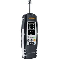
MultiWetFinder Plus - Measuring equipment Laserliner - Free user manual and instructions
Find the device manual for free MultiWetFinder Plus Laserliner in PDF.



| Product type | Moisture measurement equipment (capacitive) |
| Brand | Laserliner |
| Model | MultiWetFinder Plus |
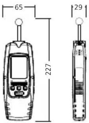
| Dimensions (W x H x D) | 65 mm x 227 mm x 29 mm |
| Weight (including batteries) | 228 g |
| Power supply | 3 x 1.5 V LR03 (AAA) alkaline batteries |
| Battery life | Approximately 55 hours |
| Measurement modes | Index mode (material-independent) and Building Materials mode (cement screed, anhydrite screed, concrete) |
| Main functions | Capacitive moisture measurement, hygrometer (temperature, relative humidity, dew point), LED display dry/damp/wet (12 bars), audible alarm, REF function, MAX function, automatic calibration, adjustable auto-off (3 or 60 min), digital connection IEEE 802.15.4 (max range 10 m) |
| Measurement range (ambient temperature) | -10 °C to 60 °C |
| Measurement range (relative humidity) | 20 % to 90 % RH |
| Accuracy (ambient temperature) | ± 1 °C |
| Accuracy (relative humidity) | 20 % to 80 %: ± 3 %; <20 % or >80 %: ± 5 % |
| Resolution | Temperature: 0.1 °C; relative humidity: 0.1 %; dew point: 0.1 °C |
| Operating conditions | 0 °C to 50 °C, max. 85 % RH (non-condensing), max. altitude 2000 m |
| Storage conditions | -10 °C to 60 °C, max. 85 % RH (non-condensing) |
| Maintenance and cleaning | Clean with a slightly damp cloth; avoid aggressive cleaning agents, solvents, and abrasives. Remove batteries if storing for an extended period. Store in a dry and clean place. |
| Calibration | Recommended once a year; contact UMAREX-LASERLINER customer service |
| Safety | Use in accordance with specifications. Do not modify the device. Do not use with external voltage. Follow RF regulations (RED 2014/53/EU). Keep out of reach of children. |
| Repairability and spare parts | Contact UMAREX-LASERLINER after-sales service for any repairs or calibration. |
| General information | Compliant with EU and UK standards. Recycling according to WEEE directives. Full manual available at notice-facile.com |
Frequently Asked Questions - MultiWetFinder Plus Laserliner
User questions about MultiWetFinder Plus Laserliner
0 question about this device. Answer the ones you know or ask your own.
Ask a new question about this device
Download the instructions for your Measuring equipment in PDF format for free! Find your manual MultiWetFinder Plus - Laserliner and take your electronic device back in hand. On this page are published all the documents necessary for the use of your device. MultiWetFinder Plus by Laserliner.
USER MANUAL MultiWetFinder Plus Laserliner

DIGITAL CONNECTION
Laserliner
!
natural_image
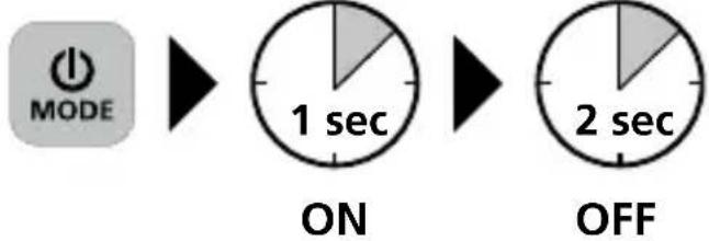
Diagram of a mobile phone's internal structure showing a device with a black arrow indicating a directional change (no text or symbols present)2 ON / OFF
flowchart
graph TD
    A["MODE"] --> B["MENU"]
    B --> C["REF"]
    B --> D["MAX SET"]
    C --> E["FIND"]
    D --> E
    style A fill:#000,stroke:#fff,color:#fff
    style B fill:#000,stroke:#fff,color:#fff
    style C fill:#000,stroke:#fff,color:#fff
    style D fill:#000,stroke:#fff,color:#fff
    style E fill:#000,stroke:#fff,color:#fff
1 ON/OFF
Umschaltung Index-,
Baumaterial-Modus;
Auswahl bestätigen
2 Messen
3 Einstellungsmenü
4 MAX-Funktion;
8...12 LEDs rot = nass
natural_image
Pure mechanical component diagram without any text, numbers, or symbolshttps://packd.li/ble/v2

!
Completely read through the operating instructions, the "Warranty and Additional Information" booklet as well as the latest information under the internet link at the end of these instructions. Follow the instructions they contain. This document must be kept in a safe place and if the laser device is passed on, this document must be passed on with it.
Intended use
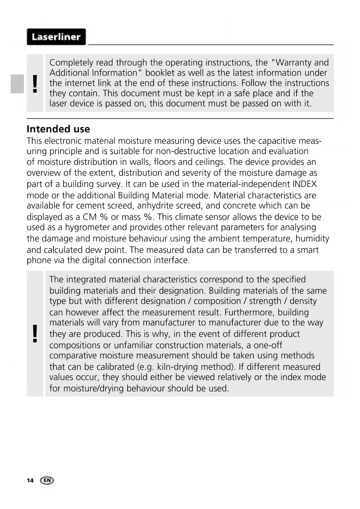
This electronic material moisture measuring device uses the capacitive measuring principle and is suitable for non-destructive location and evaluation of moisture distribution in walls, floors and ceilings. The device provides an overview of the extent, distribution and severity of the moisture damage as part of a building survey. It can be used in the material-independent INDEX mode or the additional Building Material mode. Material characteristics are available for cement screed, anhydrite screed, and concrete which can be displayed as a CM % or mass %. This climate sensor allows the device to be used as a hygrometer and provides other relevant parameters for analysing the damage and moisture behaviour using the ambient temperature, humidity and calculated dew point. The measured data can be transferred to a smart phone via the digital connection interface.
!
The integrated material characteristics correspond to the specified building materials and their designation. Building materials of the same type but with different designation / composition / strength / density can however affect the measurement result. Furthermore, building materials will vary from manufacturer to manufacturer due to the way they are produced. This is why, in the event of different product compositions or unfamiliar construction materials, a one-off comparative moisture measurement should be taken using methods that can be calibrated (e.g. kiln-drying method). If different measured values occur, they should either be viewed relatively or the index mode for moisture/drying behaviour should be used.
!
The operating principle of the device can only determine the material moisture measurement in % and show the moisture content on the LED display when the material matches the specified internal material characteristics.
General safety instructions
- The device must only be used in accordance with its intended purpose and within the scope of the specifications.
- The measuring tools and accessories are not toys. Keep out of reach of children.
- Modifications or changes to the device are not permitted, this will otherwise invalidate the approval and safety specifications.
- Do not expose the device to mechanical stress, extreme temperatures, moisture or significant vibration.
- The device must no longer be used if one or more of its functions fail or the battery charge is weak.
- The measuring ball head must not be operated under external voltage.
- Please ensure compliance with the safety regulations set out by local and national authorities with regard to the correct and proper use of the device.
Safety instructions
Dealing with RF radiation
- The measuring device is equipped with a wireless interface. The measuring device complies with electromagnetic compatibility and wireless radiation regulations and limits in accordance with the RED 2014/53/EU.
- Umarex GmbH & Co. KG hereby declares that the MultiWet-Finder Plus radio equipment complies with the essential requirements and other provisions of the European Radio Equipment Directive 2014/53/EU (RED).
The EU Declaration of Conformity can be found in its entirety at the following address: https://packd.li/ll/akx/ce
Laserliner
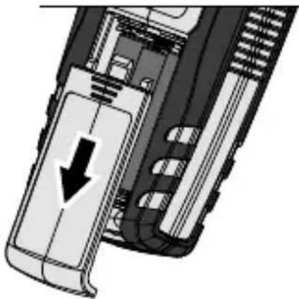
1 Inserting and removing the batteries
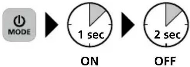
Open the battery compartment on the rear of the housing and insert 3 x 1.5V LR03 (AAA). Correct polarity must be observed. Replace the battery compartment cover. The device can now be switched on. The device must be switched off before removing the batteries.
natural_image
Diagram of a device's internal structure showing a directional arrow and component layout (no text or symbols)2 ON / OFF
flowchart
graph TD
    A["MODE"] --> B["MENU"]
    B --> C["REF"]
    B --> D["MAX SET"]
    C --> E["FIND"]
    D --> E
    style A fill:#000,stroke:#fff,color:#fff
    style B fill:#000,stroke:#fff,color:#fff
    style C fill:#000,stroke:#fff,color:#fff
    style D fill:#000,stroke:#fff,color:#fff
    style E fill:#000,stroke:#fff,color:#fff
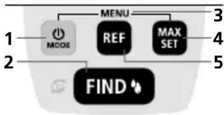
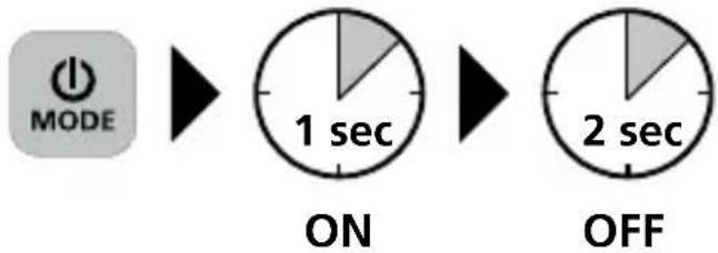
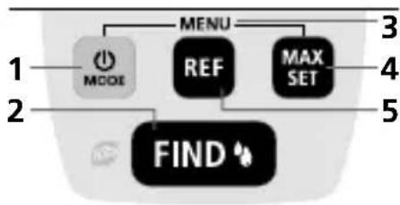
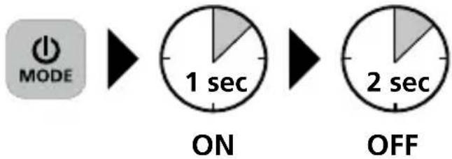
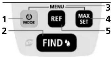
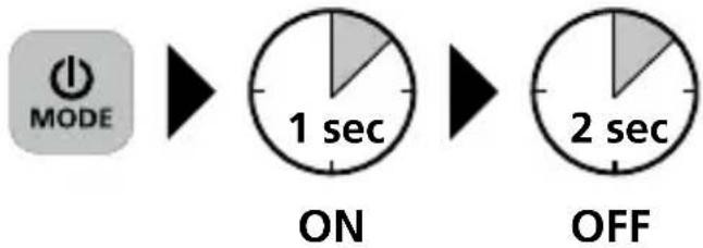
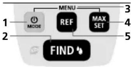
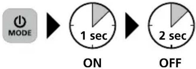
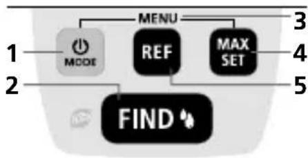
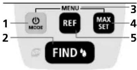
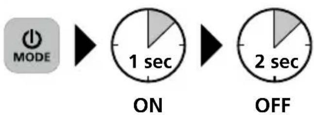
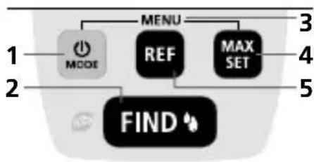
1 ON/OFF Switchover index-, building material mode; confirm selection
2 Measuring
3 Settings menu
4 MAX function; Select material group
5 REF function
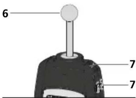
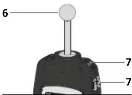
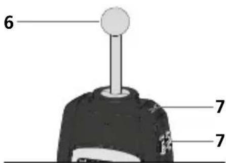
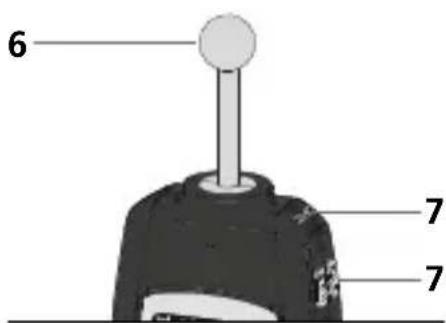
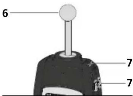
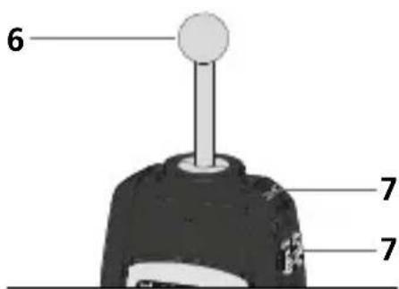
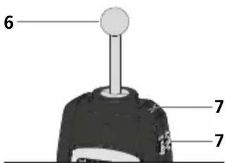
6 Spherical measuring head
7 Climate sensor
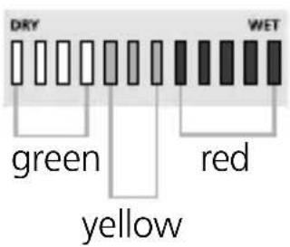
Wet/dry LED display
12-position LED:
0...4 LEDs green = dry
5...7 LEDs yellow = moist
8...12 LEDs red = wet
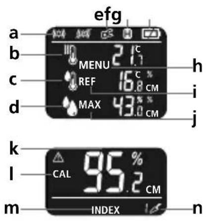
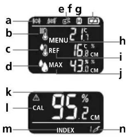
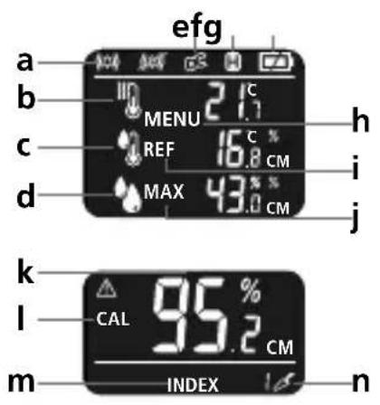
a Acoustic alarm on/off
b Ambient temperature
c Dew point temperature
d Humidity
e Digital connection active
f AutoHold
g Battery charge
h Menu mode active
i Reference value
j Maximum measured value
k relative material moisture
I Calibration
m Index mode selected
n Building material mode selected
3 Select mode
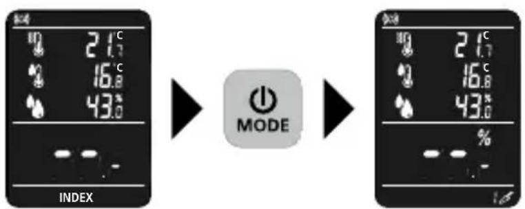
The device features 2 modes for measuring moisture, depending on the material in question. Press the 'MODE' button to change between the central, material-independent INDEX mode and the additional Building Material mode.
4 Wet/dry LED display
In addition to the numerical display of the measured value in % relative material moisture, the LED display provides an additional visual evaluation of the moisture. Fixed material characteristics are stored for cement screed, anhydrite screed and concrete. In INDEX mode, you can set an individual threshold value. The LED display bar becomes larger, from left to right, with increasing moisture content. The 12-position LED display is subdivided into 4 green (dry), 3 yellow (moist) and 5 red (wet) segments. Wet material causes an additional acoustic signal.

The classification "dry" means that materials in a heated room have reached a balanced moisture level and are thus suitable for further processing.
5 Selecting the material
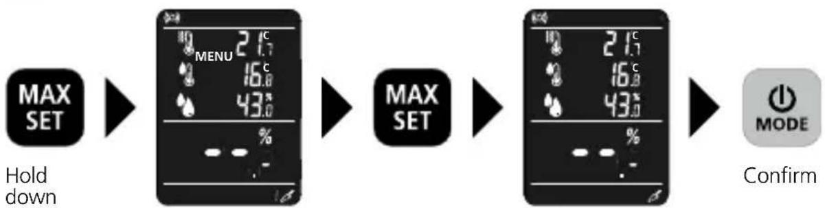
flowchart
graph LR
    A["MAX SET"] --> B["MENU 21.7℃"]
    B --> C["MAX SET"]
    C --> D["MODE 21.7℃"]
    D --> E["Confirm"]
There are three material groups: cement screed, anhydrite screed, and concrete in CM % or mass % The most recently used material is retained with each restart.
Material groups
| Cement screed Mass % | |
| Anhydrite screed Mass % | |
| Concrete Mass % | |
| Cement screed CM % | |
| Anhydrite screed CM % | |
| Concrete Mass % |
6 Index mode
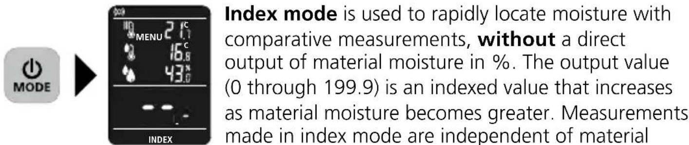
type and particularly useful with materials for which no characteristics are stored. When comparative measurements reveal strongly deviating values, the course of moisture in the material can be localized quickly.
7 Measuring process
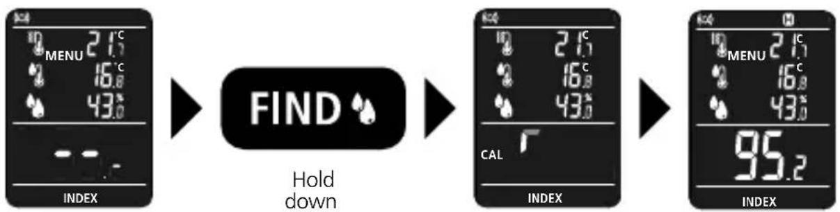
flowchart
graph LR
    A["INPUT: MENU 21.7°C, 16.8°C, 43.0°C"] --> B["FIND: HOLD down"]
    B --> C["OUTPUT: 21.7°C, 16.8°C, 43.0°C, CAL"]
    C --> D["OUTPUT: 21.7°C, 16.8°C, 43.0°C, 95.2°C"]
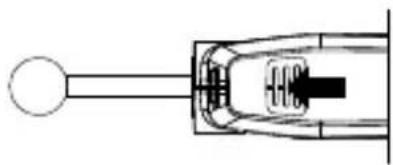
The device starts automatically in Index mode and does not always need to be calibrated to zero in mid-air to compensate environmental influences. The spherical measuring head must not be in contact with the user's hands or other objects during calibration. For zero calibration, hold down the 'FIND' button and hold the device in a free space. Continue to hold the 'FIND' button down after the beep and position the spherical measuring head perpendicular to the item to be measured. Once the measured value appears in the display, release the 'FIND' button. The measured value is retained automatically.
8 Information on use
- Contamination should be removed from the measurement location before measuring.
- The device requires approx. 15 minutes to acclimatise to the ambient temperature, depending on the location.
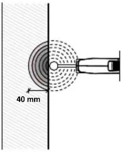
- Always hold the spherical measuring head against the item to be measured with a constant pressure.
- Do not tilt the device during the measuring process, do not slide it along the item to be measured, and do not lean on the device.
- The raw density of the item to be measured has a considerable influence on the result of the measurement; the higher it is, the higher the measured value determined.
– Rough surfaces lead to a lower measured value being displayed.
- If the sensor detects metal (e.g. pipes, screws, wiring) in the item to be measured, this results in a significantly higher measured value which cannot be used.
- When positioning the spherical measuring head in corners, a higher measured value is displayed than on flat surfaces as the spherical measuring head is in contact with more material. A distance of 10 ~cm must be maintained from corners.
- The percentage measured values in material mode are trends and do not replace, for example, precise checking of the readiness of screed for covering.
- To ensure correct measurements are taken, the climate sensor must not be covered by the hand.
natural_image
Pure mechanical component diagram without any text, numbers, or symbols9 REF function
flowchart
graph LR
    A["2.1°C MENU"] --> B["REF"]
    B --> C["38.8% MAX"]
    C --> D["FIND"]
    D --> E["38.8% MAX"]
    E --> F["54.0% INDEX"]
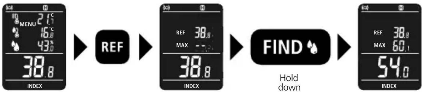
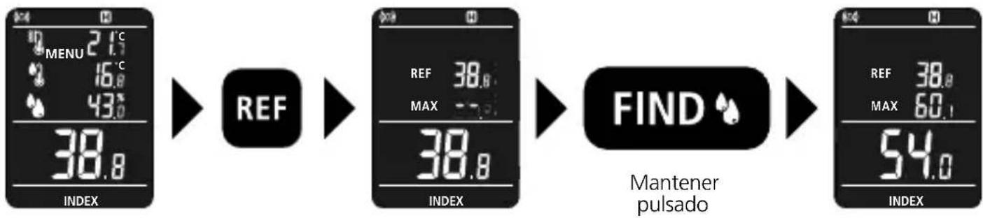
The Reference function allows you to gain an overview of the moisture distribution in the wall. Find a dry point on the item to be measured and determine the moisture content as described in section 6 “Measuring process”. Fix the measured value as a reference value by pressing the ‘REF’ button. Then complete a moisture measurement elsewhere. This gives you an overview from the reference value, maximum measured value and current measured value.
10 MAX function
flowchart
graph LR
    A["MENU 2.1°C"] --> B["MAX SET"]
    B --> C["MAX"]
    C --> D["FIND"]
    D --> E["MAX 95.2"]
    style A fill:#f9f,stroke:#333
    style B fill:#ccf,stroke:#333
    style C fill:#cfc,stroke:#333
    style D fill:#fcc,stroke:#333
    style E fill:#cff,stroke:#333
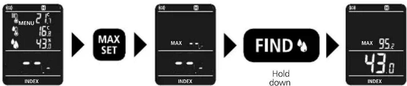
The device can only retain a MAX value as part of a measuring process. The MAX value is displayed after the measuring process. The MAX value and the current value are displayed by holding down the 'FIND' button during a new measurement.
11.0 Settings menu
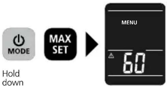
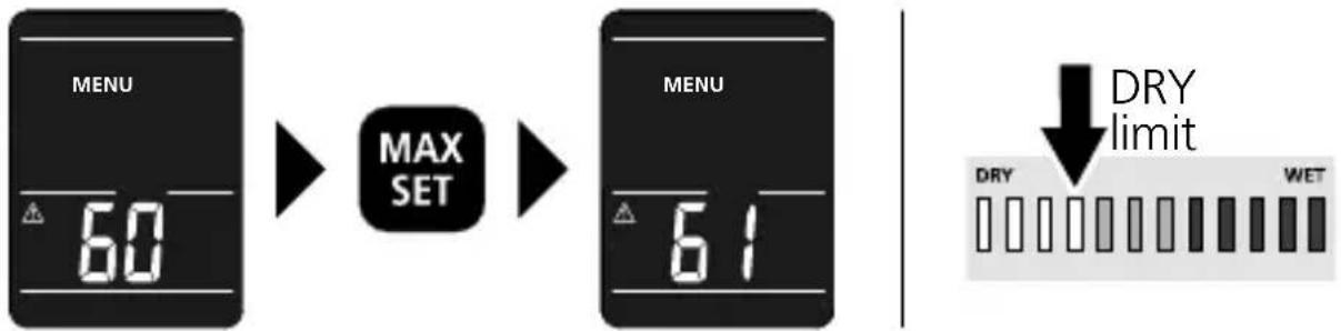
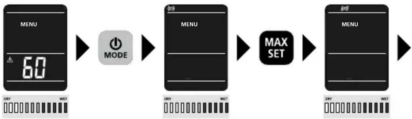
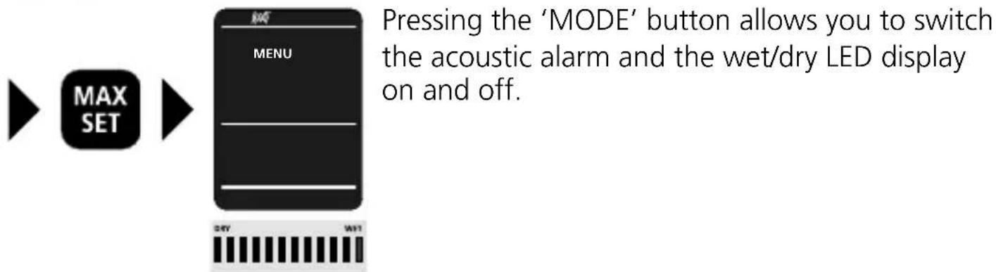
Holding down the ON/OFF button and the MAX button at the same time takes you to the menu. The dry limit value, alarm and automatic power off can be set from here.
11.1 Setting the dry limit
flowchart
graph LR
    A["MENU 60"] --> B["MAX SET"]
    B --> C["MENU 61"]
    D["DRY"] --> E["DRY limit"]
    F["WET"] --> G["WET"]
The wet/dry LED indicator is programmed in line with the relevant material characteristics so the LEDs also provide information about whether the material should be classified as dry, moist or wet. Holding down the 'MODE' button and the 'MAX SET' button at the same time takes you to the menu. Pressing the 'MAX SET' button allows you to set the dry limit only in INDEX mode. This limit value must be established away from the specific point of use. As soon as Building material mode is selected, the LED display appears based on the saved material parameters.
11.2 Alarm / LED display
flowchart
graph LR
    A["MENU 60°"] --> B["MODE"]
    B --> C["DNY WET"]
    C --> D["MAX SET"]
    D --> E["DNY WET"]
11.3 Auto shut-off
flowchart
graph LR
    A["MENU\n60"] --> B["MODE"]
    B --> C["MENU\n60"]
    C --> D["MAX SET"]
    D --> E["MENU\nP OF"]
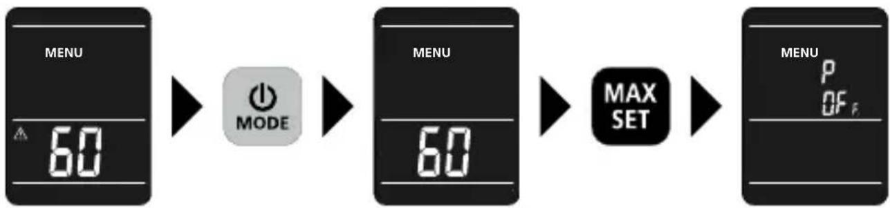
The device has an automatic power off. This can be set for 3 or 60 minutes. When using the device as a hygrometer to monitor an indoor climate, it makes sense to set the automatic power off to 60 minutes.
Data transfer
This device has digital connectivity which allows wireless data transfer to mobile devices such as smart phones or tablets with a wireless interface.
The system prerequisites for a digital connection are specified at https://packd.li/ble/v2
This device can generate a wireless connection to devices which are compatible with the wireless standard IEEE 802.15.4. The wireless standard IEEE 802.15.4 is a transfer protocol for Wireless Personal Area Networks (WPAN). The range is set to a maximum distance of 10m from the terminal device and greatly depends on the ambient conditions such as the thickness and composition of walls, sources of interference as well as the transmit / receive properties of the terminal device.
Application (app)
An app is required to use the digital connection You can download the app from the corresponding stores for the specific type of terminal device:



Make sure that the wireless interface of the mobile device is activated.
After starting the app and activating the digital connection, a connection can be set up between a mobile device and the measuring device. If the app detects several active measuring devices, select the matching device. This measuring device can be connected automatically the next time it is switched on.
Information on maintenance and care
Clean all components with a damp cloth and do not use cleaning agents, scouring agents and solvents. Remove the battery(ies) before storing for longer periods. Store the device in a clean and dry place.
Calibration
The measuring device must be calibrated and tested on a regular basis to ensure it is accurate and working properly. We recommend carrying out calibration once a year. Contact your distributor or the UMAREX-LASERLINER service department.
Technical data (Subject to technical changes without notice. 22W50)
| Measured variables | Moisture content of material (capacitive)HumidityAmbient temperatureDew point temperature |
| Mode | IndexBuilding materialsReference |
| Functions | Automatic shutdownHOLDMAX |
| Measurement range | Ambient temperature: -10°C ... 60°CHumidity (relative): 20% ... 90% |
| Accuracy | Ambient temperature: ± 1°CHumidity (absolute): 20% ... 80% (± 3%)Humidity (relative): <20% and >80% (± 5%) |
| Resolution | Ambient temperature: 0.1°CLuftfeuchte (relativ): 0.1%Dew point temperature: 0.1°C |
| Automatic switch-off | ja |
| Power supply | 3 x 1.5V LR03 (AAA) |
| Chemical system | Alkaline |
| Operating time | approx. 55 hours |
| Operating conditions | 0°C ... 50°C, max. humidity 20 ... 85% rH,no condensation, max. working altitude 2000 m above sea level |
| Storage conditions | -10°C ... 60°C, max. humidity 85% rH,no condensation |
| Radio module operating data | IEEE 802.15.4. LE ≥ 5.x (Digital Connection) interface;Frequency band: ISM band 2400–2483.5 MHz,40 channels; Transmit power: max. 0.8 mW;Bandwidth: 1.5 MHz; Bit rate: 1 Mbit/s;Modulation: GFSK |
| Unit of measurement | % rM (relative material moisture)°C (Celsius)% rH (relative humidity) |
| Dimensions (W x H x D) | 65 mm x 227 mm x 29 mm |
| Weight | 228 g (incl. batteries) |
EU and UK directives and disposal
This device complies with all necessary standards for the free movement of goods within the EU and the UK.
This product, including accessories and packaging, is an electrical appliance that must be recycled in an environmentally appropriate manner in accordance with European and UK directives on waste electrical and electronic equipment, batteries and packaging, in order to recover valuable raw materials.
Further safety and supplementary notices at:
http://laserliner.com
!
natural_image
Cross-sectional diagram of a mobile phone showing internal components and a directional arrow (no text or symbols)2 ON / OFF
flowchart
graph TD
    A["1 MODE"] --> B["MENU"]
    B --> C["REF"]
    B --> D["MAX SET"]
    C --> E["3"]
    D --> F["4"]
    G["FIND"] --> H["5"]
12 leds:
0...4 leds groen = droog
5...7 leds geel = vochtig
8...12 leds rood = nat

natural_image
Pure mechanical component diagram without any text, numbers, or symbols
natural_image
Cross-sectional diagram of a mobile phone showing internal components and a directional arrow (no text or symbols)2 TÆND/SLUK (ON/OFF)
flowchart
graph TD
    A["MODE"] --> B["MENU"]
    B --> C["REF"]
    B --> D["MAX SET"]
    C --> E["FIND"]
    D --> E
    style A fill:#000,stroke:#000,color:#fff
    style B fill:#000,stroke:#000,color:#fff
    style C fill:#000,stroke:#000,color:#fff
    style D fill:#000,stroke:#000,color:#fff
    style E fill:#000,stroke:#000,color:#fff
natural_image
Pure mechanical component diagram without any text, numbers, or symbolshttps://packd.li/ble/v2



natural_image
Diagram of a device's internal structure showing a directional arrow and component layout (no text or symbols)2 MARCHE/ARRÊT
flowchart
graph TD
    A["1 MODE"] --> B["MENU"]
    B --> C["REF"]
    B --> D["MAX SET"]
    C --> E["3"]
    D --> F["4"]
    G["FIND"] --> H["5"]
natural_image
Pure mechanical component diagram without any text, numbers, or symbols9 Fonction REF
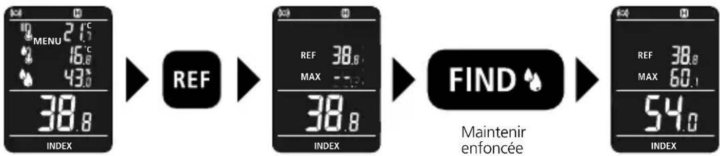
flowchart
graph LR
    A["Menu 2.1°C, 4.6°C, 43.0°C, 38.8°, INDEX"] --> B["REF"]
    B --> C["REF 38.8, MAX -7.2°, 38.8°, INDEX"]
    C --> D["FIND"]
    D --> E["REF 38.8, MAX 60.1°, 54.0°, INDEX"]
    style A fill:#f9f,stroke:#333
    style B fill:#ccf,stroke:#333
    style C fill:#cfc,stroke:#333
    style D fill:#fcc,stroke:#333
    style E fill:#cff,stroke:#333


natural_image
Cross-sectional diagram of a mobile phone showing internal components and a directional arrow (no text or symbols)2 ON / OFF
flowchart
graph TD
    A["1 MODE"] --> B["MENU"]
    B --> C["REF"]
    B --> D["MAX SET"]
    C --> E["3"]
    D --> F["4"]
    G["FIND"] --> H["5"]
natural_image
Pure mechanical component diagram without any text, numbers, or symbols9 Función REF
flowchart
graph LR
    A["38.8 INDEX"] --> B["REF"]
    B --> C["38.8 MAX"]
    C --> D["FIND"]
    D --> E["54.0 INDEX"]
    style A fill:#f9f,stroke:#333
    style B fill:#ccf,stroke:#333
    style C fill:#cfc,stroke:#333
    style D fill:#fcc,stroke:#333
    style E fill:#cff,stroke:#333
https://packd.li/ble/v2

Laserliner
!
natural_image
Cross-sectional diagram of a mobile phone showing internal components and a directional arrow (no text or symbols)2 ON / OFF
flowchart
graph TD
    A["MODE"] --> B["MENU"]
    B --> C["REF"]
    B --> D["MAX SET"]
    C --> E["FIND"]
    D --> E
flowchart
graph LR
    A["INPUT: MENU 21.7, 16.8, 43.0"] --> B["FIND"]
    B --> C["OUTPUT: 21.7, 16.8, 43.0, CAL"]
    C --> D["OUTPUT: 21.7, 16.8, 43.0, 95.2"]
natural_image
Pure mechanical component diagram without any text, numbers, or symbolshttps://packd.li/ble/v2

!
- ON / OFF
- https://packd.li/ble/v2
- Intended use
- !
- General safety instructions
- Safety instructions
- Laserliner
- Inserting and removing the batteries
- Wet/dry LED display
- Wet/dry LED display
- Selecting the material
- Index mode
- Measuring process
- Information on use
- REF function
- MAX function
- Settings menu
- Setting the dry limit
- Alarm / LED display
- Data transfer
- Application (app)
- Information on maintenance and care
- Calibration
- EU and UK directives and disposal
- TÆND/SLUK (ON/OFF)
- MARCHE/ARRÊT
- Fonction REF
- Función REF
Brand : Laserliner
Model : MultiWetFinder Plus
Category : Measuring equipment