75524001 - Smart Home BERKER - Free user manual and instructions
Find the device manual for free 75524001 BERKER in PDF.

User questions about 75524001 BERKER
0 question about this device. Answer the ones you know or ask your own.
Ask a new question about this device
Download the instructions for your Smart Home in PDF format for free! Find your manual 75524001 - BERKER and take your electronic device back in hand. On this page are published all the documents necessary for the use of your device. 75524001 by BERKER.
USER MANUAL 75524001 BERKER
text_image
(①) (A) U1 U1 U1 U1 SH2 A1 A2 A3 A4 SH3 B45 (B) A1 A2 A3 A4 (C) 230 V AC 24 V AC (D) (E)Anschluss

Operating Instructions
B.
Berker
instabus® KNX E13
4-channel analog actuator module
text_image
D GB NL F N EGB
Safety instructions
Attention!
- Electrical equipment must be installed and fitted only by qualified electricians and in strict observance of the applicable accident prevention regulations.
- Failure to observe any of the installation instructions may result in fire or other hazards.
- Do not connect electronic ballasts or electronic transformers with 1-10 V control input to the outputs.
- Do not connect external voltages to the outputs.
Connected components must ensure safe separation from other voltages.
- Do not connect the GND terminals with terminals of the same designation in the EIB device (risk of irreparable damage).
Function

- The analog actuator module enlarges an EIB analog actuator by four analog outputs which can be parameterized by means of software.
- Received data are converted into the following output signals: 0...1 V, 0...10 V, 0...20 mA or 4...20 mA.
- With these analog output signals, actuators used for heating, ventilation and air conditioning purposes are enabled to adapt their output variables in acc. with informations received from the bus and to be used within control processes.
- The output variables can be subject to forced control.
- The module data as such and the forced-control instructions are evaluated in the EIB analog actuator
GB
Function
- The analog actuator module is connected to the EIB device by means of a system connector supplied with the device.
• Non used outputs can be deactivated.
• Voltage outputs are monitored for short-circuits. - The output state is indicated by status LED.
Installation

The device is snap-fastened on a DIN rail 35 x 7,5 mm as per EN 50022.
The analog actuator module is connected to an EIB analog actuator only by means of a 6-pole system connector (supplied with the analog actuator module).
The analog actuator module needs an external 24 V power supply for operation, e.g order no. 7591 00 01.
This unit can also supply the connected the connected EIB analog actuator or other devices.
For easy connection, there are two pairs of internally connected power supply terminals (marked by a dot “•”).
text_image
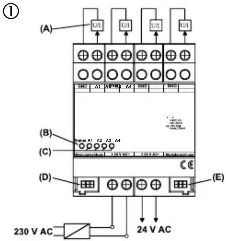
(①) (A) U1 U1 U1 U1 SH2 A1 A2 A3 A4 SH3 B45 (B) A1 A2 A3 A4 (C) 230 V AC 24 V AC (D) (E)Connection

GND : reference potential for outputs A1 ... A4
A1 ... A4 : analog outputs
24 V AC : external supply voltage
(A) : devices with analog interface
(B) : status LED of the analog actuator module, red
(C) : status LEDs of the four analog outputs, yellow
(D) : system connector, 6-pole, for module connection
(E) : system connector, 6-pole, for future extensions
Attention!
The GND terminals must not be connected with the terminals of the same designation of an analog actuator (risk of irreparable damage!).
GB
Connectable analog actuators

Safety warnings
- Do not connect electronic ballasts or electronic transformers with 1-10 V control input to the outputs.
- Do not connect external voltages to the outputs. Connected components must ensure safe separation from other voltages.
- Current outputs may be loaded with 500 max.
• Voltage outputs must be loaded with 1 kΩ min.
- The GND terminals of outputs A1...A4 are internally connected.
- In the event of a short-circuit between a voltage output A1 ... A4 and GND, the respective output is deactivated.
Installation of an analog actuator module

During the installation of an analog actuator module the following basic rules must be observed:
- An analog output module can be replaced (e.g. in case of defect) while the system is in operation (disconnect voltage supply from module!). After the replacement, the analog actuator makes a reset after abt. 25 s. This action re-initializes all outputs of the analog actuator and of the connected analog actuator module and resets them to their original state.
- Removal or addition of modules without adapting the project and subsequent downloading into the analog actuator is not permitted as this will result in system malfunctions.
GB
Status LED
Device status (red)
Commissioning of the module
On : Module ready for operation (self-test O.K).
Quickly blinking : Module initialization in progress
Slowly blinking : Module not configured (in EIB device)
Off : Module initialized and in operation
Precondition: LED must have been on beforehand!
Normal operation
On : Module not ready for operation (fault)
Off : Modul initialized and in operation.
Precondition: LED must have been on beforehand!
Slowly blinking = 1/s; quickly blinking = 2/s
Status LED

Output signals A1 ... A4 (yellow):
LED off : output signal is equal to zero LED on : output signal is greater than zero
GB
Technical Data
Power supply
Supply voltage : 24 V AC ± 10 %
Current consumption : 120 mA max.
Current consumption at
system connector : 6 mA
Ambient temperature : -5 °C ... +45 °C
Storage/transport temp. : -25 °C ... +70 °C
Humidity
Ambient/storage/transport : 93 % r.h. max., no condensation
Protective system : IP 20 as per EN 60529
Installation width : 4 modules / 72 mm
Weight : approx. 155 g
Connections
Outputs, power supply : screw terminals
single-wire : 0.5 mm ^2 to 4 mm ^2
stranded wire (without ferrule) : 0.34 mm ^2 to 4 mm ^2
stranded wire (with ferrule) : 0.14 mm ^2 to 2.5 mm ^2
Connection with KNX/EIB device : 6-pole system connector
Analog outputs
Number : 4
Evaluable sensor signals : 0 ... 1 V DC, 0 ... 10 V DC, 0 ... 20 mA, 4 ... 20 mA
Voltage signal load : ≥ 1 k
Current signal load : < 500 Ω
Subject to technical modifications.
GB
Acceptance of guarantee
Our products are under guarantee within the scope of the statutory provisions.
Please return the unit postage paid to our central service department giving a brief description of the fault:
CE The CE-sign is a free trade sign addressed exclusively to the authorities and does not include any warranty of any properties.
text_image
(①) (A) U1 U1 U1 U1 SH2 A1 A2 A3 A4 SH3 B45 (B) A1 A2 A3 A4 (C) 230 V AC 24 V AC (D) (E)Aansluiting

text_image
(①) (A) U1 U1 U1 U1 SH2 A1 A2 A3 A4 SH3 B45 (B) A1 A2 A3 A4 (C) 230 V AC 24 V AC (D) (E)Connexion

text_image
(①) (A) U1 U1 U1 U1 SH2 A1 A2 A3 A4 SH3 B45 (B) A1 A2 A3 A4 (C) 230 V AC 24 V AC (D) (E)Tilkopling
N
text_image
(①) (A) U1 U1 U1 U1 SH2 A1 A2 A3 A4 SH3 B45 (B) A1 A2 A3 A4 (C) 230 V AC 24 V AC (D) (E)Conexión