2912 - Switch BERKER - Free user manual and instructions
Find the device manual for free 2912 BERKER in PDF.

| Product Type | Light Switch |
| Brand | Berker |
| Model | 2912 |
| Dimensions (H x W x D) | 86 x 86 x 36 mm |
| Weight | 110 g |
| Rated Voltage | 250 V AC |
| Rated Current | 10 A |
| Number of Gangs | 1 |
| Number of Ways | 1-way |
| Operation Type | Rocker switch |
| Mounting Type | Flush mounting |
| Material | Thermoplastic, UV-resistant |
| Color | White (may vary) |
| Protection Class | IP20 |
| Operating Temperature | -20°C to +45°C |
| Terminal Type | Screw terminals |
| Wiring Capacity | Up to 2.5 mm² |
| Switching Function | On/Off |
| Certifications | CE, VDE |
Frequently Asked Questions - 2912 BERKER
User questions about 2912 BERKER
0 question about this device. Answer the ones you know or ask your own.
Ask a new question about this device
Download the instructions for your Switch in PDF format for free! Find your manual 2912 - BERKER and take your electronic device back in hand. On this page are published all the documents necessary for the use of your device. 2912 by BERKER.
USER MANUAL 2912 BERKER
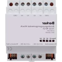
BLC relay insert HVAC
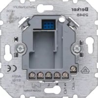
Order-No.: 2912
Operation- and
Assembly Instructions
1 Safety instructions
Electrical equipment may only be installed and fitted by electrically skilled persons.
Failure to observe the instructions may cause damage to the device and result in fire and other hazards.
Danger of electric shock. Always disconnect before carrying out work on the devise or load. At the same time, take into account all circuit breakers that supply dangerous voltage to the device or load.
Danger of electric shock. Device is not suitable for disconnection from supply voltage.
Danger of electric shock on the SELV/PELV installation. Not suitable for switching SELV/PELV voltages.
Danger of electric shock. Do not operate the insert without a cover.
These instructions are an integral part of the product, and must remain with the end customer.
2 Device components
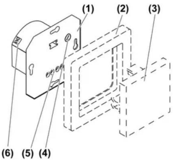
text_image
(1) (2) (3) (4) (5) (6)picture 1
(1) Flush-mounted insert
(2) Frame
(3) Pushbutton cover
(4) Adjuster for run-on time of output HLK
(5) Connection terminals for mains voltage and output Kanal 1
(6) Connection terminals for output HLK for HVAC
3 Function
Intended use
- Output Kanal 1 for switching light
- Output HLK for switching light, fans, air conditioners, thermostats and motors
- Operation with suitable cover
- Installation in appliance box to DIN 49073
Product characteristics
- Output HLK with potential-free NO contact for switching a second electric circuit, not SELV or PELV
- Switch-on delay of output HLK can be switched off
- Run-on time of output HLK adjustable
- Connection of extensions possible
Function with motion detector or presence detector cover
Output Kanal 1
- Output is switched on if motions are detected and the brightness is below the threshold set on the cover.
- Output remains switched on as long as motions are detected.
- Output is switched off if no more motions are detected and the run-on time set on the cover has elapsed.
Output HLK
- Switch-on delay switched on: output is switched on independently of the brightness after 3 minutes if additional motions are detected approx. 2.5 to 3 minutes after the initial detection.
- Switch-on delay switched off: output is switched on independently of brightness if motion is detected.
- Output remains switched on as long as motions are detected.
- Output is switched off if no more motions are detected and the run-on time set on the insert has elapsed.
Behaviour after a mains voltage failure
- Less than 0.2 seconds: switching state is retained
- longer than 0.2 seconds: both channels switch off. The behaviour after mains voltage return depends on the cover used (see instructions for the cover).
4 Operation
Switching on with pushbutton cover (see Accessories)
Operation on the main device, 2-wire extension or on the installation button is identical.
i Extension operation is only possible if there is a cover fitted on the main device.
Outputs are switched off.
■ Press the button.
Output Kanal 1 switches on.
When the switch-on delay for output HLK is switched off, output HLK switches on directly.
When the switch-on delay for output HLK is switched on, output HLK switches on with a time delay, if output Kanal 1 is switched on for longer than 3 minutes.
Switching off with pushbutton cover (see Accessories)
Outputs are switched on.
■ Press the button.
Output Kanal 1 switches off.
Output HLK switches off after the run-on time set on the insert elapses. The run-on time begins as soon as output Kanal 1 has switched off.
Switching on in combination with motion detector or presence detector
Operation is performed with a 2-wire extension or an installation button. Only an overview of the behaviour is provided here. For additional information, please refer to the instructions for the cover in question. Operation with an extension is only possible is there is a cover fitted on the main device.
Outputs are switched off.
■ Press extension.
Output Kanal 1 switches on.
When the switch-on delay for output HLK is switched off, output HLK switches on directly.
When the switch-on delay for output HLK is switched on, output HLK switches on after a time delay of 3 minutes, if no additional motions are detected for approx. 2.5 to 3 minutes after the extension is operated.
Switching off in combination with motion detector or presence detector
i Combination with motion detector: outputs cannot be switched off.
i Combination with presence detector: the output HLK cannot be switched off.
Outputs are switched on.
■ Press extension.
Output Kanal 1 switches off for 3 minutes. Any motions that are detected extend the time.
During these 3 minutes output Kanal 1 can only be switched on again via the extension.
5 Information for electrically skilled persons
5.1 Fitting and electrical connection

DANGER!
Electrical shock when live parts are touched.
Electrical shocks can be fatal.
Before carrying out work on the device or load, disengage all the corresponding circuit breakers. Cover up live parts in the working environment.
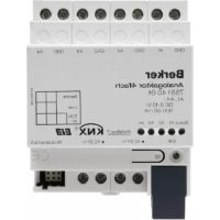
Connecting and mounting the insert
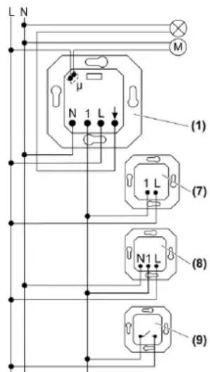
text_image
L N M μ N 1 L (1) 1 L (7) N1 L (8) (9)picture 2: Connection diagram with optional extensions
(1) Flush-mounted insert
(7) Extension insert, 2-wire
(8) Extension insert, 3-wire
(9) Installation button, NO contact
i Outputs Kanal 1 and HLK are not protected internally. For device protection, connect a 10 A miniature circuit breaker upstream.
■ Connect insert according to connection diagram (picture 2).
i Output HLK can be used to switch a second external conductor.
For extension units use the electric circuit of output Kanal 1.
i Illuminated installation buttons may only be connected if they have a separate N terminal.
■ Connect the extensions, optional.
■ Install insert in appliance box, terminals must be at the bottom.
■ If multiple miniature circuit breakers supply dangerous voltages to the device or load, couple the miniature circuit breakers or label them with a warning, to ensure release is guaranteed.
■ Set run-on time for output HLK (see Commissioning).
■ Attach the frame and the cover.
■ Switch on mains voltage.
5.2 Commissioning

DANGER!
Electrical shock when live parts are touched.
Electrical shocks can be fatal.
Before carrying out work on the device or load, disengage all the corresponding circuit breakers. Cover up live parts in the working environment.
Switching switch-on delay for output HLK on and off
The switch-on delay for output HLK can be switched on or off. In the sate as delivered the switch-on delay is switched on.
There is a pushbutton cover (see Accessories) on the HLK insert.
Outputs Kanal 1 and HLK are switched off.
■ Press button over entire surface for longer than 3 seconds.
When the switch-on delay is switched on for output HLK, only output Kanal 1 is switched on. After 3 seconds the switch-on delay is switched off; output Kanal 1 is switched off again as confirmation.
When the switch-on delay for output HLK is switched off, both outputs are switched on. After 3 seconds the switch-on delay is switched on; both outputs are switched off again as confirmation.
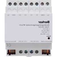
Setting run-on time for output HLK
Output HLK remains switched on for the run-on time, after output Kanal 1 has been switched off or no more motions are detected. The run-on time can be set in five stages between 2 minutes and 120 minutes.
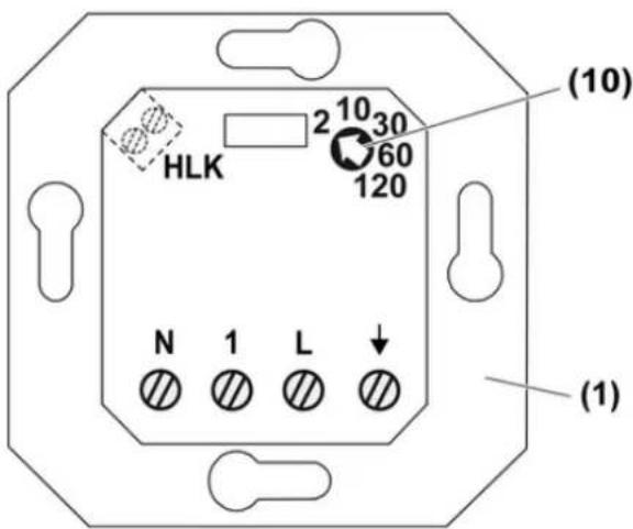
text_image
HLK 2 10 30 60 120 N 1 L (1) (10) (1)picture 3: Adjuster for run-on time of output HLK
(1) Flush-mounted insert
(10) Adjuster for run-on time of output HLK
■ Turn adjuster (10) to the desired time.
6 Appendix
6.1 Technical data
Rated voltage AC 230 V \~
Mains frequency 50 / 60 Hz
Ambient temperature +5 ... +35 °C
Circuit breaker max. 10 A
Contact type μ contact
Switching current at 25 °C, Kanal 1
Ohmic 10 A
Switch-on current max. 4 s at 10% switch-on time
Minimum switching current AC 100 mA
Connected load at 25 °C, Kanal 1
Incandescent lamps 1000 W
HV halogen lamps 1000 W
Inductive transformers 750 VA
Tronic transformers 750 W
Fluorescent lamps, uncompensated 500 VA
Electronic ballast Type-dependent
Connection, Kanal 1
Single stranded max. 4 mm²
finely stranded without conductor sleeve
finely stranded with conductor sleeve
HLK
Follow-up time
Switching voltage
Minimum switching voltage
Switching current for AC 230 V \~, 25 °C, HLK
Ohmic
Switch-on current
Minimum switching current AC 100 mA
Connected load for 230 V \~, 25 °C, HLK
Incandescent lamps
HV halogen lamps
15 A
max. 4 mm²
max. 2.5 mm²
approx. 2, 10, 30, 60, 120 min
AC 230 V \~
AC 12 V\~
6 A
max. 2.1 A
800 W
750 W
Motors 450 VA
Connection, HLK
Single stranded 1.5 mm²
finely stranded without conductor sleeve max. 1 mm ^4
finely stranded with conductor sleeve max. 1 mm ^4
Number of extension units
Extension insert, 2-wire unlimited
Extension insert, 3-wire 10
Non-illuminated installation buttons unlimited
Total length power cable max. 100 m
Total length of extension unit cable max. 100 m
6.2 Accessories
BLC button Order-No. 1761..
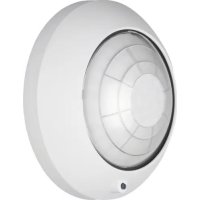
For presence-dependent control, a motion detector, ceiling motion detector or presence detector of the BLC system can be fitted on the BLC insert.
The insert can also be integrated into a radio bus installation with a BLC radio button.
6.3 Warranty
We reserve the right to make technical and formal changes to the product in the interest of technical progress.
Our products are under guarantee within the scope of the statutory provisions.
If you have a warranty claim, please contact the point of sale or ship the device postage free with a description of the fault to the appropriate regional representative.