2948 - Switch BERKER - Free user manual and instructions
Find the device manual for free 2948 BERKER in PDF.
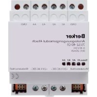
| Product type | Timed switch (timer) for lighting |
| Brand | Berker |
| Model | 2948 |
| Rated voltage | AC 230 V, 50 Hz |
| Max power (incandescent lamp) | 1000 W |
| Max power (high voltage halogen) | 1000 W |
| Max power (low voltage halogen with TRONIC transformer) | 750 W |
| Max power (low voltage halogen with conventional transformer) | 750 VA (min. load 85%) |
| Max power (fluorescent without compensation) | 500 VA |
| Max power (fluorescent with parallel compensation) | 400 VA |
| Max power (fluorescent duo) | 1000 VA |
| Relay output type | 1 potential-free normally open contact |
| Number of terminals | 6 screw terminals + adapter connector |
| Max conductor cross-section | 2.5 mm² or 2 x 1.5 mm² |
| Max circuit breaker | 16 A |
| Mounting | Flush-mounted in 60 mm box (recommended depth) |
| Functions | Timer with time delay, optional twilight detector, two mechanical secondary controls |
| Applications | Automatic lighting switching |
| Safety | Installation by a qualified electrician; not suitable for disconnection from mains supply |
| Warranty | Legal compliance (return to customer service with defect description) |
Frequently Asked Questions - 2948 BERKER
User questions about 2948 BERKER
0 question about this device. Answer the ones you know or ask your own.
Ask a new question about this device
Download the instructions for your Switch in PDF format for free! Find your manual 2948 - BERKER and take your electronic device back in hand. On this page are published all the documents necessary for the use of your device. 2948 by BERKER.
USER MANUAL 2948 BERKER
Operating Instructions
text_image
L N L1 L2 N- Warning 10
- Installation Instructions 12
- Connection 14
- Acceptance of guarantee 17
1. Warning
Caution! The installation and assembly of electrical equipment may only be
performed by a skilled electrician. Not suitable for disconnecting.
This timer has been designed for the automatic switching of lights. If they are used for any other purposes which may entail hazards (e.g. switching heaters) such hazards will have to be eliminated by the user by taking additional suitable safety measures.
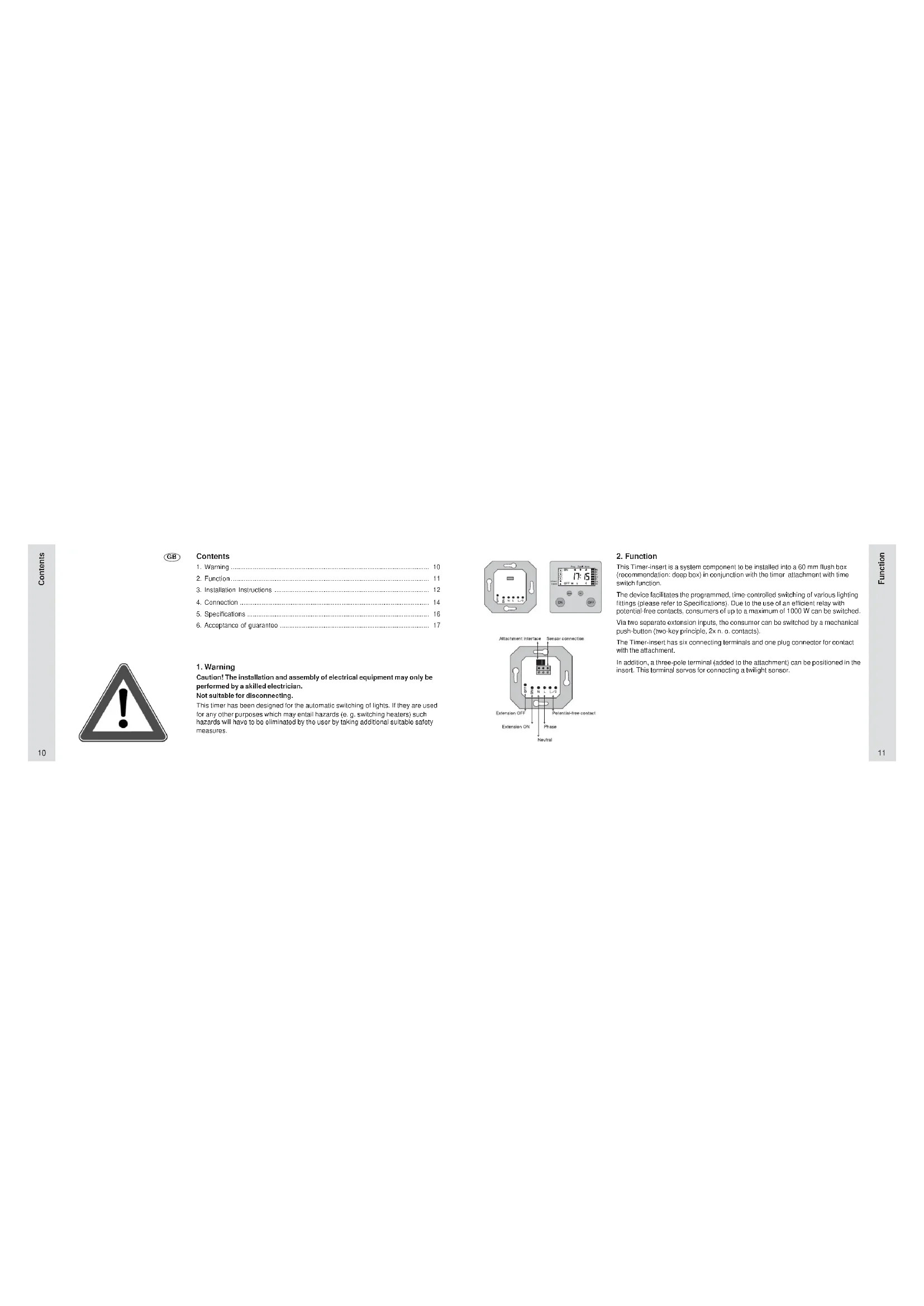
2. Function
This Timer-insert is a system component to be installed into a 60 mm flush box (recommendation: doop box) in conjunction with the timer attachment with time switch function.
The device facilitates the programmed, time-controlled switching of various lighting fittings (please refer to Specifications). Due to the use of an efficient relay with potential-free contacts, consumers of up to a maximum of 1000 W can be switched.
Via two separate extension inputs, the consumer can be switched by a mechanical push-button (two-key principle, 2x n. o. contacts).
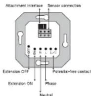
The Timer-insert has six connecting terminals and one plug connector for contact with the attachment.
In addition, a three-pole terminal (added to the attachment) can be positioned in the insert. This terminal serves for connecting a twilight sensor.

A
B
3. Installation Instructions
Important: The sensor line carries protective low voltage (SELV). Please observe the installation procedures as specified by VDE 0100.
Connecting the Sensor:
Buried Wiring (Figure A):
Choose suitable cable for buried installation of the sensor line.
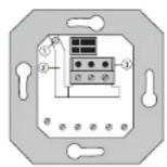
Recommendation: J-Y(ST)Y 2x2x0.6 mm telephone cable. The individual wires of the sensor line should be put through flexible insulating tubing (added to the attachments with sensor evaluation). Then, together with the flexible insulating tubing, push the line through entrance 0 of the insert and through duct 0 to terminal 0.
The insulating tubing must cover the individual wires from the cable sheath to the connecting terminal. Put the connecting terminal (added to the attachments with sensor evaluation) in the insert as shown in the illustration.
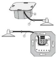
Surface Wiring (Figure B):
Lead sensor line ① behind the supporting plate (between the wall and the supporting plate) through opening ② into duct ③ of the insert. The line must be led directly through the duct to connecting terminal ④. The line must be precisely in the duct and must not form any loops towards the 230 V connecting terminal space.

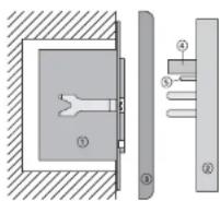
Connect the sensor line as shown in the opposite illustration.
Wire marking:
Sensor: 'Earth' = marked.
Adapter, extension line:
'Twilight' = marked.
'Earth' = middle wire.
The Timer-insert can only be used in conjunction with the Timer attachment with time switch function.
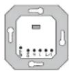
Timer-insert © is provided for installation in a 60 mm flush box
(recommendation: deep box).
The connecting terminals of the insert must be down.
Plug attachment ② onto the insert together with frame ③.
Electrical contacting is established through plug (9) and 30.
(For the description, installation and connection of the attachment, please refer to separate instructions.)
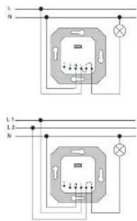
text_image
L N L1 L2 N- Timer insert Connection
Connect phase L with the relay input ('jumper').
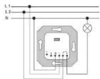
Two-phase connection
The timer insert is provided with potential-free contacts.
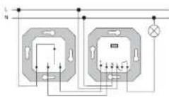
Connection with mechanical extension
Connect phase L with the relay input ('jumper')
5. Specifications
Rated voltage :230 V AC, 50 Hz (neutral conductor required)
Switching Capacity
Incandescent lamps :1000 W
Halogen HV lamps : 1000 W Halogen LV lamps with
TRONIC transformers :750 W
Convent. transformers :750 VA
Conv. transformer with at least 85 % rated load.
Fluorescent lamps
Uncompensated :500 VA
Shunt-compensated (47μF):400 VA
Twin-lamp circuit:1000 VA
Energy-saving lamps: When using energy-saving lamps,
mind high surge peak currents.
Check lamps for suitability prior to use
Relay output: 1 potential-free n. d. contact Not suitable for disconnecting
Switching time interval :1 minute min.
Connecting terminals : Screw terminals for 2.5 mm ^2 max. or 2 x 1.5 mm ^2
Automatic cut-out :16 A max.
6. Acceptance of guarantee
We accept the guarantee in accordance with the corresponding legal provisions.
Please return the unit postage paid to our central service department giving a brief description of the fault:
Telephone:149 (D) 23 55/90 5-0
Telefax: +49 (0) 23 55 / 90 5-111
NL Inhoudsopgave
text_image
L N L1 L2 Ntext_image
L N L1 L2 NCE The CE-sign is a free trade sign addressed exclusively to the authorities and does not include any warranty of any properties.