75314007 - Switch BERKER - Free user manual and instructions
Find the device manual for free 75314007 BERKER in PDF.
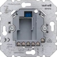
| Product type | Switch actuator for instabus EIB system |
| Brand | Berker |
| Model | 75314007 |
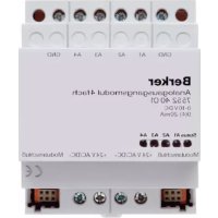
| Number of channels | 4 channels (standard model) |
| Power supply | 21 - 32 V DC via instabus EIB bus |
| Power consumption | 150 mW typical |
| Mounting width | 72 mm (4 modules) |
| Ambient temperature | -5 °C to +45 °C |
| Storage temperature | -25 °C to +70 °C |
| Switched voltage (outputs A1-A4) | 230 V AC / 400 V AC |
| Breaking current (230 V AC) | 16 A / AC1 ; 10 A / AC3 |
| Switching power (incandescent lamps) | 2500 W |
| Contact type | Potential-free make contact (μ-contact) |
| Main functions | Switching of electrical loads via EIB bus; switching position indicators; manual operation of relays |
| Bus connection | Instabus terminal |
| Mains connection | Screw terminal 1.5-4 mm² (solid wire) or 0.75-4 mm² (stranded wire) |
| Safety | Installation by a qualified electrician; disconnect power before intervention |
| Maintenance and cleaning | Do not clean with aggressive products; use a dry cloth |
| Spare parts and repairability | Not specified; contact Berker customer service |
| General information | Compliant with EIBA directives; requires software for configuration |
Frequently Asked Questions - 75314007 BERKER
User questions about 75314007 BERKER
0 question about this device. Answer the ones you know or ask your own.
Ask a new question about this device
Download the instructions for your Switch in PDF format for free! Find your manual 75314007 - BERKER and take your electronic device back in hand. On this page are published all the documents necessary for the use of your device. 75314007 by BERKER.
USER MANUAL 75314007 BERKER
text_image
L1 L2 L3 N A ② ① + instabus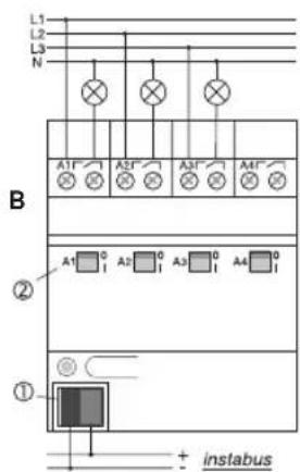
text_image
L1 L2 L3 N A1' A2' A3' A4' ② A1 0 I A2 0 I A3 0 I A4 0 ① + instabusAnschluss
D
text_image
L1 L2 L3 N A1 A2 A3 A4 C ① + instabus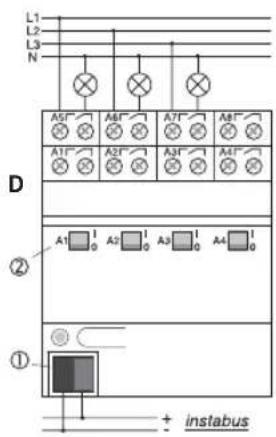
text_image
L1 L2 L3 N A5* A6* A7* A8* A1* A2* A3* A4* ② A1 1 0 A2 1 0 A3 1 0 A4 1 0 ① + instabusAnschluss
D
natural_image
Hand holding a tool interacting with a mechanical component (no visible text or symbols)G

natural_image
Hand holding a mechanical component with directional arrows indicating movement (no text or symbols)Operating Instructions
4-channel switching actuator
4-channel switching actuator, C-load
4-channel switching actuator, C-load
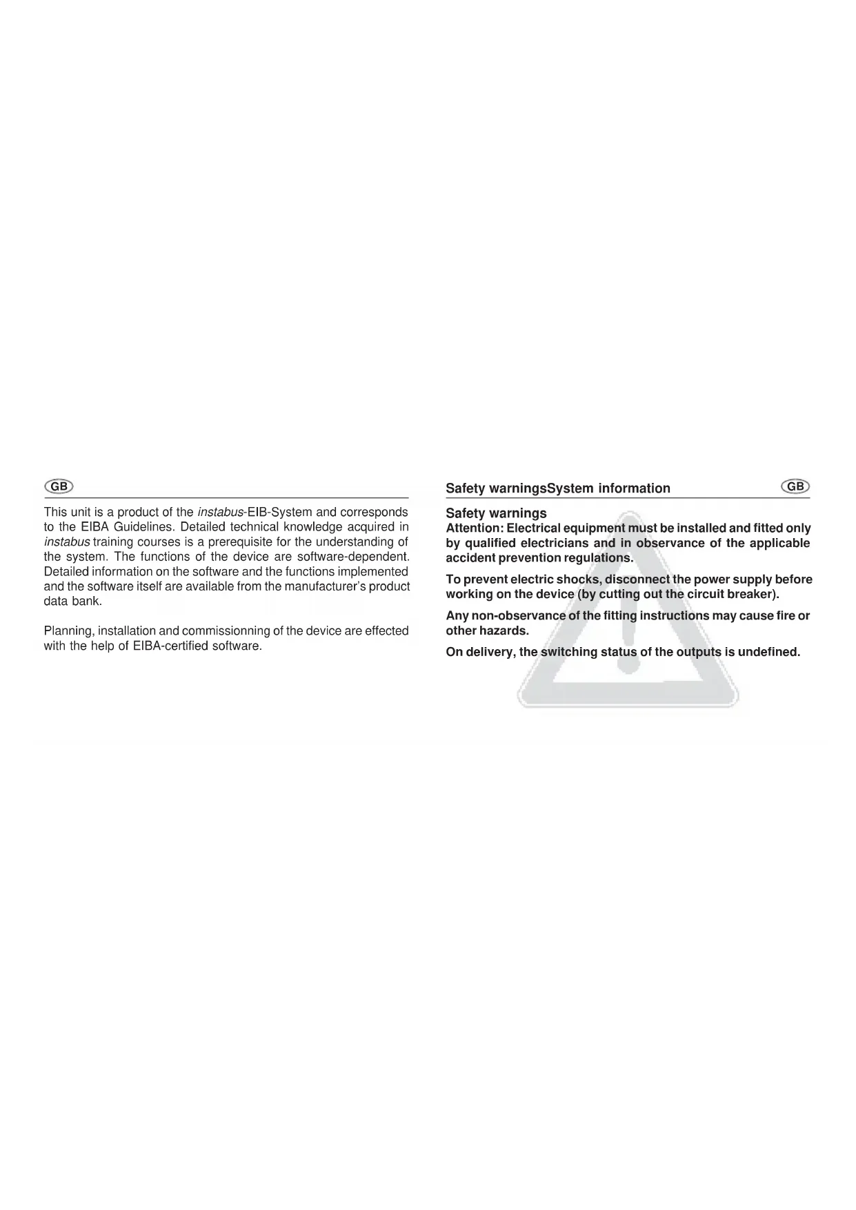
This unit is a product of the instabus-EIB-System and corresponds to the EIBA Guidelines. Detailed technical knowledge acquired in instabus training courses is a prerequisite for the understanding of the system. The functions of the device are software-dependent. Detailed information on the software and the functions implemented and the software itself are available from the manufacturer's product data bank.
Planning, installation and commissioning of the device are effected with the help of EIBA-certified software.
Safety warningsSystem information
GB
Safety warnings
Attention: Electrical equipment must be installed and fitted only by qualified electricians and in observance of the applicable accident prevention regulations.
To prevent electric shocks, disconnect the power supply before working on the device (by cutting out the circuit breaker).
Any non-observance of the fitting instructions may cause fire or other hazards.
On delivery, the switching status of the outputs is undefined.
GB
The 4-channel, 4-channel C-load, 6-channel, 8-channel and 8-channel C-load switching actuators with potential-free contacts can be used for switching electrical consumers via the instabus EIB. The switching commands come from touch sensors or from binary inputs of the instabus EIB system.
The 4 channel, 4 channel C-load, 8-channel C-load and 8-channel switching actuators (outputs A1 - A4) are equipped with switching status indicators which are used at the same time for manual operation of the relays independent of the instabus EIB.
The switching contacts of C-load switching actuators are designed especially for capacitive loads and the corresponding high inrush currents (see technical specifications).
The devices do not require an additional power supply.
InstructionsFunction
GB
- The outputs A1 - A4 and A5 - A8 of the 8-channel actuator have different maximum switching capacities.
- In the event of control from a central telegram, the relay outputs of an actuator switch with a slight delay.
- Do not connect three-phase motor to the actuators.
- Manual operation of the relays is independent of bus conditions and not affecting the switching objects. For this reason, a software-disabled output can nevertheless be switched by hand.
- The use of 230 V and SELV at different outputs of an actuator is not permitted.
GB
Connection
text_image
L1 L2 L3 N A ② ① + instabus
text_image
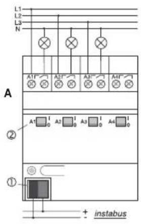
L1 L2 L3 N A1 A2 A3 A4 B ② A1 0 A2 0 A3 0 A4 0 ① + instabusConnection
GB
4-channel switching actuator (fig. A), 4-channel C-load switching actuator (fig. B).
Connection to the bus is by means of the bus connector ①.
The switching statuses of the relays are indicated by the switch position indicators ②. They are used at the same time for manual operation of the relays independent of the EIB.
Important: Observe that switch status indicators ② in the C-load actuator (shown on the right) are inverted for constructional reasons.
The actuators are connected as shown in the schematic.
The actuator outputs can be connected to different phase conductors.
GB
Connection
text_image
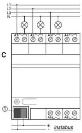
L1 L2 L3 N A1F A2F A3F A4F C ① + instabus
text_image
L1 L2 L3 N A5" A6" A7" A8" A1" A2" A3" A4" D ② A1 1 0 A2 1 0 A3 1 0 A4 1 0 ① + instabusConnection
GB
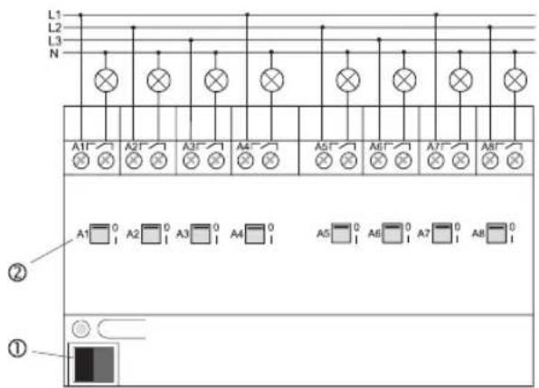
6-channel actuator (fig. C), 8-channel actuator (fig. D).
Bus connection is by means of the bus connector ①.
In the 8-channel actuator, the switching statuses of the relays of outputs A1 - A4 are indicated by the switch position indicators ②. They are used at the same time for manual operation of the relay outputs A1 - A4 of the 8-channel actuator independent of the EIB.
The actuators are connected as shown in the schematic.
The actuator outputs can be connected to different phase conductors.
GB
Connection
E
text_image
L1 L2 L3 N A1 A2 A3 A4 A5 A6 A7 A8 ② A1 0 A2 0 A3 0 A4 0 A5 0 A6 0 A7 0 A8 0 ①Connection
GB
8-channel C-load switching actuator (fig. E).
Bus connection is by means of the bus connector ①.
In the 8-channel actuator, the switching statuses of the relays are indicated by the switch position indicators ②. These are used at the same time for manual operation of the relays independent of the EIB
Important: Observe that the switching status indicators ② in the C-load actuator are inverted for constructional reasons.
The actuators are connected as shown in the schematic.
The actuator outputs can be connected to different phase conductors.
GB
Cap
F
natural_image
Illustration of a hand holding a tool over a document or paper (no text or symbols visible)G

natural_image
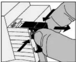
Illustration of a hand inserting a small object into a device (no text or symbols visible)Slide the cap over the bus terminal with the bus line at the bottom (fig. F) until it is heard to engage.
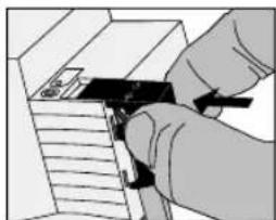
Remove the cap by pressing against the sides and by pulling it out at the same time (fig. E).
Technical characteristics
GB
General
instabus EIB supply voltage :21 - 32 V DC
instabus EIB power rating :typically 150 mW
instabus EIB Connection
: instabus connector
Mains connection : screw terminals
1.5 – 4 mm ^2 solid wire or 2 x 01.5 – 2.5 mm ^2 solid wire 0.75 – 4 mm ^2 stranded without wire end ferrule or 0.5 – 2.5 mm ^2 stranded with wire end ferrule
GB
General
Output contact type : potential-free n.o. contacts
(μ-Contact)
Ambient temperature : -5 °C ... +45 °C
Storage temperature : -25 °C ... +70 °C
Mounting width
only 8-channel C-load
switching actuator : 144 mm (4 modules)
all other actuator : 72 mm (4 modules)
Technical characteristics Technical characteristics
GB
Switching actuator outputs, 4-channel and 8-channel (outputs A1 – A4)
Switched voltage : 230 V AC, 400 V AC
Switched current at 230 V AC : 16 A / AC1; 10 A / AC3
Switched current at 400 V AC : 10 A / AC1; 6 A / AC3
Switching capacity
incandescent lamps : 2500 W
fluorescent lamps
non-compensated : 2500 W
parallel compensation : 1300 W / 140 μF
lead-lag circuit : 2 x 2500 W
HV halogen lamps : 2500 W
LV halogen lamps : 500 VA
Tronic transformers : 1300 VA
GB
Switching actuator outputs, 6-channel and 8-channel (outputs A5 – A8)
Switched voltage : 230 V AC
Switched current at 230 V AC : 6 A / AC1
Switching capacity
incandescent lamps : 1000 W
fluorescent lamps
non-compensated, cos φ=0.5:500 W
parallel compensation, cos φ = 1 : 2 x 58 W / 14 μF
3 x 36 W / 14 μF
6 x 18 W / 14 μF
lead-lag circuit, cos φ = 1 : 1000 W
Siemens electronic ballast
58 W fluorescent lamp : 10 units
36 W fluorescent lamp : 15 units
18 W fluorescent lamp : 15 units
Technical Data Technical Data
GB
4-channel C-load and and 8-channel C-load switching actuator outputs
Switched voltage : 230 V AC, 400 V AC
Switched current at 230 V AC : 16 A / AC1; 10 A / AC3
Switched current at 400 V AC : 10 A / AC1; 6 A / AC3
Switching capacity
incandescent, HV halogen lamps : 3680 W
LV halogen lamps : 2000 VA
Tronic transformers : 2500 W
fluorescent lamps
non-compensated, cos φ = 0.5 : 3680 W
parallel compensation, cos φ = 1 : 2500 W / 200 μF
lead-lag circuit, cos φ = 1 : 2 x 3680 W
Mercury / sodium vapour lamp
non-compensated; parallel compensation : 3680 W / 200 μF
Technical specifications subject to change
GB
Acceptance of guarantee
Our products are under guarantee within the scope of the statutory provisions.
Please return the unit postage paid to our central service department giving a brief description of the fault:
CE The CE-sign is a free trade sign addressed exclusively to the authorities and does not include any warranty of any properties.
text_image
L1 L2 L3 N A ② ① + instabus
text_image
L1 L2 L3 N A1' A2' A3' A4' ② A1 0 A2 0 A3 0 A4 0 ① + instabusAansluiting
NL
text_image
L1 L2 L3 N A5' A6' A7' A8' A1' A2' A3' A4' ② A1 1 0 A2 1 0 A3 1 0 A4 1 0 ① + instabusAansluiting
NL
natural_image
Illustration of a hand holding a tool over a document or paper (no text or symbols visible)G

natural_image
Illustration of a hand inserting a component into a device (no text or symbols visible)Voeding instabus EIB :21 - 32 V DC
Vermogensopname instabus EIB :typ. 150 mW
Aansluiting instabus EIB
text_image
L1 L2 L3 N A ② ① + instabus
text_image
L1 L2 L3 N A1' A2' A3' A4' ② ① + instabusConnexionConnexion
F
text_image
L1 L2 L3 N A1 A2 A3 A4 C ① + instabus
text_image
L1 L2 L3 N A5* A6* A7* A8* A1* A2* A3* A4* D ② A1 1 0 A2 1 0 A3 1 0 A4 1 0 ① + instabusConnexionConnexion
F
natural_image
Illustration of a hand holding a tool over a document or paper (no text or symbols visible)G

natural_image
Illustration of a hand inserting a component into a device (no text or symbols visible)couplage duo : 2 x 2500 W
text_image
L1 L2 L3 N A ② ① + instabus
text_image
L1 L2 L3 N A1' A2' A3' A4' ② A1 0 A2 0 A3 0 A4 0 ① + instabusTilkopling
N
Koplingsaktuator 4-dobbelt (figur A), koplingsaktuator 4-dobbelt C-last (figur B).
text_image
L1 L2 L3 N A5' A6' A7' A8' A1' A2' A3' A4' ② A1 1 0 A2 1 0 A3 1 0 A4 1 0 ① + instabusTilkopling
N
Koplingsaktuator 6-dobbelt (figur C), koplingsaktuator 8-dobbelt (figur D).
natural_image
Illustration of a hand holding a tool over a document or paper (no text or symbols visible)G
natural_image
Illustration of a hand inserting a component into a device (no text or symbols visible)Skyv dekselet over bussklemmen med bussledningene ført ut nede (fig. F) til det smetter merkbart på plass.
Siemens el. drosselspole
58 W lysstofflampe : 10 stk.
36 W lysstofflampe : 15 stk.
18 W lysstofflampe : 15 stk.
text_image
L1 L2 L3 N A ② ① + instabus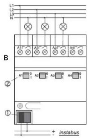
text_image
L1 L2 L3 N A1 A2 A3 A4 B ② ① + instabusConexiónConexión
E
text_image
L1 L2 L3 N A1 A2 A3 A4 C ① + instabus
text_image
L1 L2 L3 N A5* A6* A7* A8* A1* A2* A3* A4* D ② A1 1 0 A2 1 0 A3 1 0 A4 1 0 ① + instabusConexiónConexión
E
natural_image
Illustration of a hand holding a tool over a document or paper (no text or symbols visible)G