75424004 - Electronic module BERKER - Free user manual and instructions
Find the device manual for free 75424004 BERKER in PDF.
| Product type | Analog input module |
| Brand | Berker |
| Model | 75424004 |
| Number of analog inputs | 4 |
| Input signals | Voltage 0-1 V DC, 0-10 V DC; Current 0-20 mA DC, 4-20 mA DC |
| External power supply | 24 V AC ±10%, max. 170 mA |
| Consumption on system connector | typ. 150 mW |
| Power supply for detectors (+U_s) | 24 V DC, max. 100 mA |
| Mounting width | 4 modules / 72 mm |
| Weight | approx. 150 g |
| Protection type | IP 20 (EN 60529) |
| Ambient temperature | -5 °C to +45 °C |
| Storage/transport temperature | -25 °C to +70 °C |
| Permissible humidity | max. 93% RH, non-condensing |
| Input and power connections | Screw terminals, cross-section 0.5-4 mm² (solid) or 0.34-4 mm² (stranded without ferrule) |
| Connection to KNX/EIB device | 6-pin system connector (supplied) |
| Voltage measurement impedance | approx. 18 kΩ |
| Current measurement impedance | approx. 100 Ω |
| Status LED | Red: on = fault or self-test OK depending on phase; fast/slow flashing = initialization or unconfigured |
| Mounting | On DIN rail 35 x 7.5 mm (EN 50022) |
| Maintenance and cleaning | Clean with a dry cloth; do not use abrasive products |
| Safety | Installation by a qualified electrician; observe fire prevention regulations; do not connect U_s and GND to other devices |
| Repairability and spare parts | Contact Berker after-sales service in case of defect, send postage paid with description of defect |
| Detector compatibility | KNX/EIB weather station (ref. 7541 40 03) or KNX/EIB analog input (ref. 7541 40 04); preconfigured detectors: brightness (WS 10H), twilight (WS 10D), temperature (WS 10T), wind (WS 10W), rain (WS 10R), ambient humidity/temperature |
Frequently Asked Questions - 75424004 BERKER
User questions about 75424004 BERKER
0 question about this device. Answer the ones you know or ask your own.
Ask a new question about this device
Download the instructions for your Electronic module in PDF format for free! Find your manual 75424004 - BERKER and take your electronic device back in hand. On this page are published all the documents necessary for the use of your device. 75424004 by BERKER.
USER MANUAL 75424004 BERKER
Operating Instructions
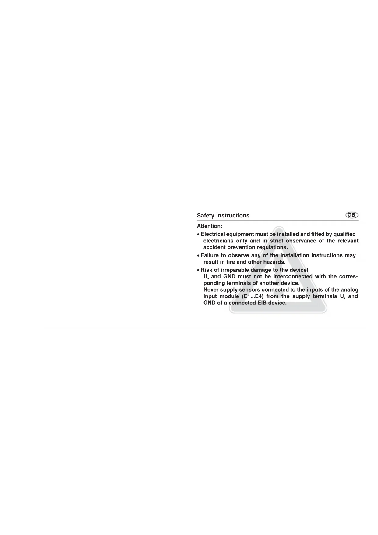
- Electrical equipment must be installed and fitted by qualified electricians only and in strict observance of the relevant accident prevention regulations.
- Failure to observe any of the installation instructions may result in fire and other hazards.
- Risk of irreparable damage to the device!
U_s and GND must not be interconnected with the corresponding terminals of another device.
Never supply sensors connected to the inputs of the analog input module (E1...E4) from the supply terminals U_s and GND of a connected EIB device.
GB
Function
- This analog input module extends an EIB weather station 'Komfort' order no. 7541 40 03 or an EIB analog input, order no. 7541 40 04 by four additional sensor inputs for analog transducers.
- Measuring data evaluation and limit processing take place in the KNX/EIB device.
- The analog input module accepts both voltage and current signals: Voltage signals: 0 ... 1 V DC 0 ... 10 V DC Current signals: 0 ... 20 mA DC 4 ... 20 mA DC
- The current inputs 4 ... 20 mA can be monitored for wire breakage (parameter setting).
Installation
GB
The device is snap-fastened on a 35 x 7.5 mm rail as per EN 50022.
An analog input module must be connected to the EIB device by means of the 6-pole system connector only (supplied with the analog input module).
For operation, the analog input module needs an external 24 V power supply unit, e.g. order no. 7591 00 01.
In addition, the unit can supply power to connected sensors as e.g. WS 10W, WS 10R, their heating circuits or to the connected KNX/EIB device.
GB
Power supply of connected sensors
- The connected sensors can be supplied from terminals +U_s and GND (see fig. ①). These terminals are provided in duplicate and internally interconnected.
- The total current consumption of all sensors supplied this way must not exceed 100 mA.
- In the event of overload or short-circuit between +U_s and GND, the power will be switched off. After removal of the fault, the power is switched on again automatically.
- Sensors connected can also be supplied externally (e.g. if their current consumption exceeds 100 mA). In such case, they must be connected between terminals E1...E4 and GND.
Power supply of connected sensors
GB
Attention!
Risk of irreparable damage to the device!
U_s and GND must not be interconnected with the corresponding terminals of another device.
Never supply sensors connected to the inputs of the analog input module (E1...E4) from the supply terminals U_s and GND of a connected EIB device.
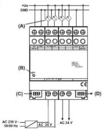
Wiring diagram
①
text_image
+Us GND (A) (B) (C) (D) AC 230 V~ 50/60 Hz AC 24 V AC 24 VConnection
+Us : power supply of external transducers
GND : ref. potential for +U _s and inputs E1 ... E4
E1 ... E4 : measured-value inputs
24 V AC : external power supply voltage
(A) : transducers
(B) : status LED (red)
(C): system connector, 6-pole, for module connection
(D) : system connector, 6-pole, for future extensions (no function)
Please observe the following basic rules when installing an analog input module:
- Replacement of a module (e.g. in case of defect) by one of the same type can be effected during operation of the system (for this purpose, disconnect the module from the power supply). After replacement, the KNX/EIB device will reset after abt. 25 s. All inputs and outputs of the KNX/EIB device and the modules connected are then re-initialized and reset to their original state.
- Removing or adding modules without adapting their project configuration and subsequent downloading into the KNX/EIB device is not allowed as this will result in system failure.
Status LED
During commissioning of the module:
On : Module ready for operation (self-test OK).
Quickly blinking : Module initialization in progress
Slowly blinking : Module not configured (in EIB device)
Off : Module initialized and in operation
Precondition: LED must have been on beforehand!
Normal operation:
On : Module not ready for operation (fault condition)
Off : Modul initialized and in operation.
Precondition: LED must have been on beforehand!
Slowly blinking = 1/s; quickly blinking = 2/s
GB
Sensors suitable for connection
Connection to a KNX/EIB weather station:
For any of the following transducers, the software provides preset values. If other sensors are used, the parameters to be set must be determined beforehand.
Type Use Model Order no.
Brightness outdoor WS 10H 7590 00 53
Twilight outdoor WS 10D 7590 00 55
Temperature outdoor WS 10T 7590 00 54
Wind outdoor WS 10W 7590 00 50
Rain outdoor WS 10R 7590 00 52
Humidity/temp. Indoor 7590 00 56
Sensors suitable for connection
GB
Connection to a KNX/EIB analog input:
The parameters to be set for connected sensors must be determined beforehand.
Type Use Model Order no.
Brightness outdoor WS 10H 7590 00 53
Twilight outdoor WS 10D 7590 00 55
Temperature outdoor WS 10T 7590 00 54
Wind outdoor WS 10W 7590 00 50
Rain outdoor WS 10R 7590 00 52
Humidity/temp. Indoor 7590 00 56
Technical Data
Power supply
Supply voltage : AC 24 V ± 10 %
Current consumption : 170 mA max.
Current consumption
on system connector : typically 150 mW
Ambient temperature : -5 °C ... +45 °C
Storage/transport temp. : -25 °C ... +70 °C
Humidity
Ambient/storage/transport : 93 % r.h. max., no condensation
Protective system : IP 20 as per EN 60529
Installation width : 4 modules / 72 mm
Weight : approx. 150 g
Technical Data
Connections
Inputs, power supply : screw terminals
single-wire : 0.5 mm ^2 to 4 mm ^2
stranded wire (without ferrule) : 0.34 mm ^2 to 4 mm ^2
stranded wire (with ferrule) : 0.14 mm ^2 to 2.5 mm ^2
Connection to KNX/EIB device : 6-pole system connector
Sensor inputs
Number : 4x analog
Evaluable sensor signals : 0 ... 1 V DC, 0 ... 10 V DC,
0 ... 20 mA, 4 ... 20 mA
Voltage measurement impedance : approx. 18 kΩ
Current measurement impedance : approx. 100 Ω
External sensor power supply (+U_s) : 24V DC, 100mA max.
Subject to technical modifications.
GB
Acceptance of guarantee
Our products are under guarantee within the scope of the statutory provisions.
Please return the unit postage paid to our central service department giving a brief description of the fault:
The €-sign is a free trade sign addressed
exclusively to the authorities and does not
include any warranty of any properties.