75514001 - Electrical automation BERKER - Free user manual and instructions
Find the device manual for free 75514001 BERKER in PDF.

| Product Type | 4-channel analog actuator |
| Brand | Berker |
| Model | 75514001 |
| Category | Electrical automation |
| Power Supply | 24 V AC ±10%, max. 308 mA |
| KNX/EIB Bus Voltage | 21 - 32 V DC |
| Bus Power Consumption | 150 mW typical |
| Number of Analog Outputs | 4 |
| Output Ranges | 0...1 V, 0...10 V, 0...20 mA, 4...20 mA |
| Minimum Load for Voltage Output | 1 kΩ |
| Maximum Load for Current Output | 500 Ω |
| Connections | Outputs and power supply: screw terminals; bus: KNX connection and tapping terminal |
| Mounting Width | 4 modules / 72 mm |
| Weight | approx. 180 g |
| Ambient Temperature | -5 °C to +45 °C |
| Storage/Transport Temperature | -25 °C to +70 °C |
| Humidity | max. 93% RH, non-condensing |
| Protection Type | IP20 according to EN 60529 |
| Main Functions | Conversion of KNX telegrams into analog signals for HVAC control; expandable to 8 outputs with module 7552 40 01; forced control; deactivation of unused outputs; short-circuit monitoring |
| Safety | Installation by qualified electrician only; do not connect electronic ballasts or transformers with 1-10 V input; do not apply external voltages to outputs; do not connect GND terminals between actuator and module (risk of destruction) |
| Maintenance and Cleaning | Clean with a dry, lint-free cloth. Do not use abrasive products or solvents. Disconnect power before any maintenance. |
Frequently Asked Questions - 75514001 BERKER
User questions about 75514001 BERKER
0 question about this device. Answer the ones you know or ask your own.
Ask a new question about this device
Download the instructions for your Electrical automation in PDF format for free! Find your manual 75514001 - BERKER and take your electronic device back in hand. On this page are published all the documents necessary for the use of your device. 75514001 by BERKER.
USER MANUAL 75514001 BERKER
Operating Instructions
B.
Berker
instabus® KNX E13
4-channel analog actuator
This device is a product of the instabus-KNX/EIB system and complies with KNX directives.
Detailed technical knowledge obtained in instabus training courses is a prerequisite to proper understanding.
The functionality of this device depends upon the software.
Detailed information on loadable software and attainable functionality as well as the software itself can be obtained from the manufacturer's product database.
Planning, installation and commissioning of the unit is effected by means of KNX-certified software.
An updated version of the product database and the technical de - scriptions are available in the Internet at www.berker.de
GB
Safety instructions
Attention
- Electrical equipment must be installed and fitted only by qualified electricians and in strict observance of the applicable accident prevention regulations.
- Failure to observe any of the installation instructions may result in fire or other hazards.
- Do not connect electronic ballasts or electronic transformers with 1-10 V control input to the outputs.
- Do not connect external voltages to the outputs.
Connected components must ensure safe separation from other voltages.
- Do not connect the GND terminals with terminals of the same designation in an analog actuator module (risk of irreparable damage).
Function

- The EIB analog actuator has 4 analog outputs and converts KNX/EIB-telegrams (1-byte and 2-byte telegrams) into analog output signals.
- With these analog output signals, actuators used for heating, ventilation and air conditioning purposes are enabled to adapt their output variables in acc. with informations received from the bus and to be used within control processes.
- The outputs are software-parameterized for voltage or current signals.
Voltage outputs: 0...1 V, 0...10 V
Current outputs: 0...20 mA 4...20 mA
• Voltage outputs are monitored for short-circuits. - The output state is indicated by the status LED.
GB
Function
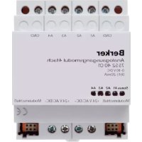
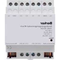
- With the 4-channel analog actuator module, order no. 7552 40 01, the number of analog outputs can be increased by 4 outputs to 8 outputs. The device is connected by means of a system connector.
- The output variables can be subject fo forced control.
• Non used outputs can be deactivated.
The device is snap-fastened on a DIN rail 35 x 7,5 mm as per EN 50022.
The device can only be connected to an analog actuator module by means of a 6-pole system connector (supplied with the analog actuator module).
The EIB analog actuator needs an external 24 V power supply for operation, e.g. the. power supply unit, e.g order no. 7591 00 01. This unit can also supply a connected analog actuator module or other devices.
For easy connection, there are two pairs of internally connected power supply terminals (marked by a dot “•”).
GB
Connectable analog actuators
Safety warnings
- Do not connect electronic ballasts or electronic transformers with 1-10 V control input to the outputs.
- Do not connect external voltages to the outputs.
Connected components must ensure safe separation from other voltages.
- The GND terminals must not be connected with the terminals of the same designation of an of an analog actuator module (risk of irreparable damage!).
Connectable analog actuators

- Current outputs may be loaded with 500 max.
• Voltage outputs must be loaded with 1 kΩ min. - The GND terminals of outputs A1...A4 are internally connected.
- In the event of a short-circuit between a voltage output A1 ... A4 and GND, the respective output is deactivated.

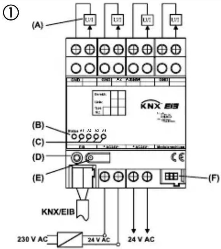
Wiring diagram
text_image
(①) (A) U1 U2 U3 U4 U5 SMD SMD A2 A3 HAB SMD B A1 A2 A3 A4 C E D (E) KNX/EIB 230 V AC 24 V AC F F1 F2 F3 F4 F5 F6 F7 F8 F9 F10 F11 F12 F13 F14 F15 F16 F17 F18 F19 F20 F21 F22 F23 F24 F25 F26 F27 F28 F29 F30 F31 F32 F33 F34 F35 F36 F37 F38 F39 F40 F41 F42 F43 F44 F45 F46 F47 F48 F49 F50 F51 F52 F53 F54 F55 F56 F57 F58 F59 F60 F61 F62 F63 F64 F65 F66 F67 F68 F69 F70 F71 F72 F73 F74 F75 F76 F77 F78 F79 F80 F81 F82 F83 F84 F85 F86 F87 F88 F89 F90 F91 F92 F93 F94 F95 F96 F97 F98 F99 F100Connection

GND : reference potential for outputs A1 ... A4
A1 ... A4 : analog outputs
KNX/EIB : KNX/EIB connecting terminal
24 V AC : external supply voltage
(A) : devices with analog interface
(B) : status LED, tri-coloured (red, orange, green)
(C) : status LEDs of the four analog outputs (yellow)
(D) : programming LED
(E) : programming button
(F) : system connector, 6-pole for connection of an analog actuator module
GB
Installation of an analog actuator module
During the installation of an analog actuator module the following basic rules must be observed:
- The device is designed for the connection of one analog actuator module maximum.
- An extension module can be replaced by one of the same type (e.g. in case of defect) while the system is in operation (disconnect voltage supply from module!). After the replacement, the analog actuator makes a reset after abt. 25 s. This action re-initializes all outputs of the analog actuator and of the connected modules and resets them to their original state.
- Removal or addition of modules without adapting the project and subsequent downloading into the analog actuator is not permitted as this will result in system malfunctions.
Commissioning

After initial activation, the analog actuator performs a module scan (status LED: “Orange / On”).
As a new decive is not projected by default, the status LED thereafter switches to “Red / Flashing fast”.
A connected analog actuator module signals its ready-for-operation status by switching its status LED to “Flashing fast”.
After loading a project into the analog actuator the status LED switches to “Green / On”, and the module switches its status LED off.
GB
Status LED
Device status (tri-coloured red, orange, green)
OFF : no power supply
Orange/ON : module scan via analog actuator
Orange/quickly blinking : scan analog output actuator module
Red/slowly blinking : error: undervoltage at module connection / short-circuit U
Red/quickly blinking : error: no project configuration / false parameters
Green/slowly blinking : address assignment, module scan completed, configuration OK
Green/quickly blinking : parameter download into module
Green/ON : module scan completed, everything OK
Slowly blinking = 1/s; quickly blinking = 2/s
Status LED

Output signals A1 ... A4 (yellow):
LED off : output signal is equal to zero LED on : output signal is greater than zero
GB
Technical Data
Power supply
Supply voltage : 24 V AC ± 10 %
Current consumption : 308 mA max.
KNX/EIB voltage : 21 - 32 V DC
KNX/EIB power consumption : 150 mW typ.
Ambient temperature : -5 °C ... +45 °C
Storage/transport temp. : -25 °C ... +70 °C
Humidity
Ambient/storage/transport : 93 % r.h. max., no condensation
Protective system : IP 20 as per EN 60529
Installation width : 4 modules / 72 mm
Weight : approx. 180 g
Technical Data

Connections
Inputs, power supply : screw terminals
single-wire : 0.5 mm
^2 to 4 mm ^2
stranded wire (without ferrule) : 0.34 mm
^2 to 4 mm ^2
stranded wire (with ferrule) : 0.14 mm
^2 to 2.5 mm ^2
KNX/EIB : connecting and branch terminal
Extension module : 6-pole system connector
GB
Technical Data
Analog inputs
Number : 4
Evaluable sensor signals : 0 ... 1 V DC, 0 ... 10 V DC, 0 ... 20 mA DC, 4 ... 20 mA DC
Voltage signal load : ≥ 1 k
Current signal load : < 500 Ω
Analog output module supply : 24 V DC via system bus, 80 mA max.
Subject to technical modifications.
Acceptance of guarantee

Our products are under guarantee within the scope of the statutory provisions.
Please return the unit postage paid to our central service department giving a brief description of the fault:
CE The CE-sign is a free trade sign addressed exclusively to the authorities and does not include any warranty of any properties.
text_image
D GB NL F N ESysteeminformatie

text_image
D GB NL F N ESysteminformasjon

Dette apparatet er et produkt av KNX/instabus-EIB-systemet og er i samsvar med KNX-direktivene.