DVA K5 - Speaker DB Technologies - Free user manual and instructions
Find the device manual for free DVA K5 DB Technologies in PDF.
| Product type | 3-way active line-array module |
| Brand | DB Technologies |
| Model | DVA K5 |
| Dimensions (W x H x D) | 580 x 240 x 327 mm |
| Weight | 14.2 kg |
| Frequency response (±3 dB) | 70 - 19000 Hz |
| Maximum SPL (peak) | 129 dB |
| Amplification | Digipro® G3, class D, 1000 W (peak) / 500 W (RMS) |
| Power supply | SMPS with auto-range PSU (100-240 V~, 50/60 Hz) |
| Power connectors | PowerCON In/Link |
| Cooling | Convection (fanless) |
| Speakers | HF: 2x 1" (1.4" voice coil) ceramic; MF: 1x 6.5" (2" voice coil) neodymium; LF: 1x 8" (2.5" voice coil) neodymium |
| Coverage (H x V) | 100° x 15° (single module) |
| DSP control | DSP 56-bit/48 kHz with FIR filters, peak and thermal limiter |
| DSP settings | 2 rings: SPEAKER COUPLING (number of modules) and HIGH FREQUENCY COMPENSATION (angle/distance) |
| Audio inputs | 1x balanced female XLR |
| Audio output | 1x balanced male XLR (Link) |
| USB port | Mini-USB type B for firmware update |
| Enclosure material | Reinforced polypropylene with internal metal structure |
| Grille | CNC machined |
| Optional accessories | Fly-bars DRK-10/DRK-20, mounting kit SRK-10, brackets DWB-3/DSA-4, cart DT-6, flight cases... |
| Maintenance and cleaning | Dust with a soft, dry cloth. Do not use solvents. Periodically check connections and cables. |
| Safety | Protect from moisture. Do not open the amplifier. Disconnect before any intervention. Use only appropriate fuses (T2A/L 250V for 220-240V, T3A/L 250V for 100-120V). |
| Repairability | User-replaceable fuse. For any other repairs, contact an authorized repair center. |
Frequently Asked Questions - DVA K5 DB Technologies
User questions about DVA K5 DB Technologies
0 question about this device. Answer the ones you know or ask your own.
Ask a new question about this device
Download the instructions for your Speaker in PDF format for free! Find your manual DVA K5 - DB Technologies and take your electronic device back in hand. On this page are published all the documents necessary for the use of your device. DVA K5 by DB Technologies.
USER MANUAL DVA K5 DB Technologies
natural_image
Technical line drawing of a rectangular electronic device with internal grid structure and mounting brackets (no text or symbols)USER MANUAL - Section 1
The warnings in this manual must be observed together with the "User Manual - Section 2".
According to the standards EN 55103 this equipment is designed and suitable to operate in E3 (or lower E2, E1) Electromagnetic environments.
FCC CLASS B STATEMENT ACCORDING TO TITLE 47, CHAPTER I, SUBCHAPTER A, PART 15, SUBPART B
This device complies with part 15 of the FCC Rules. Operation is subject to the following two conditions: (1) This device may not cause harmful interference, and (2) this device must accept any interference received, including interference that may cause undesired operation.
Changes or modifications not expressly approved by the party responsible for compliance could void the user's authority to operate the equipment.
WARNING
Make sure that the loudspeaker is securely installed in a stable position to avoid any injuries or damages to persons or properties. For safety reasons di not place one loudspeaker on top of another without proper fastening systems. Before hanging the loudspeaker check all the components for damages, deformations, missing or damaged parts that may compromise safety during installation. If you use the loudspeakers outdoor avoid spots exposed to bad weather conditions.
Contact dBTechnologies for accessories to be used with the speakers. dBTechnologies will not accept any responsibility for damages caused by inappropriate accessories or additional devices.
DVA K5 Cod. 420120232 REV.1.1

ITALIANO
ENGLISH
DEUTSCH
FRANÇAIS
ESPAÑOL
DVA K5 Cod. 420120232 REV.1.1
INDICE
SEZIONE DI INGRESSO, USCITA E CONTROLLO 10
2. PRIMA ACCENSIONE.... 12
INGRESSI E USCITE 26
text_image
100° 15° Mnatural_image
Technical line drawing of a rectangular frame with internal compartments and mounting holes (no text or symbols)
natural_image
Line drawing of a mechanical cart or pallet with wheels and frame structure (no text or symbols)SEZIONE DI INGRESSO, USCITA E CONTROLLO
1. BALANCED AUDIO INPUT
natural_image
Technical line drawing of a heat exchanger or cooling unit with visible cooling fins and mounting brackets (no text or symbols)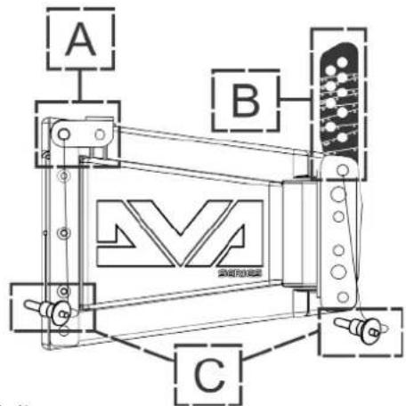
text_image
A B Cnatural_image
Technical line drawing of a mechanical assembly with no visible text or symbols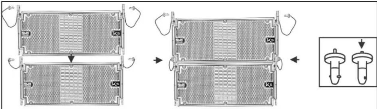
text_image
Technical diagram showing a multi-step assembly of a battery pack with internal compartments and labeled components (Ke)text_image
Technical diagram showing mechanical assembly with labeled components and a magnified detail view of the internal structure.DVA K5 Cod. 420120232 REV.1.1
text_image
DVA K5 QUICK CONFIGURATIONS SPEAKERS COUPLING STACK / FLOWN NUMBER OF CABINETS SET 1 or 2 A 3 or 4 B 5 or 6 C 7 or 8 D 9 or 10 E 11 or 12 F more than 12 G service HIGH FREQ. COMPENSATION STACK USE flat HF boost FLOWN USE DISTANCE (m) ANGLES SET from 0 to 20 from 0° to 4,5° from 6° to 15° from 0° to 4,5° from 6° to 15° from 0° to 4,5° from 6° to 15° more than 31 from 0° to 4,5° from 6° to 15° FLYBAR at 0°DVA K5 Cod. 420120232 REV.1.1
natural_image
Technical line drawings of three different mechanical or electrical components with no visible text or symbolsCONFIGURAZIONE STACKED SU SUBWOOFER TRAMITE FLY-BAR
natural_image
Technical line drawing of a multi-tiered electrical enclosure with mounting brackets and wiring (no text or symbols)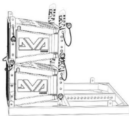
natural_image
Technical line drawing of a mechanical device with two stacked panels and mounting brackets (no text or symbols)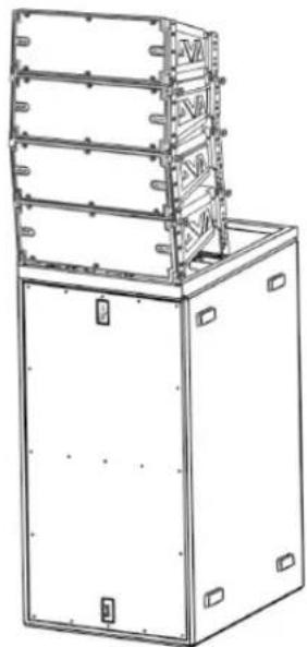
natural_image
Technical line drawing of a multi-tiered industrial machine or enclosure with mounting brackets (no text or symbols)DVA K5 Cod. 420120232 REV.1.1
text_image
Technical diagram showing installation of a multi-tiered server rack with labeled components and connectionsMaximum Load: 250 kg

natural_image
Technical line drawing of a multi-tiered electrical enclosure or rack unit with mounting flanges and control knobs (no text or symbols)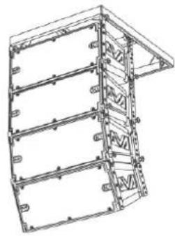
natural_image
Technical line drawing of a structural frame or panel assembly (no text or symbols)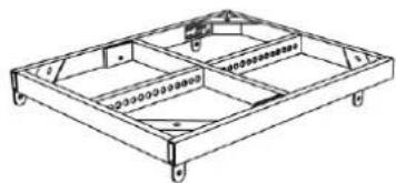
natural_image
Technical line drawing of a rectangular frame structure with internal compartments and mounting holes (no text or symbols)DRK-10
Maximum Load: 1300 kg Depending on pick point position

text_image
1200 kg (12 kN) 1300 kg (13 kN) 1000 kg (10 kN) 750 kg (7,5 kN) 2 3 4 5 6 7 8 9 10 11 12 13 14 15 16 17 18 19 20 21 22DRK-20
Maximum Load: 1000 kg In all cursor positions

text_image
10000 kg (10 kN) The system must be assembled by qualified person only!DRK-20M
CONFIGURAZIONE FLOWN O STACKED CON SUPPORTI LATERALI
natural_image
Technical line drawing of a multi-tiered industrial enclosure or storage unit with mounting holes and structural brackets (no text or symbols)
text_image
Diagram showing four different musical instrument positions with labeled parts and rhythmic markings
natural_image
Technical line drawing of a multi-level industrial or electrical cabinet with mounting holes and structural beams (no text or symbols)DVA K5 Cod. 420120232 REV.1.1
INSTALLAZIONE CON STAFFA A MURO
natural_image
Technical line drawing of a mechanical assembly with no visible text or symbolsUTILIZZO DI UN SOLLEVATORE DRL-45
POWER SUPPLY CONNECTION AND LINKING 36
INPUT CONNECTION AND EXTENSION 37
CONFIGURATION AND OPTIMISATION WITH DSP IN LINE-ARRAY.... 39
STACKED 40
FLOWN 40
3. INSTALLATION EXAMPLES 41
4. FIRMWARE UPDATES.... 44
5. TROUBLESHOOTING 45
6. TECHNICAL SPECIFICATIONS DVA K5 46
GENERAL 46
ACOUSTIC DATA 46
AMPLIFIER 46
PROCESSOR 47
USER INTERFACE 47
INPUTS AND OUTPUTS.... 47
POWER SUPPLY SPECIFICATIONS.... 47
DIMENSIONS 48
1. GENERAL INFORMATION
WELCOME!
Thank you for purchasing a product designed and developed in Italy by dBTechnologies! This 3-way active line-array module is the result of years of experience and innovation on speakers, with the use of cutting-edge solutions in the field of acoustics, electronics and research on materials.
PRELIMINARY OVERVIEW
The DVA K5 active line-array module is a 3-way speaker designed by building upon the innovation and professional quality of the DVA series. The 2 1" compression drivers (voice coil: 1.4"), 1 6.5" mid-range (voice coil: 2"), 1 8" woofer (voice coil: 2.5") are housed in a polypropylene cabinet, reinforced by a metal frame optimising its sound performance. The DSP, controlling the next-generation amplifier DIGIPRO G3, allows to easily and accurately configure the line-array sound behaviour according to: number of modules, angles of installation between the K5 modules, distance between line-array and audience. When coupled with the new DVA KS series subwoofers, finally, the module can meet all professional needs, in any context and installation.
The main features of K5 are:
- powerful and noiseless amplification section, thanks to the new DIGIPRO G3 D-class amplifier, requiring no active ventilation
- SPL (peak) of 129 dB
- high-quality transducers, sound design optimised for line-array use, full-range frequency response for professional use
- equipped as standard with pins and built-in brackets, pre-drilled and graduated, for easy, accurate and ready assembly/disassembly in a line-array configuration
- quick and accurate DSP configuration through 2 rotary encoders, optimising coupling and high frequency compensation
- Easy to handle and transport
- Lightweight, thanks to the polypropylene box and to the use of neodymium magnet components.
USER REFERENCES
To get the most from your DVA K5 we recommend that you:
- thoroughly read the quick start user manual you will find in the package and this manual, and keep it throughout the product life.
- register the product on the site http://www.dbtechnologies.com, in the "SUPPORT" section
- keep the proof of purchase and the WARRANTY (User manual "section 2").
DVA K5 Code 420120232 REV.1.1
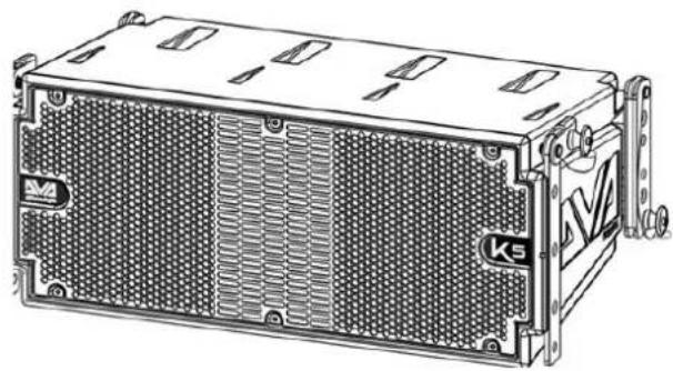
MECHANICAL AND ACOUSTIC CHARACTERISTICS
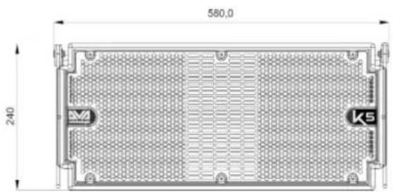
DIMENSIONS
DVA K5 only weighs 14.7 kg (32,41 lbs), and thanks to its small dimensions - 580 x 240 x 327 mm - it can be handled and transported easily.
The reinforced polypropylene cabinet has a metal inner frame, preventing unwanted resonances and vibrations. The built-in brackets and the standard pins are ready to use and allow to quickly install, in the proper arrangement, a line-array having the desired characteristics.
ACOUSTIC COVERAGE
The acoustic coverage, for reference purposes, of a single module, as shown in the figure, is of 100 x 15°. The actual coverage depends on the use of multiple modules in a line-array arrangement. We recommend that you design it with the help of the free software dBTechologies Composer.
ACCESSORIES
The following items are available as optional, for system installation, transport and protection:
• DRK-10 and DRK-20 fly-bars
- DRK-HK hook, to be used in conjunction with DRK-20
• DRK-20M motor-driven fly-bar
- SRK-10 installation kit (for installation with DVA KS10 subwoofer only)
- Bracket DWB-3 for wall installation and DSA-4 for floor or pedestal support installation.
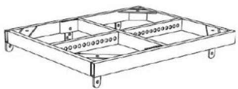
• Trolley allowing to transport 1 to 6 DT-6 modules
• Flight case containing 1 to 4 DF-4 modules
• Built-in flight case with trolley, housing and allowing to transport up to 4 DTF-4 modules
• Lifting equipment for hanging speakers DRL-45
• Extension cables DCK-15, DPC-15, DAC 15, DPC-1000M, cable kit DCK-15, DCK-45 and DCK-45 TypeB
text_image
580.0 240 M K5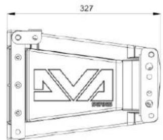
text_image
327 M 新安电极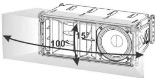
text_image
100° 15° 4The figure below shows a sample DRK-10 fly-bar and the fly-bar in question installed on a DT-6 trolley, for transport purposes only.
natural_image
Technical line drawing of a rectangular frame with internal compartments and mounting holes (no text or symbols)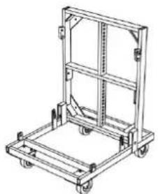
natural_image
Line drawing of a mechanical cart with wheels and frame structure (no text or symbols)For any further information, please refer to the site www.dbtechnologies.com and to the relevant manuals of each individual accessory.
DVA K5 Code 420120232 REV.1.1
CHARACTERISTICS OF THE AMPLIFICATION AND CONTROL SECTION
The D-class next generation amplifier DIGIPRO G3 features a power supply section with a particularly efficient auto-range function. The system is noiseless, as it doesn't require a ventilation system. The system is controlled by a powerful DSP allowing to readily and quickly configure the line-array in any usage context
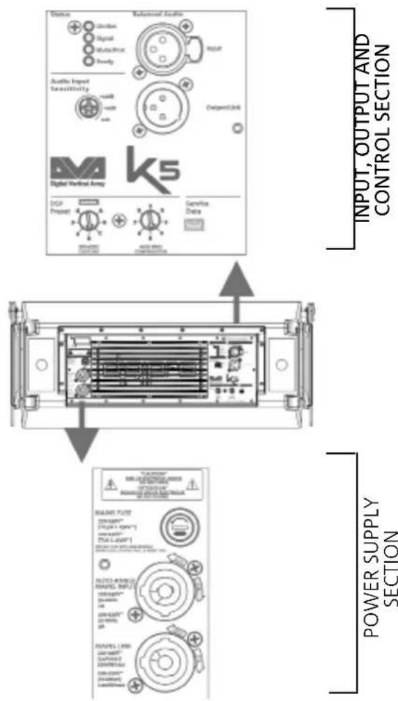
The DIGIPRO G3 panel consists of:
- Input Output and Control section
• Power supply section

ATTENTION!
- Protect the module from humidity.
- Never try to open the amplifier.
- In case of malfunction, immediately cut off the power supply, by disconnecting the module from the mains, then contact an authorised repairman.
text_image
Status Citation Signal Radio/Photo Supply Audio Input Tensitivity USB USB USB Output Unit Digital Audio Array DSG Present Service Data POWER SUPPLY SECTION INPUT, OUTPUT AND CONTROL SECTION SAMS FUT2 DINAMOS™ PTGA1-100P-1 Power Supply SAMS FUT2 DINAMOS™ PTGA1-100P-1 OUTPUT AND CONTROL SECTION FUT2-AMOSO MAPS INPUT DINAMOS™ PTGA1-100P-1 OUTPUT AND CONTROL SECTION MAPS LPRN DINAMOS™ PTGA1-100P-1 OUTPUT AND CONTROL SECTIONDVA K5 Code 420120232 REV.1.1
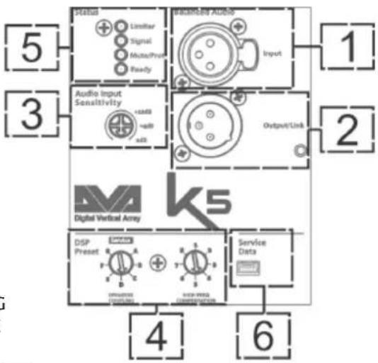
INPUT OUTPUT AND CONTROL SECTION
1. BALANCED AUDIO INPUT
Audio input for a cable equipped with a balanced XLR connector.
2. LINK AUDIO OUTPUT
Balanced XLR output, allowing to send the input audio signal to another amplified speaker.
3. AUDIO INPUT SENSITIVITY
It allows to vary the input sensitivity. Before turning on the unit, make sure that the Audio Input Sensitivity is turned to 0 dB.
- DSP CONTROL ROTARY ENCODERS FOR IN LINE-ARRAY SETTING The "SPEAKER COUPLING" rotary encoder and the "HIGH FREQUE COMPENSATION" rotary encoder allow to optimise the sound behaviour of the K5 modules configured in a line-array. Also refer to paragraph "IN LINE-ARRAY CONFIGURATION AND OPTIMISATION".
5. LEDs (Limiter, Signal, Mute/Prot, Ready)
During normal speaker operation with audio input signal, the Ready LED is steadily on, the Signal LED blinks indicating the signal presence.
6. "SERVICE DATA" USB PORT
The type B mini-USB B port allows to update the product firmware. For further information, please refer to the Web site (see DOWNLOADS section and )
flowchart
graph TD
    A["Digital Vertical Array"] --> B["Service Data"]
    A --> C["DSP Preset"]
    A --> D["Audio Input Sensitivity"]
    A --> E["Output/Link"]
    A --> F["Signal"]
    A --> G["Linearity"]
    A --> H["Noise Ratio"]
    A --> I["Control Signals"]
    A --> J["Output/Link"]
    A --> K["Linearity"]
    A --> L["Noise Ratio"]
    A --> M["Control Signals"]
    A --> N["Output/Link"]
    A --> O["Linearity"]
    A --> P["Linearity"]
    A --> Q["Linearity"]
    A --> R["Linearity"]
    A --> S["Linearity"]
    A --> T["Linearity"]
    A --> U["Linearity"]
    A --> V["Linearity"]
    A --> W["Linearity"]
    A --> X["Linearity"]
    A --> Y["Linearity"]
    A --> Z["Linearity"]
    A --> AA["Linearity"]
    A --> AB["Linearity"]
    A --> AC["Linearity"]
    A --> AD["Linearity"]
    A --> AE["Linearity"]
    A --> AF["Linearity"]
    A --> AG["Linearity"]
    A --> AH["Linearity"]
    A --> AI["Linearity"]
    A --> AJ["Linearity"]
    A --> AK["Linearity"]
    A --> AL["Linearity"]
    A --> AM["Linearity"]
    A --> AN["Linearity"]
    A --> AO["Linearity"]
    A --> AP["Linearity"]
    A --> AQ["Linearity"]
    A --> AR["Linearity"]
    A --> AS["Linearity"]
    A --> AT["Linearity"]
    A --> AU["Linearity"]
    A --> AV["Linearity"]
    A --> AW["Linearity"]
    A --> AX["Linearity"]
    A --> AY["Linearity"]
    A --> AZ["Linearity"]
    A --> BA["Linearity"]
| LED TYPE | SPEAKER SWITCH-ON | NORMAL OPERATION | GENERIC WARNING | STOP DUE TO SPEAKER MALFUNCTION |
| LIMITER OFF | TURNED OFF, | TURNS ON ONLY IN THE EVENT OF INTERVENTION | TEMPORARY BLINKING | ONGOING CYCLIC BLINKING |
| SIGNAL OFF | BLINKING WITH | SIGNAL | NORMAL INPUT AUDIO INDICATION | OFF |
| MUTE/ PROT | ON FOR A FEW SECONDS | OFF TEMPORARY | BLINKING | STEADILY ON |
| READY OFF | STEADILY ON S | STEADILY ON OFF |
DVA K5 Code 420120232 REV.1.1
LEDs table
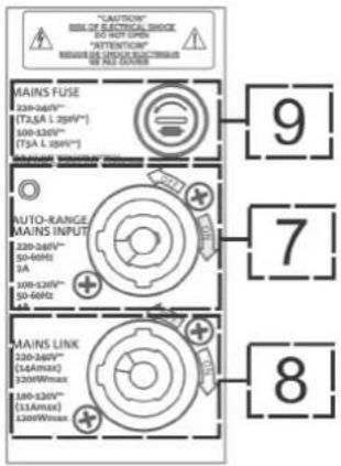
POWER SUPPLY SECTION
7. "AUTO-RANGE MAINS INPUT" POWER SUPPLY INPUT
Power supply input for cable equipped with NEUTRIK® powerCON® connector.
8. "MAINS LINK" POWER SUPPLY LINKING OUTPUT
Output allowing to extend the power supply to a second module through a cable equipped with a NEUTRIK® powerCON connector.
9. "MAINS FUSE" PROTECTION FUSE
Mains fuse

ATTENTION!
- The speaker is supplied with a mounted fuse for operation within the 220-240V\~ range. If you need to operate in the 100-120V\~ voltage range:
- Disconnect all connections, including the power supply.
- Wait 5 minutes.
-
Replace the fuse with the one provided in the package for the 100-120V\~ range.
-
Only use cables equipped with high-quality genuine Neutrik® connectors.
- Never use the speaker for a prolonged time while the limiter LED is on or blinking, indicating the equipment is running under excessive stress conditions
text_image
"CAUTION" RISK OF ELECTRICAL SWITCH DO NOT OPEN "ATTENTION" REQUIRE DE CONDUIT ELECTRICAL WE GET COOKING MAINS FUSE 220-240V~ (T2A L 250V*) 100-120V~ (T3A L 250V*) AUTO-RANGE MAINS INPUT 220-240V~ 50-60Hz 9A 100-120V~ 50-60Hz 9A MAINS LINK 220-240V~ (14Amax) 120V/Max 180-120V~ (13Amax) 120V/Max 9 7 8DVA K5 Code 420120232 REV.1.1
2. FIRST SWITCH-ON
PACKAGE CONTENTS
The DVA K5 package includes:
- DVA K5
- Quick start and warranty/safety-related documents
- Fuse to be installed if the system is to operate within the 100-120V range
PRELIMINARY OPERATIONS
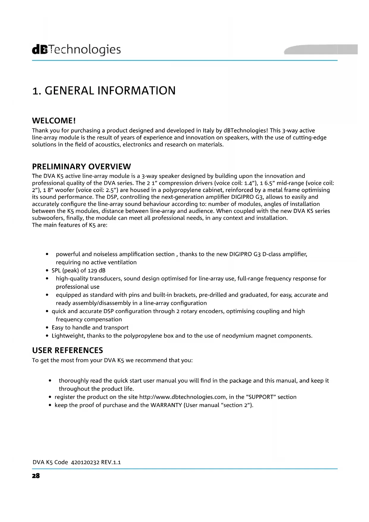
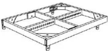
The DVA K5 built-in mechanical components installed on each speaker side are:
A - FRONT BRACKET
B - PRE-DRILLED AND GRADUATED REAR BRACKET
C - QUICK COUPLING/RELEASE PIN
natural_image
Technical line drawing of a rectangular electronic device with heat sinks and mounting brackets (no text or symbols)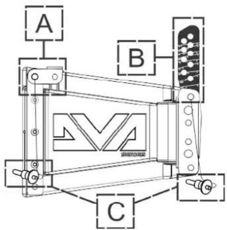
text_image
A B CBefore installing the equipment, when opening the package remember to:
- Remove the plastic protections from the side pins
- Remove the bag containing the fuse
DVA K5 Code 420120232 REV.1.1
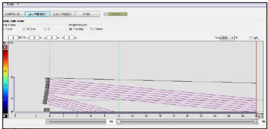
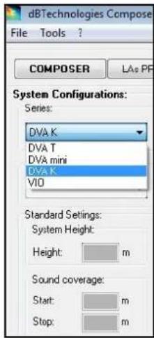
USING DBTECHNOLOGIES COMPOSER
The software dBTechnologies Composer, which can be downloaded for free from www.dbtechnologies.com, is a tool allowing users to properly design their audio system, recommended for all the equipment belonging to the DVA K series.
It proposes the optimum solution for the selected areas, specifying the line-array module angle required to obtain the proposed coverage.
It also allows to effectively check the safe installation of the line-array modules, by simulating the static behaviour of the fly-bars.
For further information please refer to the DOWNLOADS section of www.dbtechnologies.com.
text_image
Tools COMPODER LAa PREDICT SUBa PREDICT PRINT COMPUTER View Side View Top Spane Type Input J People Features Standing Named 0 MCPX x 0 = y 0 = d 0 = Temp: 2000 °/h SP [cm] 10 1 30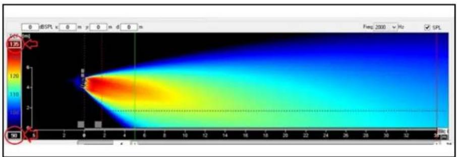
heatmap
| Time (s) | Value | | -------- | ----- | | 0 | 1.25 | | 150 | 1.25 |

text_image
dBTechologies Compose File Tools ? COMPOSER LAs PF System Configurations: Series: DVA K DVA T DVA mini DVA K VIO Standard Settings: System Height: Height: m Sound coverage: Start: m Stop: m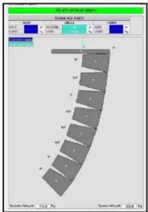
text_image
40.47% of local steel PUMA PUC ROOTS SIZE: 100000000000000000000000000000000000000000000000000000000000000000000 MILK: 5.845 MILK: 5.845 MILK: 5.845 MILK: 5.845 MILK: 5.845 MILK: 5.845 MILK: 5.845 MILK: 5.845 MILK: 5.845 MILK: 5.845DVA K5 Code 420120232 REV.1.1
INSTALLING DVA K5 IN A LINE-ARRAY CONFIGURATION
After defining the final line-array characteristics, and the required angle in particular, you can proceed with the installation. Please check that Audio Input Sensitivity is set on 0 dB (common usage).
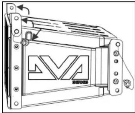
- Raise the front brackets of the lower module after extracting the pins from the cabinet.
- Insert the upper module, aligning the brackets on the front side as shown.
- Lock the 2 modules on the front side by inserting the relevant quick-release pins. The pin pressing/release movement is shown in the figure below.
natural_image
Technical line drawing of a mechanical component with no visible text or symbols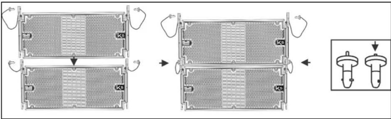
text_image
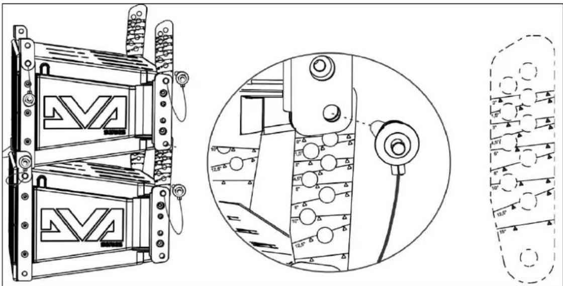
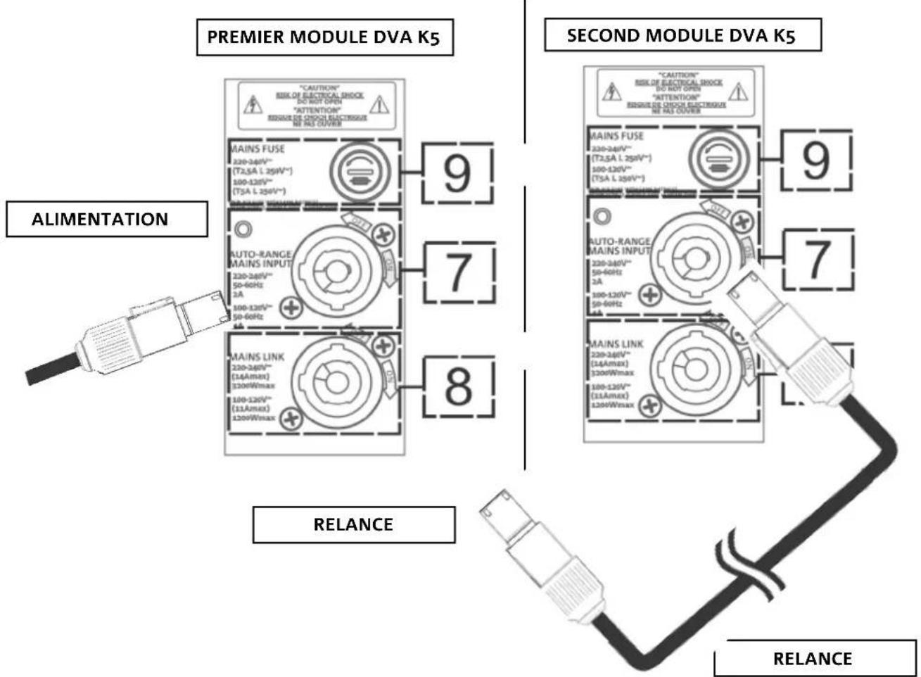
Technical diagram showing assembly steps of a mechanical component with labeled parts (Ks) and an inset view of the final component.- While holding the upper module raised, raise the brackets on the rear side of the lower cabinet.
- Insert the graduated rear brackets into the specified seats, at the desired angle. Fix them by inserting the relevant pins. The angle between the 2 installed modules is indicated by a line appearing just below the configuration. In the figure below, for example, the angle is 0^ . Inclination can be set in steps of 1.5^ in the 0^ - 6^ range, in steps of 2^ in the 6^ - 10^ range and in steps of 2.5^ in the 10^ to 15^ range.
text_image
Technical diagram showing mechanical assembly with labeled components and angular measurementsDVA K5 Code 420120232 REV.1.1
POWER SUPPLY CONNECTION AND LINKING
text_image
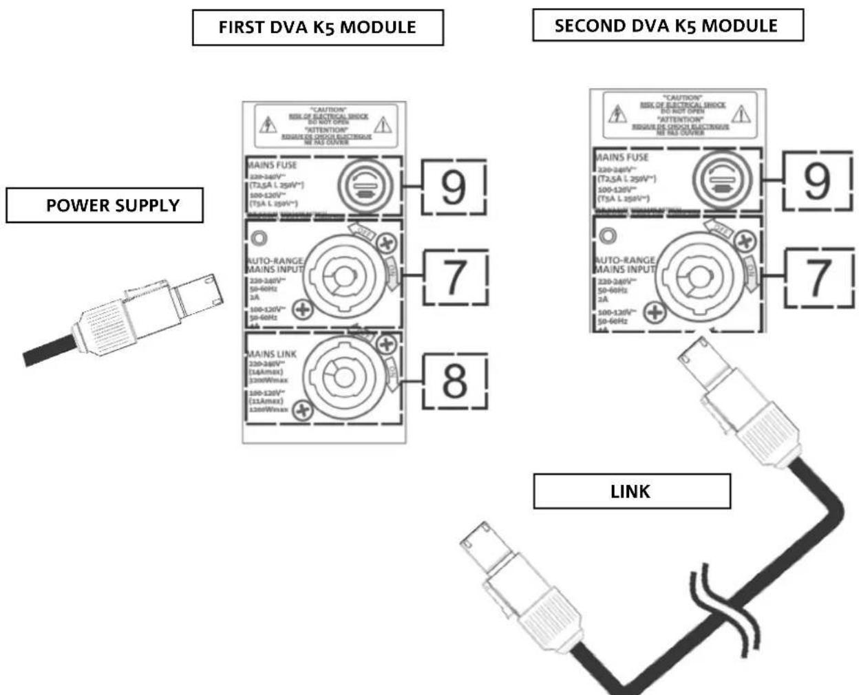
FIRST DVA K5 MODULE SECOND DVA K5 MODULE POWER SUPPLY LINK- Connect the first module power supply to AUTO-RANGE MAINS INPUT (7). For this purpose, use a cable equipped with a powerCON connector (not included in the supply).
- Extend the power supply from the first to the second module, by connecting the MAINS LINK OUTPUT (8) to the AUTO-RANGE MAINS INPUT (7), as shown in the figure.
- Repeat the operation between the second and the third module, and so on, until all line-array modules are connected (check the maximum number of power supply links in Technical Specifications).

ATTENTION!
- The amplifier nameplate of a DVA K5 module specifies the nominal maximum and total current (and power) value of a multiple module system with extension connections.
- The cables must be properly sized and design, installation and system testing should exclusively be performed by qualified personnel. AEB Industriale accepts no responsibility in case of use of cables which are unsuitable, non-certified, non-compatible with the correct system sizing and the regulations in force in the country of use.
DVA K5 Code 420120232 REV.1.1
INPUT CONNECTION AND EXTENSION
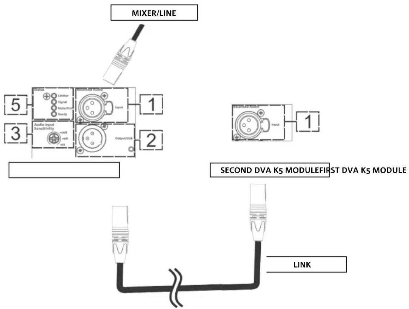
text_image
MIXER/LINE 5 3 Audio Input Sensitivity +800E mA Output/Link 1 2 SECOND DVA K5 MODULEFIRST DVA K5 MODULE LINK- Connect the cable from MIXER/LINE to the BALANCED AUDIO (1) input of the first line array module. For this purpose, use a cable equipped with an XLR connector (not included in the supply). For further information about the cables that are available please refer to the picture at p. 37.
- Extend the signal between the first and the second module. To this purpose connect the OUTPUT/LINK (2) output to the BALANCED AUDIO (1) input of the second module.
- Repeat the operation between the second and the third module, and so on, until all line-array modules are connected.

ATTENTION!
- Only use cables equipped with Neutrik® connectors
- Replace any damaged cables, to avoid malfunctions and poor sound quality.
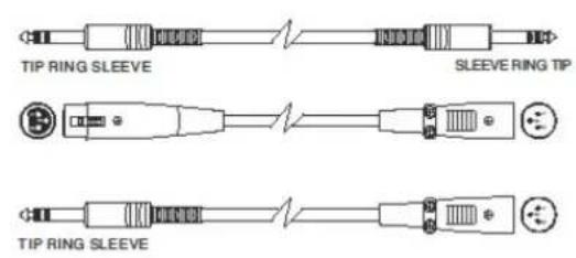
• Balanced
text_image
TIP RING SLEEVE SLEEVE RING TIP TIP RING SLEEVE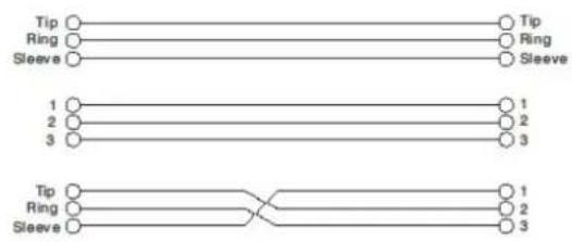
flowchart
graph TD
    A["Tip"] --> B["Ring"]
    B --> C["Sleeve"]
    D["Tip"] --> E["Ring"]
    E --> F["Sleeve"]
    G["1"] --> H["2"]
    H --> I["3"]
    J["1"] --> K["2"]
    K --> L["3"]
    M["Tip"] --> N["Ring"]
    N --> O["Sleeve"]
    P["1"] --> Q["2"]
    Q --> R["3"]
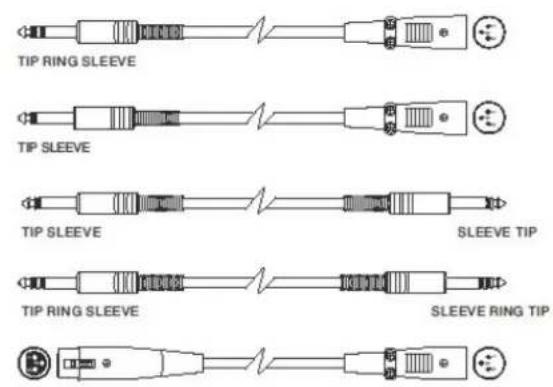
- Unbalanced
text_image
TIP RING SLEEVE TIP SLEEVE TIP SLEEVE SLEEVE TIP TIP RING SLEEVE SLEEVE RING TIP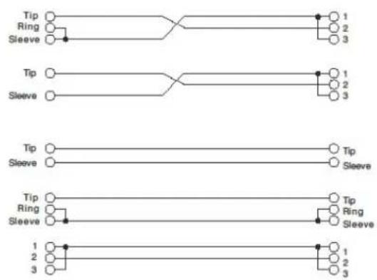
flowchart
graph TD
    A["Tip"] --> B["Ring"]
    B --> C["Sleeve"]
    D["Tip"] --> E["Sleeve"]
    F["Tip"] --> G["Sleeve"]
    H["Tip"] --> I["Sleeve"]
    J["1"] --> K["2"]
    L["3"] --> M["3"]
    N["1"] --> O["2"]
    P["3"] --> Q["3"]
CONFIGURATION AND OPTIMISATION WITH DSP IN LINE-ARRAY
The use of a line-array provides multiple benefits in various contexts; in particular:
- Homogeneous SPL along the speaker front direction; the effect is particularly noticeable over medium to long distances
- directive sound behaviour, allowing to accurately focus the sound on the audience, avoiding unnecessary dispersions in areas where acoustic coverage is not required
• The line-array optimisation takes into account the system behaviour with respect to the frequency: - as distance from the line-array increases, air attenuation increases as well. This particularly applies to high frequencies.
• as the angle of the line-array components increases decreases mid-frequency phase coupling
• as the number of line-array modules low frequencies add together in an acoustically coherent fashion
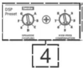
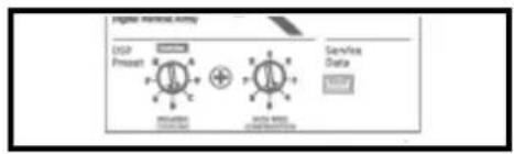
The DSP-managed control functions allow to optimise the line-array sound configuration of the DVA K5 modules. The user interface is simple and intuitive. It includes two rotary encoders installed in the “DSP Preset” (4) section and the reference label shown below:
- Turn the "SPEAKER COUPLING" rotary encoder to set the number of modules included in the line array. This rotary encoder affects the low frequencies and must be turned to the following position:
• A - 1 to 2 speakers
• B - 2 to 4 speakers
• C - 5 to 6 speakers
• D - 7 to 8 speakers
• E - 9 to 10 speakers
• F - 11 to 12 speakers
• G - 13 speakers and beyond
text_image
DSP Preset SPRING SPRING HIGH PRESS COMPREMUNICATIONS 4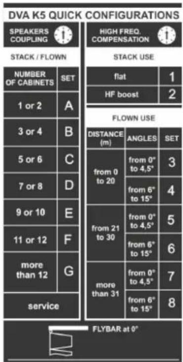
text_image
DVA K5 QUICK CONFIGURATIONS SPEAKERS COUPLING STACK / FLOWN NUMBER OF CABINETS SET 1 or 2 A 3 or 4 B 5 or 6 C 7 or 8 D 9 or 10 E 11 or 12 F more than 12 G service HIGH FREQ. COMPENSATION STACK USE flat HF boost 2 FLOWN USE DISTANCE (m) ANGLES SET from 0 to 20 from 0" to 4,5" from 6" to 15" from 21 to 30 from 0" to 4,5" from 6" to 15" from 0" to 4,5" from 6" to 15" more than 31 from 0" to 4,5" from 6" to 15" 8 FLYBAR at 0"- Turn the “HIGH FREQUENCY COMPENSATION” rotary encoder according to the type of installation and angle set in the line-array. This rotary encoder affects the medium to high frequency sections and must be turned to the following position:
STACKED
- 1 - installation in a stacked configuration (for example on subwoofer through the specially designed DRK-10 fly-bar), for an equalisation with no emphasis over the whole frequency range.
- 2 - installation in a stacked configuration (for example on subwoofer through the specially designed DRK-10 fly-bar), for an equalisation emphasising high frequencies
FLOWN
- 3 - installation in a flown configuration, with the audience 0-20 m away and an angle between each module ranging between 0° and 4.5°
- 4 - installation in a flown configuration, with the audience 0-20 m away and an angle between each module ranging between 6° and 15°
- 5 - installation in a flown configuration, with the audience 21-30 m away and an angle between each module ranging between 0^ and 4.5^
- 6 - installation in a flown configuration, with the audience 21-30 m away and an angle between each module ranging between 6° and 15°
- 7 - installation in a flown configuration, with the audience over 31 m away and an angle between each module ranging between 0° and 4.5°
- 8 - installation in a flown configuration, with the audience over 31m away and an angle between each module ranging between 6° and 15°
3. INSTALLATION EXAMPLES

ATTENTION!
- Never use the speaker handles, brackets or other components to hang the system!
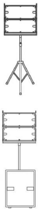
INSTALLATION ON TRIPOD STAND
DVA K5 can be installed on an optional standard tripod with a pole having a diameter of 35 mm. The DSA-4 accessory is required for this installation; you can mount up to 2 modules and the maximum permitted distance between the first element and the ground is 130 cm. DSA-4 allows a maximum inclination of ±5^ . For further information, please refer to the instructions of this accessory.
INSTALLATION ON SUBWOOFER WITH POLE
To install the modules on a subwoofer DVA KS10, DVA KS20, DVA S10DP or DVA S1518N you must use a pole having a diameter of 35 mm. For this type of installation, the distance between the speaker base and the floor must not exceed 85 cm, and you can mount up to 2 DVA K5 modules. To this purpose you need to use a DSA-4 accessory, and the downward inclination of the speakers must not exceed 5°.
INSTALLATION ON A FLAT SURFACE
DVA K5 can be installed on a flat surface, using the DRK-10/DRK-20 fly-bars (max 6 modules) and the DSA-4 (max. 3 modules) accessory For further information please refer to the relevant manuals.
natural_image
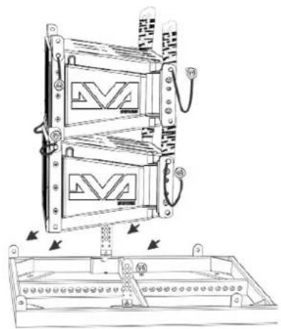
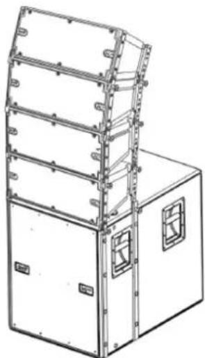
Technical line drawings of three different mechanical or electrical components with no visible text or symbolsSTACKED INSTALLATION ON SUBWOOFER THROUGH A FLY-BAR
Stacked modules can be directly installed on a subwoofer, using a DRK-10/DRK-20 fly-bar. For further information please refer to the relevant manuals.
text_image
Technical diagram of a multi-chamber electrical enclosure with labeled components and directional arrows indicating assembly or installation.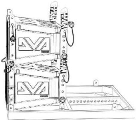
natural_image
Technical line drawing of a mechanical device with two stacked panels and a base panel (no text or symbols)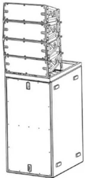
natural_image
Technical line drawing of a multi-tiered industrial machine or enclosure with mounting brackets (no text or symbols)DVA K5 Code 420120232 REV.1.1
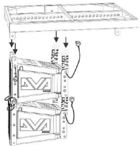
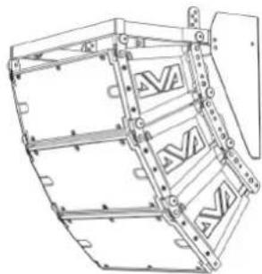
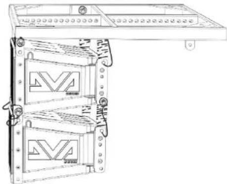
FLOWN INSTALLATION
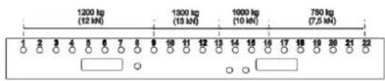
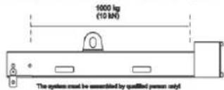
DVA K5 can be installed in a flown configuration, using the DRK-10 or DRK-20 (or DRK-20M) fly-bars. Proper installation and safety load limits can be verified with the help of dBTechologies Composer. For further information please refer to the safety labels and to the relevant instructions for the fly-bars (DRK-10: 250 kg max, DRK-20: 1300 kg max, depending on the connecting point, DRK-20M: 1000 kg max).
text_image
Technical diagram showing installation of a multi-chamber air vent with labeled components and connectionsMaximum Load: 250 kg

natural_image
Technical line drawing of a multi-tiered electronic device with mounting holes and internal panels (no text or symbols)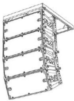
natural_image
Technical line drawing of a multi-level structural frame or enclosure (no text or symbols)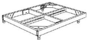
natural_image
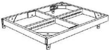
Technical line drawing of a rectangular frame structure with mounting holes and internal components (no text or symbols)DRK-10
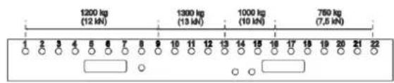
Maximum Load: 1300 kg Depending on pick point position
text_image
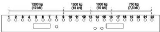
1200 kg (12 kN) 1300 kg (13 kN) 1000 kg (10 kN) 750 kg (7,5 kN) 2 3 4 5 6 7 8 9 10 11 12 13 14 15 16 17 18 19 20 21 22DRK-20
Maximum Load: 1000 kg In all cursor positions
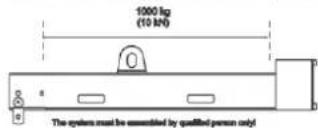
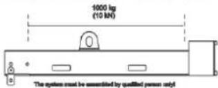
text_image
1000 kg (10 kN) The system must be assembled by qualified person only!DRK-20M
FLOWN OR STACKED INSTALLATION WITH SIDE SUPPORTS
DVA K5 can be directly mounted on a DVA KS10 subwoofer in a stacked configuration, or in a flown configuration under a DVA KS10, as shown in the figure, using the optional SRK-10 accessory.
natural_image
Technical line drawing of a multi-tiered industrial enclosure or storage unit with mounting holes and structural beams (no text or symbols)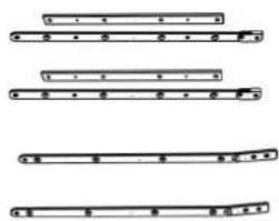
text_image
Diagram showing four different musical instrument positions with labeled parts and rhythmic markings
natural_image
Technical line drawing of a multi-level industrial enclosure or storage unit with mounting brackets and structural beams (no text or symbols)DVA K5 Code 420120232 REV.1.1
INSTALLATION WITH WALL BRACKET
DVA K5 can be wall-mounted, using the optional DWB 3 bracket. The further mechanical accessories required for bracket installation are not included.
natural_image
Technical line drawing of a mechanical assembly with no visible text or symbolsUSE OF DRL-45 LIFTING EQUIPMENT
DVA K5 can be lifted using DRL-45 lifting equipment. The line-array to be lifted must use a properly installed DRK-10 fly-bar.

ATTENTION!
For safe use of accessories, periodically check their functionality and integrity before using them.
Accessories must be used by qualified personnel only! Make sure the installation is stable and safe, to avoid any hazard to people, animals and/or property. The user must verify the binding safety regulations and laws in force in the Country where the product is being used. When installing the product follow the instructions provided herein.
4. FIRMWARE UPDATES
IT IS very important to keep product firmware updated to the latest version to ensure full performance. Please check site http://www.dbtechnologies.com for updates under section "DOWNLOADS" periodically.
text_image
Digital Microarray Array DSP Processor Service Data DIP DIP DIP DIP DIP DIP DIP DIP DIP DIP DIP DIP DIP DIP DIP DIP DIP DIP DIP DIP DIP DIP DIP DIP DIP DIP DIP DIP DIP DIP DIP DIP DIP DIP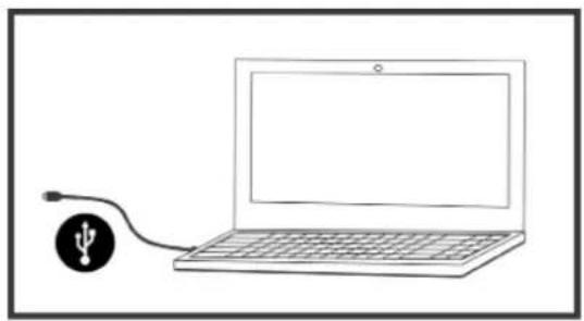
natural_image
Simple line drawing of a laptop connected to a USB symbol (no text or labels)- Download USB BURNER MANAGER from section "SOFTWARE & CONTROLLER" of the dBTechologies site.
- Download the .zip file with the last firmware from section "DOWNLOADS" for your product
- Connect the product to the PC by means of a USB cable (not supplied) featuring the right connector detail is contained in section FEATURES OF THE AMPLIFIER AND CONTROL SECTIONS
- In the top right corner of the USB BURNER MANAGER screen, select "File Opening".
- Select the firmware file you have downloaded previously (ensure that it is suitable for your operating system).
- Follow the on-screen instructions.
- Click UPDATE.
DVA K5 Code 420120232 REV.1.1
5. TROUBLESHOOTING
The speaker doesn't turn on:
- Check that the power supply upstream of the system is working properly
- Check that the power cord is properly plugged
- Check that the ON/OFF selector is turned to "I".
The speaker turns on but it doesn't output any sound:
- Check that the input connections of the main audio signal and of the auxiliary one, if any, have been performed properly
- Check that the cables in use are not damaged
- Check that the mixer or the audio source are on and that they clearly indicate the presence of an output signal to the speaker.
- Check that the level of the main audio volume and of the auxiliary one, if any, are set to an appropriate value.
The speaker outputs a distorted sound:
- Check that the Audio Input Sensitivity rotary encoder is set on the correct value (0 dB). It should be noted that if the LIMITER LED is on, it indicates the speaker is operating under distorting conditions.
- Check that the cables in use are not damaged; should that be the case, replace them (a damaged cable may result in a signal loss or alteration).
- Check that the LINE-MIC switch matches the actual input connection.
- Check the settings of the rotary encoder DSP preset affecting the output frequency response. To this purpose please refer to section FIRST SWITCH-ON.
6. TECHNICAL SPECIFICATIONS DVA K5
GENERAL
| Type: | 3-way active line-array module |
ACOUSTIC DATA
| Frequency response [±3 dB]: 70 - 19000 Hz | |
| Max SPL: 129 dB | |
| HF: 2x 1” (Voice coil:1.4”) | |
| Type HF: | Ceramic |
| MF: | 1x 6.5” (Voice coil: 2”) |
| LF: | 1x 8” (Voice coil: 2.5”) |
| Type MF- LF: | Neodymium |
| Crossover frequency: | 340 Hz (Low/Mid), 1800 Hz (Mid/High) |
| Directivity (HxV): | 100°x15° (single module) |
AMPLIFIER
| Type: Digipro® G3 | |
| Amplification class: D class | |
| Amplification power (Peak) 1000 W | |
| Amplification power(RMS): 500 W | |
| Power supply: SMPS with PSU Auto-range | |
| Power supply connector: (PowerCON In/Link) | |
| Cooling technique: Convection | |
| Controls: | Sensitivity control, 2 rotary encoders with 8 positions (Coupling, Compensation) |
DVA K5 Code 420120232 REV.1.1
PROCESSOR
| Internal controller: DSP 25/56 bit/48 kHz | |
| Advanced functions: FIR filters | |
| Limiter: Peak, Thermal |
USER INTERFACE
| Controls: Sensitivity control, 2 8-position rotaries |
| Led Limiter, Signal, Mute/prot, Ready |
INPUTS AND OUTPUTS
| Power supply inputs and links: PowerCON In/Link |
| Audio input: 1x XLR IN, balanced |
| USB: 1x USB MINI, type B |
| Audio output: 1x XLR link OUT, balanced |
POWER SUPPLY SPECIFICATIONS
| Absorption at 1/8 of full power in audio average use conditions (*): | 0,72 A / 76 W (220-240V~) - 1,22 A / 70 W (100-120V~) |
| Absorption at 1/3 of full power in audio maximum use conditions (**): | 1,25 A / 140 W (220-240V~) - 2,12 A / 144 W (100-120V~) |
| Nominal full power absorption (***): | 2 A (220-240V~) - 4 A (100-120V~) |
| Draw with speaker turned on without signal (idle): : | 19 W |
| Inrush current: | 18.3 A |
| Total current and power allowed in daisy-chain configuration (***): | 14 A / 3200 W max (220-240V~) - 11 A / 1200 W max (100-120V~) |
* INSTALLER NOTES: The values refer to 1/8 of full power, in average operating conditions (music program with infrequent or no clipping). It is recommended to consider them the minimum sizing values for any type of configuration.
** INSTALLER NOTES: The values refer to 1/3 of full power, in heavy operating conditions (music program with frequent clipping or activation of the limiter). We recommend sizing according to these values in case of professional installations and tours.
*** Values obtained using a continuous sinusoidal signal
DVA K5 Code 420120232 REV.1.1
DIMENSIONS
| Material: metal-reinforced polypropylene | |
| Grid: NC machining | |
| Handles built-in | |
| Connecting points: built into the cabinet | |
| Direct installation on pole: No, with accessories only | |
| Width: 580 mm (22.83 inch.) | |
| Height: 240 mm (9.45 inch.) | |
| Depth: 327 mm (12.87 inch.) | |
| Weight: 14,7 kg (32,41 lbs) |
The characteristics, specifications and appearance of the products are subject to change without warning. dBTechologies reserves the right to make any change or improvement to product design or manufacturing without undertaking any obligation to also change or improve the previously manufactured products.

text_image
ABA.E.B. Industriale Srl
Via Brodolini, 8
natural_image
Technical line drawing of a rectangular frame with internal compartments and mounting holes (no text or symbols)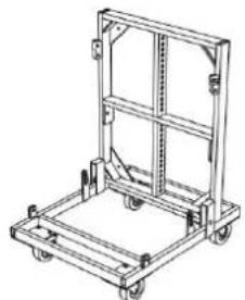
natural_image
Line drawing of a mechanical cart or pallet with wheels and frame structure (no text or symbols)natural_image
Technical line drawing of a rectangular electronic device with heat sinks and mounting brackets (no text or symbols)
text_image
A B Cnatural_image
Technical line drawing of a mechanical component with mounting flanges and a central logo (no readable text or symbols)
text_image
Technical diagram showing four stages of a mechanical component with labeled parts 'Ke' and an inset view of the final component.text_image
Technical diagram showing mechanical components with labeled parts and a magnified view of the internal structure.DVA K5 REV. 1.1 Code 420120232REV. 1.1
text_image
DVA K5 QUICK CONFIGURATIONS SPEAKERS COUPLING STACK / FLOWN NUMBER OF CABINETS SET 1 or 2 A 3 or 4 B 5 or 6 C 7 or 8 D 9 or 10 E 11 or 12 F more than 12 G service HIGH FREQ. COMPENSATION STACK USE flat HF boost FLOWN USE DISTANCE (m) ANGLES SET from 0 to 20 from 0° to 4,5° from 6° to 15° from 21 to 30 from 0° to 4,5° from 6° to 15° from 0° to 4,5° more than 31 from 6° to 15° FLYBAR at 0°DVA K5 REV. 1.1 Code 420120232REV. 1.1
natural_image
Technical line drawings of three different electronic device configurations (no text or symbols)STACKED- INSTALLATION AUF SUBWOOFER MITTELS FLY-BAR
text_image
Technical diagram of a mechanical device with labeled components and directional arrows indicating assembly or assembly steps.
natural_image
Technical line drawing of a mechanical device with two stacked panels and mounting brackets (no text or symbols)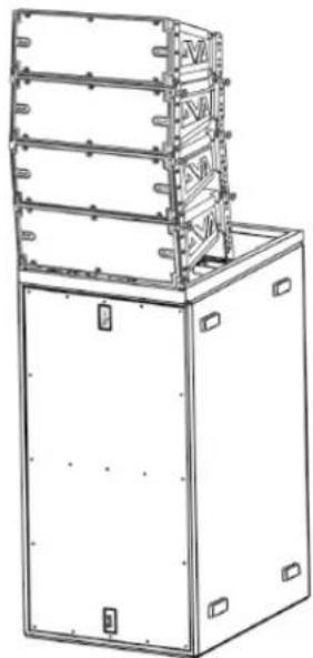
natural_image
Technical line drawing of a multi-tiered industrial machine or control unit (no text or symbols visible)DVA K5 REV. 1.1 Code 420120232REV. 1.1
FLOWN- INSTALLATION
text_image
Technical diagram showing assembly steps of a device with labeled components and directional arrows indicating assembly direction.Maximum Load: 250 kg
natural_image
Technical line drawing of a server rack unit with two panels and ventilation slots (no text or symbols)
natural_image
Technical line drawing of a multi-level structural frame or enclosure (no text or symbols)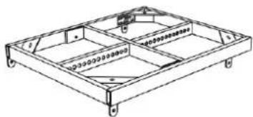
natural_image
Technical line drawing of a rectangular frame structure with internal compartments and mounting holes (no text or symbols)DRK-10
Maximum Load: 1300 kg Depending on pick point position

text_image
1200 kg (12 kN) 1300 kg (13 kN) 1000 kg (10 kN) 750 kg (7,5 kN) 2 3 4 5 6 7 8 9 10 11 12 13 14 15 16 17 18 19 20 21 22DRK-20
Maximum Load: 1000 kg In all cursor positions

text_image
10000 kg (10 kN) The system must be assembled by qualified person onlyDRK-20M
FLOWN- ODER STACKED- INSTALLATION MIT SEITLICHEN HALTERUNGEN
natural_image
Technical line drawing of a multi-tiered industrial enclosure or storage unit with mounting holes and ventilation grilles (no text or symbols)DVA K5 REV. 1.1 Code 420120232 REV. 1.1

natural_image
Four horizontal line segments with dots and brackets, no text or symbols present
natural_image
Technical line drawing of a multi-level industrial or mechanical cabinet with mounting holes and structural beams (no text or symbols)INSTALLATION MIT WANDBÜGEL
natural_image
Technical line drawing of a mechanical assembly with brackets and mounting holes (no text or symbols)natural_image
Simple line drawing of a laptop connected to a USB symbol (no text or labels)DONNÉES ACOUSTIQUES 91
AMPLIFICATEUR.... 91
PROCESSEUR 92
ENTRÉES ET SORTIES.... 92
SPÉCIFICATIONS D'ALIMENTATION.... 92
DIMENSIONS 93
DVA K5 REV. 1.1 Code 420120232REV. 1.1
1. INFORMATIONS GÉNÉRALES
BIENVENUE!
natural_image
Technical line drawing of a rectangular frame with internal compartments and mounting holes (no text or symbols)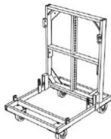
natural_image
Technical line drawing of a mechanical cart or pallet assembly (no text or symbols)natural_image
Technical line drawing of a rectangular electronic device with heat sinks and mounting brackets (no text or symbols)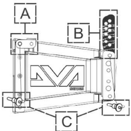
text_image
A B Cnatural_image
Technical line drawing of a mechanical assembly with no visible text or symbols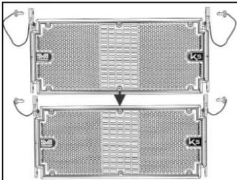
natural_image
Two identical views of a heat exchanger or cooling unit with internal grating and cooling fins, showing no text or symbols.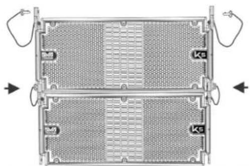
natural_image
Top-down view of a two-tiered electronic device casing with heat sinks and ventilation grilles (no text or symbols visible)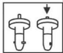
text_image
Technical diagram showing exploded and assembled views of a mechanical device with labeled components and angular measurements.DVA K5 REV. 1.1 Code 420120232REV. 1.1
BRANCHEMENT ET RELANCE DE L'ALIMENTATION
text_image
PREMIER MODULE DVA K5 ALIMENTATION SECOND MODULE DVA K5 RELANCE RELANCEtext_image
DVA K5 QUICK CONFIGURATIONS SPEAKERS COUPLING STACK / FLOWN NUMBER OF CABINETS SET 1 or 2 A 3 or 4 B 5 or 6 C 7 or 8 D 9 or 10 E 11 or 12 F more than 12 G service HIGH FREQ. COMPENSATION STACK USE flat HF boost 1 2 FLOWN USE DISTANCE (m) ANGLES SET from 0 to 20 from 0° to 4,5° from 6° to 15° from 21 to 30 from 0° to 4,5° from 6° to 15° from 0° to 4,5° from 6° to 15° more than 31 from 0° to 4,5° from 6° to 15° FLYBAR at 0°DVA K5 REV. 1.1 Code 420120232REV. 1.1
natural_image
Technical line drawings of three different electronic device configurations (no text or symbols)INSTALLATION STACKED SUR CAISSON DE BASSES AU MOYEN DE FLY-BAR
text_image
Technical diagram of a mechanical device with labeled components and directional arrows indicating assembly or assembly steps.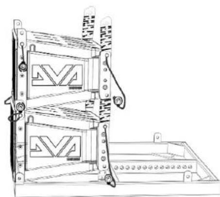
natural_image
Technical line drawing of a mechanical device with two stacked panels and mounting brackets (no text or symbols)
natural_image
Technical line drawing of a multi-tiered industrial machine or enclosure with mounting brackets (no text or symbols)DVA K5 REV. 1.1 Code 420120232REV. 1.1
INSTALLATION FLOWN
text_image
Technical diagram showing assembly steps of a device with labeled components and directional arrows indicating assembly direction.Maximum Load: 250 kg

natural_image
Technical line drawing of a server rack unit with two internal panels and ventilation slots (no text or symbols)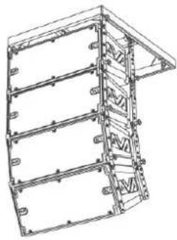
natural_image
Technical line drawing of a multi-level structural frame or enclosure (no text or symbols)Maximum Load: 1000 kg In all cursor positions
Maximum Load: 1300 kg Depending on pick point position
natural_image
Technical line drawing of a mechanical frame structure with mounting holes and internal compartments (no text or symbols)DRK-10
text_image
1200 kg (12 kN) 1300 kg (13 kN) 1000 kg (10 kN) 750 kg (7,5 kN) 1 2 3 4 5 6 7 8 9 10 11 12 13 14 15 16 17 18 19 20 21 22DRK-20
text_image
10000 kg (10 kN) The system must be assembled by qualified person onlyDRK-20M
INSTALLATION FLOWN OU STACKED AVEC SUPPORTS LATÉRAUX
natural_image
Technical line drawing of a multi-tiered industrial enclosure or storage unit with mounting holes and ventilation grilles (no text or symbols)
natural_image
Pure electrical circuit lines without any symbols
natural_image
Technical line drawing of a multi-level industrial or structural cabinet with mounting brackets and structural supports (no text or symbols)DVA K5 REV. 1.1 Code 420120232 REV. 1.1
INSTALLATION MURALE AVEC ÉTRIERS DE BLOCAGE
natural_image
Technical line drawing of a mechanical assembly with no visible text or symbolsnatural_image
Technical line drawing of a rectangular frame with internal compartments and mounting holes (no text or symbols)
natural_image
Line drawing of a mechanical cart with wheels and frame structure (no text or symbols)text_image
100° 15° Mnatural_image
Technical line drawing of a rectangular electronic device with heat sinks and mounting brackets (no text or symbols)
text_image
A B Ctext_image
Tools ? COMPOSER LA PREDICT SUB PREDICT PRINT MONDAY 2000 View Side View % Splice Input J People Feature Standing Swed 0 ACFL x 0 = y 0 = 0 = 0 = 0 Temp: 2000 + 4x SP 5 10 30
heatmap
| Time (s) | Temperature (°C) | | -------- | ---------------- | | 0 | 1.75 | | 10 | 1.00 |
text_image
dBTechologies Compose File Tools ? COMPOSER LAs PF System Configurations: Series: DVA K DVA T DVA mini DVA K VIO Standard Settings: System Height: Height: m Sound coverage: Start: m Stop: m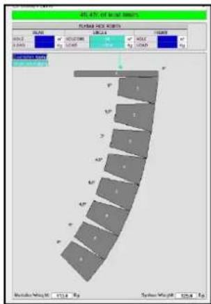
text_image
40.47% of material properties FORMER PROCESSED SCALE: 100% MOUNT: 0.245 SIZE: 100% RUM: 100% HOLD: 100% SPRING RED SPRING RED SPRING RED SPRING RED SPRING RED SPRING RED SPRING RED SPRING RED SPRING RED SPRING RED SPRING RED SPRING RED SPRING RED SPRING RED SPRING RED SPRING RED SPRING RED SPRING RED SPRING RED SPRING RED SPRING RED SPRING RED SPRING RED SPRING RED SPRING RED SPRING REDnatural_image
Technical line drawing of a mechanical assembly with no visible text or symbols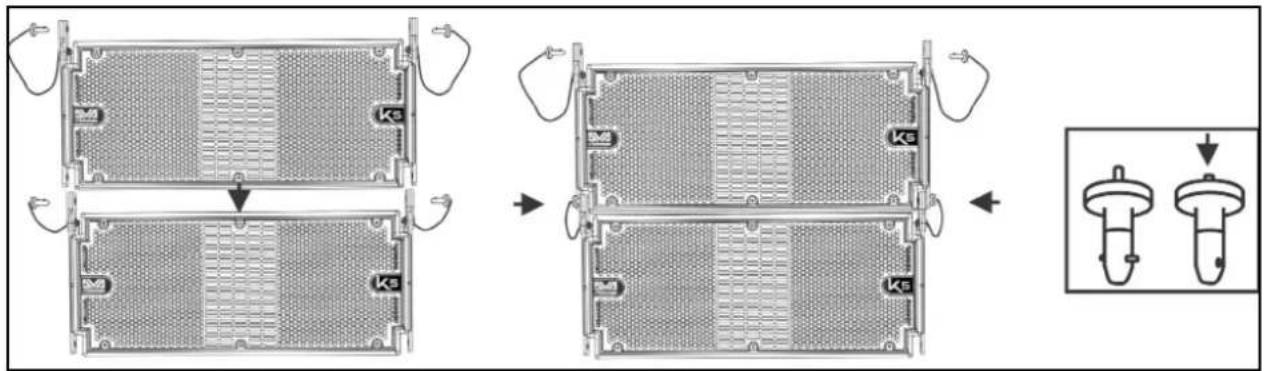
text_image
Technical diagram showing four stages of a mechanical component with labeled parts 'Ks', including a zoomed-in detail view.text_image
Technical diagram showing mechanical assembly with labeled components and a circular schematic view of the internal structure.DVA K5 REV. 1.1 Cód. 420120232 REV. 1.1
text_image
DVA K5 QUICK CONFIGURATIONS SPEAKERS COUPLING STACK / FLOWN NUMBER OF CABINETS SET 1 or 2 A 3 or 4 B 5 or 6 C 7 or 8 D 9 or 10 E 11 or 12 F more than 12 G service HIGH FREQ. COMPENSATION STACK USE flat HF boost FLOWN USE DISTANCE (m) ANGLES SET from 0 to 20 from 0° to 4,5° from 6° to 15° from 0° to 4,5° from 6° to 15° from 0° to 4,5° from 6° to 15° more than 31 from 0° to 4,5° from 6° to 15° FLYBAR at 0°DVA K5 REV. 1.1 Cód. 420120232 REV. 1.1
natural_image
Technical line drawings of three different mechanical or electrical components with no visible text or symbolstext_image
Technical diagram of a mechanical device with labeled components and directional arrows indicating assembly or assembly steps.
natural_image
Technical line drawing of a mechanical device with two stacked panels and mounting brackets (no text or symbols)
natural_image
Technical line drawing of a multi-tiered industrial machine or enclosure with mounting brackets (no text or symbols)DVA K5 REV. 1.1 Cód. 420120232 REV. 1.1
INSTALACIÓN FLOWN
text_image
Technical diagram showing assembly steps of a device with labeled components and directional arrows indicating assembly direction.Maximum Load: 250 kg

natural_image
Technical line drawing of a server rack unit with two panels and ventilation slots (no text or symbols)
natural_image
Technical line drawing of a multi-level structural frame or enclosure (no text or symbols)Maximum Load: 1000 kg In all cursor positions
Maximum Load: 1300 kg Depending on pick point position
natural_image
Technical line drawing of a rectangular frame structure with internal compartments and mounting holes (no text or symbols)DRK-10
text_image
1200 kg (12 kN) 1300 kg (13 kN) 1000 kg (10 kN) 750 kg (7,5 kN) 2 3 4 5 6 7 8 9 10 11 12 13 14 15 16 17 18 19 20 21 22DRK-20
text_image
10000 kg (10 kN) The system must be assembled by qualified person onlyDRK-20M
natural_image
Technical line drawing of a multi-tiered industrial enclosure or storage unit with mounting holes and ventilation grilles (no text or symbols)
natural_image
Four horizontal line segments with dots and brackets, no text or symbols present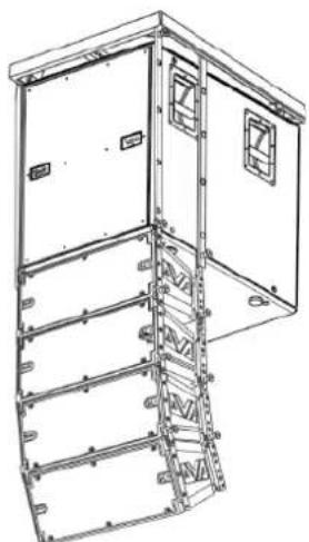
natural_image
Technical line drawing of a multi-level industrial or structural cabinet with mounting brackets and structural supports (no text or symbols)DVA K5 REV. 1.1 Cód. 420120232 REV. 1.1