
CONTROL 8 - Loudspeaker DB Technologies - Free user manual and instructions
Find the device manual for free CONTROL 8 DB Technologies in PDF.


| Product Type | Network Control Unit for RDNet System |
| Dimensions (W x H x D) | 482 mm x 44 mm x 182 mm (1U 19" rack) |
| Weight | 2 kg (4.4 lbs) |
| Power Supply | 100 – 240 V AC, 50-60 Hz, <15 W |
| Power Connector | Powercon |
| PC Connection | USB Type B (local) or Ethernet RJ45 (remote) |
| RDNet Ports | 8 x RJ45 (EtherCon) or 3-pole XLR (selectable) |
| Number of Subnets | 8 |
| Maximum Devices per Subnet | 32 |
| Total Devices Managed | Up to 256 |
| Network Protocol | EIA RS-485 (proprietary RDNet) |
| Max CAT5 Cable Length per Subnet | 900 m (2950 ft) |
| Front Panel Indicators | 8 x Subnet LEDs, 4 x Link LEDs, Error LED, Power LED |
| Controls | Power switch, SD card slot (not enabled) |
| Monitoring Features | Real-time VU-meter, temperature, limiter status, logistic status |
| Software | RDNet software for Windows (PC required) |
| Compatibility | dBTechnologies DVA Series and compatible devices |
| Chassis Material | Pre-galvanized steel, painted |
| Electromagnetic Classification | EN 55103 E3 (or lower E2, E1), Class A CISPR 32 |
| FCC | Part 15 Class A digital device |
Frequently Asked Questions - CONTROL 8 DB Technologies
User questions about CONTROL 8 DB Technologies
0 question about this device. Answer the ones you know or ask your own.
Ask a new question about this device
Download the instructions for your Loudspeaker in PDF format for free! Find your manual CONTROL 8 - DB Technologies and take your electronic device back in hand. On this page are published all the documents necessary for the use of your device. CONTROL 8 by DB Technologies.
USER MANUAL CONTROL 8 DB Technologies
USER MANUAL - Section 1
This device can be used on a stand or installed in a standard 19" rack.
The overall dimensions consist of a single unit; fastening is performed by 4 screws to be inserted into slots located on side flaps.
DESCRIPTION
RDNet Control 8 is an hardware interface to connect diffusers or accessory appliances to a Personal Computer (PC).
RDNet system uses a proprietary serial protocol especially developed to create a data network which can remotely manage up to 256 compatible devices (ex. dBTechnologies professional diffusers such as DVA T12, DVA S30N, DVA S15N, etc..)
The interface is managed by PC through a suitable software running on Microsoft Windows® operating systems.
The audio devices are connected to RDNet Control 8 control unit, which performs the main function of data routing between PC and devices themselves.
RDNet system allows monitoring the status of each devices, i.e. the main values to be taken (VU-meter, temperatures, logistic status, etc.).
The PC cyclically requires the RDNet Control 8 unit the operating state of audio devices that make up the communication network.
All data are collected by the central unit that performs a sequential scan of all audio devices. Digital address allocation is automatic.
RDNet is a "real-time" system: information relating to the functioning of audio devices is acquired in real-time, feature that allows a connected devices global view.
It is possible to check each single audio device and edit its parameters (e.g. output level, mute, equalization, delay, etc.) by using the PC software.
The audio device overall configuration can be saved as file in the PC and later reloaded. It is possible to synchronize all parameter values of the RDNet Control 8 unit to the ones of the PC software preset.
The link between the PC and the RDNet Control 8 unit can be made through USB port or ETHERNET port (useful when the PC is far or it is necessary to link the RDNet Control 8 unit to an ETHERNET net already wired).
USB link shall be at least version 1.1 or 2.0, and can be used when the PC is close to the central unit (a few metres).
The RDNet Control 8 unit can manage up to 8 subnets. Up to 32 audio devices can be connected to each subnet (8 subnets x 32 = total 256 audio devices).

FRONT PANEL (refer to page 9)
1) CH 1 LED indicating (when flashing) data transmission / reception in the subnet 1.
2) CH2 LED indicating (when flashing) data transmission / reception in the subnet 2.
3) CH3 LED indicating (when flashing) data transmission / reception in the subnet 3.
4) CH4 LED indicating (when flashing) data transmission / reception in the subnet 4.
5) CH 5 LED indicating (when flashing) data transmission / reception in the subnet 5.
6) CH6 LED indicating (when flashing) data transmission / reception in the subnet 6.
7) CH7 LED indicating (when flashing) data transmission / reception in the subnet 7.
8) CH8 LED indicating (when flashing) data transmission / reception in the subnet 8.
9) LINK 1 (for future applications)
LED indicating (when lit) that subnets 1 and 2 are linked in a ring.
10) LINK 2 (for future applications)
LED indicating (when lit) that subnets 3 and 4 are linked in a ring.
11) LINK 3 (for future applications)
LED indicating (when lit) that subnets 5 and 6 are linked in a ring.
12) LINK 4 (for future applications)
LED indicating (when lit) that subnets 7 and 8 are linked in a ring.
13) ERROR LED indicating (when lit) an error during data transmission / reception.
14) CARD READER slot for an SD ('Secure Digital') flash memory. This slot is not enabled in the current firmware release.
15) USB port (type B) for the computer (local) link.
16) POWER LED indicating (when lit) that the unit is switched on.
17) POWER Main switch (I:ON, O:OFF).
REAR PANEL (refer to page 9)
18) 'Powercon' connector for the power cable. Operating voltage: 100 ÷ 240 V ac (50 – 60 Hz).
19) ETH ETHERNET Port, for the computer (remote) link.
20) CH1 Subnet 1 RDNET port, through either an RJ 45 connector (CAT5 cable) or a 3-pole XLR socket.
DO NOT CONNECT BOTH RJ 45 AND XLR CONNECTORS AT THE SAME RDNET
PORT!
RJ 45 CONNECTOR
Pin
1 - available for other functions (for example: audio signal +, hot)
2 - available for other functions (for example: audio signal -, cold)
3 - vailable for other functions (for example: analogue ground)
4 - digital ground
5 - digital ground
6 - available for other functions (for example: power supply)
7 - RS 485 A
8 - RS 485 B
XLR SOCKET
Pin
1 - digital ground
2 - RŠ 485 A
3 - RS 485 B

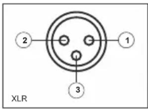
21) CH2 Subnet 2 RDNet port, through either an RJ 45 connector (CAT5 cable) or a 3-pole XLR socket (see point 20).
22) CH3 Subnet 3 RDNet port, through either an RJ 45 connector (CAT5 cable) or a 3-pole XLR socket (see point 20).
23) CH4 Subnet 4 RDNet port, through either an RJ 45 connector (CAT5 cable) or a 3-pole XLR socket (see point 20).
24) CH5 Subnet 5 RDNet port, through either an RJ 45 connector (CAT5 cable) or a 3-pole XLR socket (see point 20).
25) CH6 Subnet 6 RDNet port, through either an RJ 45 connector (CAT5 cable) or a 3-pole XLR socket (see point 20).
26) CH7 Subnet 7 RDNet port, through either an RJ 45 connector (CAT5 cable) or a 3-pole XLR socket (see point 20).
27) CH8 Subnet 8 RDNet port, through either an RJ 45 connector (CAT5 cable) or a 3-pole XLR socket (see point 20).
SUBNET CONNECTION
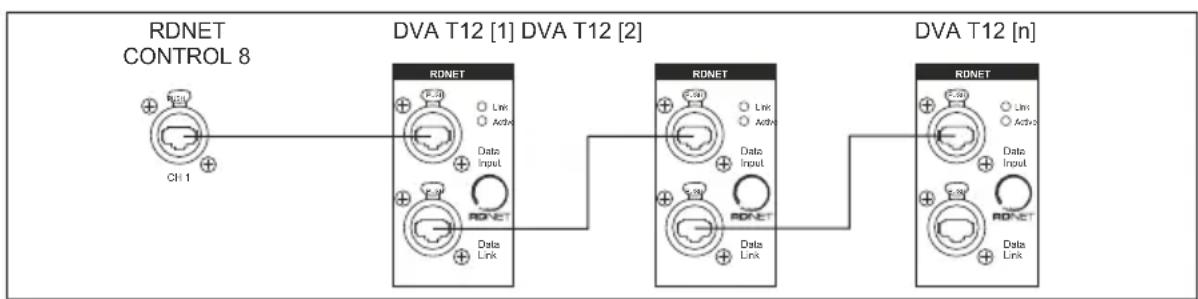
Each of the 8 available RDNet ports of the RDNet Control 8 unit can be connected to max. 32 compatible audio devices (linked in 'daisy-chain').
Example: the RDNet Control 8 port 1 is connected to the DATA IN input of a DVA T12 loudspeaker, of which DATA LINK parallel output is linked to the input of the following DVA T12 loudspeaker.
flowchart
graph LR
    A["RDNET CONTROL 8"] --> B["DVA T12 [1"]]
    B --> C["DVA T12 [2"]]
    C --> D["DVA T12 [n"]]
    A -->|CH 1| E["RDNET"]
    B -->|Link| F["RDNET"]
    C -->|Link| G["RDNET"]
    D -->|Link| H["RDNET"]
    E --> I["Data Input"]
    F --> J["Data Input"]
    G --> K["Data Input"]
    H --> L["Data Input"]
In the example above, [n] is a number from 3 to 32 (max. quantity of audio devices that can be connected to a subnet).
The total CAT 5 cable length of a subnet cannot exceed 900 metres (c. 2950 feet).
NOTES ABOUT THE RDNET SOFTWARE
The RDNet software is protected by international copyright laws and is to be used to configure the dB Technologies RDNet system only.
It is not allowed to modify or change or try to decompile this software.
n no event shall dB Technologies be liable to end-users for any damage whatsoever, including but not limited to financial damages for loss of business profits or business information due to the software use or inability to use this product. The foregoing provision is effective even if dB Technologies has been advised of the possibility of such damages.
Even if the software has any material, verifiable and reproducible program errors, dB Technologies shall have no obligation to modify such errors.
DVA Network
Rdnet Control 8 is equipped with proprietary network interface, called RDNet, for PC interface.
For this purpose, a proprietary communication protocol has been developed for receiving and sending data; this connection permits real-time monitoring of the diffuser parameters, such as output power, amplifier temperature, limiter status, etc...
It is also possible to select various equalizations or create new ones, set the desired volume levels using the specific plug-in.

It is recommended to download DVA Network free software directly from dB Technologies (www.dbtechnologies.com) in the special section «Software & Controller»
SPECIFICATIONS
Network:
- standard EIA RS-485
- up to 8 managed subnet
- max. 32 audio devices connected to each subnet
RDNET connections:
- 8 RJ 45 connectors (EtherCon) for CAT 5 cable
- 8 three-pole XLR plugs (as alternative to RJ 45)
PC connection:
- local: USB (type B)
- remote (alternative to USB): Ethernet (RJ 45)
Power supply:
- operating voltage: 100 ÷ 240 V ac (full range), 50 - 60 Hz (automatic selection)
- consumption: < 15 W
- connector: 'Powercon' type
Mechanical characteristics:
- Dimensions (w, h, d): 482 mm, 44 mm, 182 mm (one 19" rack unit)
- Net weight: 2 kg (4.4 lbs)
- Chassis material: pre-galvanized steel and painted
EMI CLASSIFICATION
According to the standards EN 55103 this equipment is designed and suitable to operate in E3 (or lower E2, E1) Electromagnetic environments.
WARNING
This equipment is compliant with class A of CISPR 32. In a residential environment this equipment may cause radio interference.
FCC CERTIFICATION
This equipment has been tested and found to comply with the limits for a Class A digital device, pursuant to part 15 of the FCC Rules. These limits are designed to provide reasonable protection against harmful interference when the equipment is operated in a commercial environment. This equipment generates, uses, and can radiate radio frequency energy and, if not installed and used in accordance with the instruction manual, may cause harmful interference to radio communications. Operation of this equipment in a residential area is likely to cause harmful interference in which case the user will be required to correct the interference at his own expense.
Any changes or modifications not expressly approved by the party responsible for compliance could void the user's authority to operate the equipment.
PANNELLI - PANELS
Pannello Frontale - Front Panel

flowchart
graph TD
    A["Link 1"] --> B["9"]
    C["Link 2"] --> D["10"]
    E["Link 3"] --> F["11"]
    G["Link 4"] --> H["12"]
    I["Sensor"] --> J["13"]
    K["Radio Receiver"] --> L["14"]
    M["USB"] --> N["15"]
    O["RDNET CONTROL 8"] --> P["16"]
    Q["Power"] --> R["17"]
Pannello Retro - Rear Panel

DIMENSIONI / DIMENSIONS

natural_image
Front view of a network switch device with indicator lights and ports (no readable text or symbols)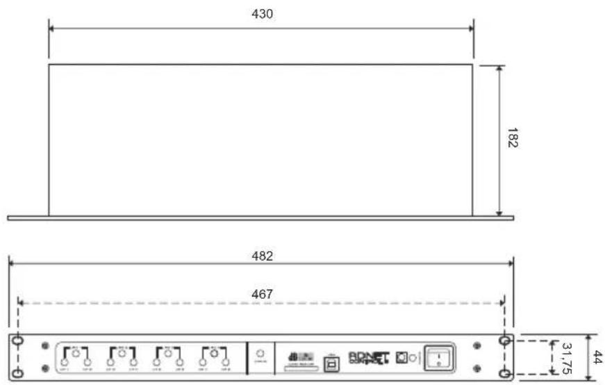

A.E.B. INDUSTRIALE s.r.l.
- DESCRIPTION
- FRONT PANEL (refer to page 9)
- REAR PANEL (refer to page 9)
- DO NOT CONNECT BOTH RJ 45 AND XLR CONNECTORS AT THE SAME RDNET
- PORT!
- RJ 45 CONNECTOR
- XLR SOCKET
- SUBNET CONNECTION
- NOTES ABOUT THE RDNET SOFTWARE
- DVA Network
- SPECIFICATIONS
- Network:
- RDNET connections:
- PC connection:
- Power supply:
- Mechanical characteristics:
- EMI CLASSIFICATION
- WARNING
- FCC CERTIFICATION
- PANNELLI - PANELS
- DIMENSIONI / DIMENSIONS
Brand : DB Technologies
Model : CONTROL 8
Category : Loudspeaker