
BAS 65 - Satellite antenna KATHREIN - Free user manual and instructions
Find the device manual for free BAS 65 KATHREIN in PDF.
| Product type | Flat satellite antenna |
| Brand | Kathrein |
| Model | BAS 65 |
| Reference | 20010032 |
| Dimensions (without bracket) | 500 x 500 x 121 mm |
| Weight (packaged) | 8.2 kg |
| Frequency range | 10.70-12.75 GHz |
| LNB noise figure | Typ. 0.8 dB |
| Gain | >50 dB |
| LNB type | Integrated Twin-LNB, 2 switchable outputs |
| Elevation adjustment (wall/mast mount) | 0° - 57° (wall/mast), 32° - 90° (ground) |
| Azimuth adjustment | ±65° (wall), 360° (mast) |
| Power supply | Via downlead cable (11.5-14 V vertical, 16-19 V horizontal) |
| Maximum consumption | 250 mA |
| Main functions | Reception of analog and digital TV and radio programs, satellite signals |
| Maintenance | No maintenance required; clean with clear water or household detergent |
| Safety | Do not install under power lines; ground according to EN 50083-1; do not open the antenna |
| Spare parts and repairability | Contact customer service (ESC Electronic Service Chiemgau GmbH); do not open yourself |
| General information | Domestic antenna, fixed use, max. height 20 m above ground |
Frequently Asked Questions - BAS 65 KATHREIN
User questions about BAS 65 KATHREIN
0 question about this device. Answer the ones you know or ask your own.
Ask a new question about this device
Download the instructions for your Satellite antenna in PDF format for free! Find your manual BAS 65 - KATHREIN and take your electronic device back in hand. On this page are published all the documents necessary for the use of your device. BAS 65 by KATHREIN.
USER MANUAL BAS 65 KATHREIN

m = 311
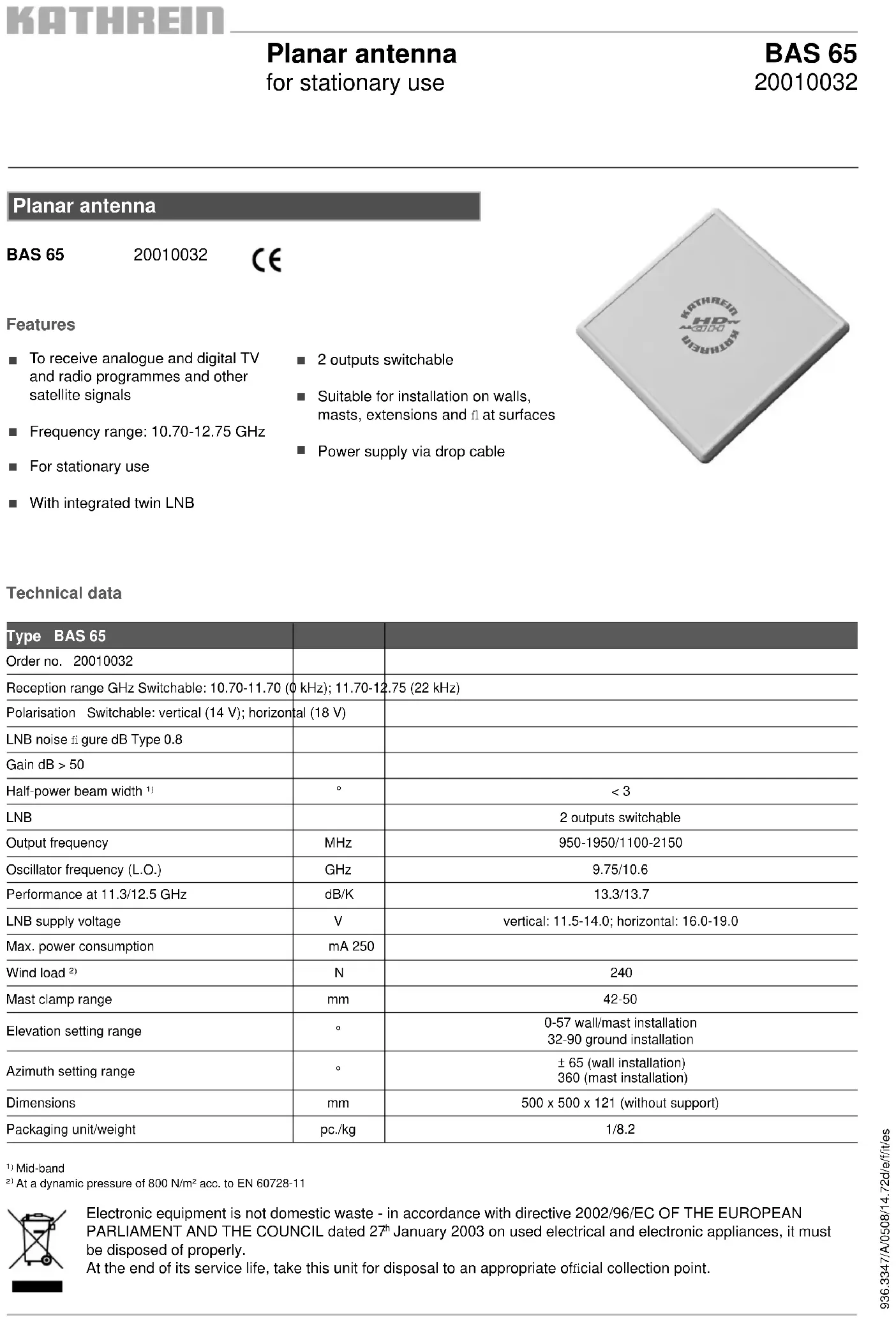
To receive analogue and digital TV and radio programmes and other satellite signals
Frequency range: 10.70-12.75 GHz
For stationary use
With integrated twin LNB
2 outputs switchable
Suitable for installation on walls, masts, extensions and at surfaces
Power supply via drop cable

Technical data
| Type BAS 65 | ||
| Order no. 20010032 | ||
| Reception range GHz Switchable: 10.70-11.70 (0 kHz); 11.70-12.75 (22 kHz) | ||
| Polarisation Switchable: vertical (14 V); horizontal (18 V) | ||
| LNB noise figure dB Type 0.8 | ||
| Gain dB > 50 | ||
| Half-power beam width1) | ° | < 3 |
| LNB | 2 outputs switchable | |
| Output frequency | MHz | 950-1950/1100-2150 |
| Oscillator frequency (L.O.) | GHz | 9.75/10.6 |
| Performance at 11.3/12.5 GHz | dB/K | 13.3/13.7 |
| LNB supply voltage | V | vertical: 11.5-14.0; horizontal: 16.0-19.0 |
| Max. power consumption | mA 250 | |
| Wind load2) | N | 240 |
| Mast clamp range | mm | 42-50 |
| Elevation setting range | ° | 0-57 wall/mast installation32-90 ground installation |
| Azimuth setting range | ° | ± 65 (wall installation)360 (mast installation) |
| Dimensions | mm | 500 x 500 x 121 (without support) |
| Packaging unit/weight | pc./kg | 1/8.2 |
Mid-band
2: At a dynamic pressure of 800N / m^2 acc. to EN 60728-11

Electronic equipment is not domestic waste - in accordance with directive 2002/96/EC OF THE EUROPEAN PARLIAMENT AND THE COUNCIL dated 27^th January 2003 on used electrical and electronic appliances, it must be disposed of properly.
At the end of its service life, take this unit for disposal to an appropriate official collection point.
1. PROPER USE (USE FOR THE INTENDED PURPOSE)
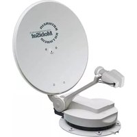
The BAS 65 planar antenna is to be used exclusively for the reception of satellite signals in the analogue and digital frequency ranges and is only intended for private use as a household antenna*. The BAS 65 planar antenna is only designed for stationary use and may be installed at a maximum height of 20 meters above ground level.
Any use other than that specified above will void the warranty or guarantee.
The antenna fulfils the requirements of EN 50083-1 (this standard is authoritative for general use of the BAS 65 planar antenna).
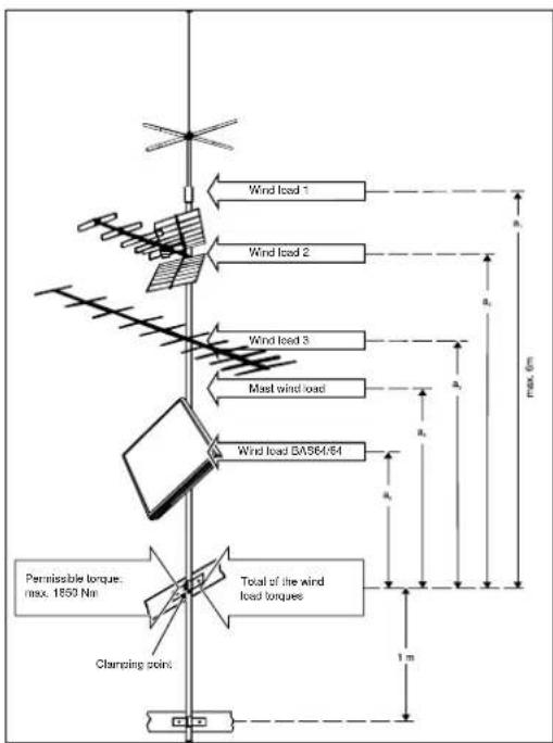
- A household antenna refers to an antenna with a free mast length of maximum 6 m and a clamping torque of up to 1650 Nm (see also DIN 4131).
The following circumstances result in the loss of all warranty and liability claims towards the manufacturer:
- Improper installation
- Use of non-specified mounting materials, which cannot guarantee the mechanical reliability of the antenna system
- Non-permissible use, e.g. use of the planar antenna for storage
- Structural changes or interference with the components and mounting accessories in the set, which could endanger both the mechanical and functional reliability
- Improper or forcible opening of the components
- Use of cleaners containing solvents, such as acetone, nitro-cellulose combination thiners, petrol etc.
- Failure to observe installation and safety instructions in this manual
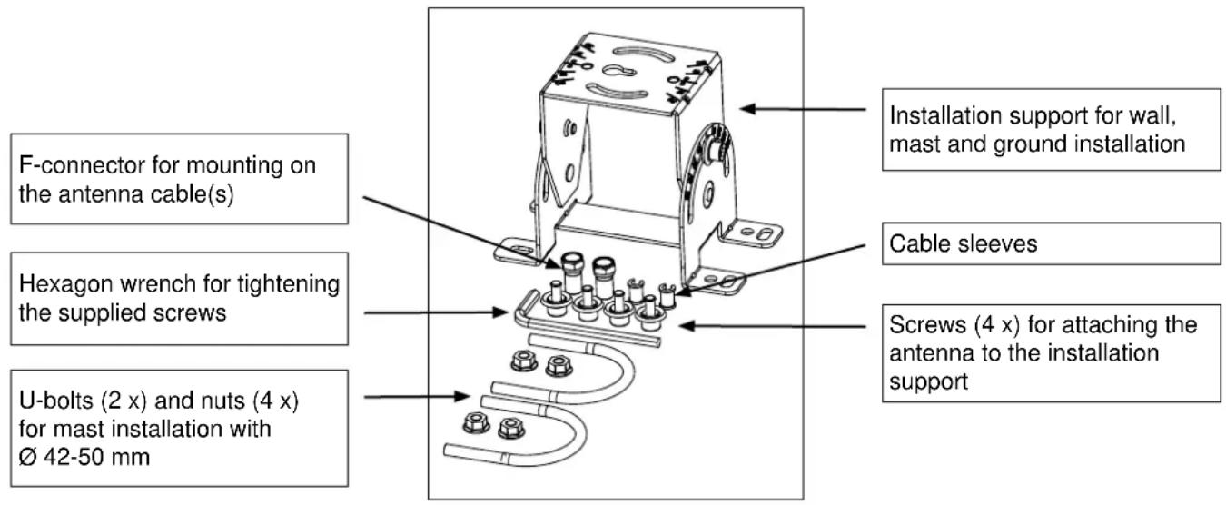
2. Scope of delivery (Fig. A)
The BAS 65 planar antenna is preassembled in the factory before delivery. The enclosed components shown in the picture below are exceptions to this.
3. Dimensions (in mm) and installation options
3.1 Wall installation (see 5.3)
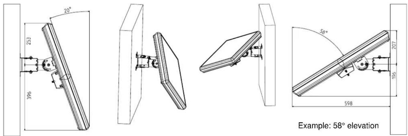
3.2 Mast installation (see 5.4)

3.3 Ground installation (see 5.5)

4. Important Information
Before you mount, connect or use the planar antenna, make sure that you observe the information in these instructions for use.

Warning:
If you do not observe this information:

- The antenna or installation site could be damaged by errors in installation or connection, or by changes to the components or the use of other components
- Improper conduct can lead to health and safety dangers for you and other persons
- The manufacturer is not liable for any functioning errors or damage resulting from this
When performing work on antenna systems, please act responsibly towards yourself and others.
Tip: Keep these instructions safe for future reference and give them to the next owner if the antenna is sold.
Tip: Azimuth setting = Turn the antenna horizontally
Elevation setting = Tilt or lean the antenna vertically
Polarisation setting = Tilt or lean the antenna horizontally
5. Installation
5.1 Selection of the installation site
Danger!

- Never mount an antenna below overhead power lines. This may cause the required minimum safety clearances to be violated. Maintain a minimum clearance of 1m from all other electrical devices on every side! There is a danger to life if you or any of the antenna parts come into contact with electrical devices!
- Never mount antennas on buildings with highly flammable roof coverings (straw, reeds or similar materials). There is a danger of fire in the case of atmospheric overvoltage (static charge) and lightning discharge.
A proper installation site is essential for the safe installation of your planar antenna and for its optimal functioning. For this, please note:
a) Clear line of sight to the satellite
For good reception, a clear line of sight in the southern direction (± 20^) must be ensured.
For some satellites (e.g. TÜRKSAT 1C, HISPASAT) the angular separation from south (azimuth) is greater than ± 20^ .
The elevation angle from horizontal (elevation) must come to approx. 30^ .
A clear line of sight to the satellite means that there are no obstacles (e.g. trees, buildings, balconies, roof overhangs, etc.) between the planar antenna and the satellite.
Such obstacles can impact reception and may even lead to complete failure.
b) Safe installation
In contrast to rod antennas, it is not the installation height above the ground but rather the clear line of site to the satellite that is important for your planar antenna, as for satellite antennas in general. For this reason, an appropriate installation site might also be found in a garden, on a terrace or balcony, or on a facade or garage. If possible, therefore, you should avoid mounting the planar antenna on a rooftop. This will result in less work for you and will reduce the dangers associated with installation work on the roof.
5.2 Safety information for installation of the support and the antenna
Warning!
- Installation of the planar antenna can lead to health and safety risks!
For this, please note the following:
- The installation steps described here require good technical abilities and knowledge about the behaviour of the material under the impact of wind and weather conditions. It is therefore essential to have this work performed by a specialist if you do not possess the required skills.

- Wall mounting: before drilling the holes, make sure there are no electrical cables in the wall. Risk of death due to electric shock.
- Use a properly rigged safety belt when climbing onto roofing or other places where there is a danger of falling.
- Make sure that the roof is able to bear your weight. Never cross fragile or unstable surfaces! Wear secure, anti-slip shoes!
- Ladders and climbing aids must be in sound condition.
- If there are any risks to passersby from falling parts, you must block off the work area and/or danger area!
- Watch out for open wires! There is a serious danger to life if these are touched!
- Never work on antenna systems during a thunderstorm - serious danger to life!
5.3 Wall installation
5.3.1 Attaching the installation support to the wall
Before attaching the installation support for the antenna, ensure that the installation site you have selected offers sufficient purchase for mounting the antenna. Then mount the enclosed installation support for the antenna on the wall using the appropriate mounting supplies, e.g. 4 × screws 6 ~mm and dowels (not included in the delivery).
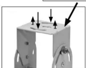
Ensure that the "THIS SIDE UP" inscription on the installation support is pointing upwards.
After installing the support, continue with the point "Attachment of the antenna to the installation support for mast and wall installation" in these instructions for use.

"THIS SIDE UP" inscription
5.3.2 Setting the elevation for wall installation
The antenna elevation should be set before installation (chart and screws are more highly visible/accessible). Perform setting of the antenna as follows, using the printed elevation table found at the end of these instructions for use.
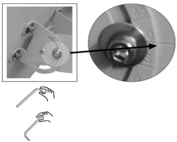
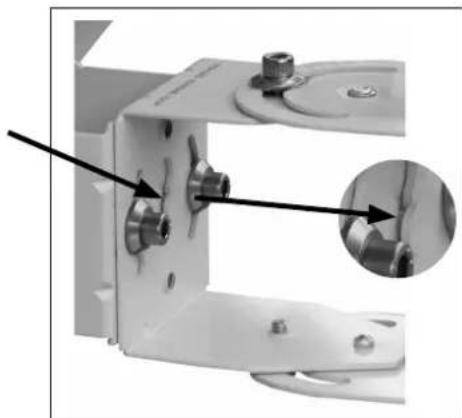
- Loosen the two screws on the support using the enclosed hexagon wrench (see picture on right).
- Now set the elevation value appropriate for you (see table at the end of these instructions for use) on the antenna. For this, ensure that the desired value on the chart is at the same level as the notch on the support (see detail on right).
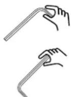
- Hand-tighten the two screws again by gripping the wrench at the short end.
- Grip the wrench at the long end and tighten the screws by approx. 1/4 to 1/2 turns.
The screw-tightening torque now corresponds to approx. 6 to 7Nm
5.3.3 Attaching the antenna to the installation support taking into account the required polarisation value for wall installation
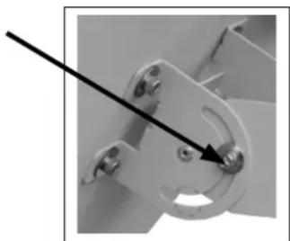
- Take the antenna with the preset elevation and insert the central bolt on the antenna support in the opening (keyhole) provided for this in the centre of the installation support. Press the antenna downwards until the central bolt is in the narrowed area and the antenna can no longer fall out.
- When attaching the antenna, observe the polarisation setting to be determined under point 5.6 and turn the antenna support by the appropriate number of degrees. For this, note the direction (looking toward the satellite, + to the right and - and to the left). The chart for the polarisation setting is on the front of the flat surface of the installation support where the antenna and the support are screwed together (see the picture below on the right).
- Now attach the antenna to the support using the four supplied screws (see picture above on the right). Insert two screws through the curved long holes and into the thread of the counterpartie and hand-tighten them.
- With the remaining two screws, proceed in the same way from the opposite side.
- Use the enclosed hexagon socket wrench to tighten the screws. First, tighten the screws slightly by gripping the wrench at the short end.
- Then grip the wrench at the long end and tighten the screws by approx. 1/4 to 1/2 turns.
The screw-tightening torque now corresponds to approx. 6 to 7Nm
Continue with point 6 of the instructions for use.


Polarisation setting
5.4 Mast installation
5.4.1 Attaching the installation support to a mast or a wall support
Recommended accessories:
When selecting the antenna support, observe the requirements according to point 5.4.1 (see below). For example, these requirements are sufficient for the Kathrein wall supports ZAS 61, ZAS 62 and ZAS 63, the Kathrein masts ZAS 05 and ZAS 06 and the rafter supports ZAS 40 and ZAS 41.
Demands made on the antenna supports (masts)
- Only use masts or supports that are specially suited for use as antenna supports.
Other types of mounting often do not possess the required level of sturdiness under wind and weather conditions. - Select a tube diameter between 42 and 50~mm and a wall thickness of at least 2mm .
- If a mast is installed on a roof, ensure that the mast is clamped for at least a sixth of the free length. Ensure that the permissible clamping torque of the mast is not exceeded.
- For this reason, install the antenna as low as possible on the mast. This is particularly important for masts on which other antennas have already been mounted. If necessary you must have the clamping torque checked mathematically or calculated by a specialist as according to EN 0855-1. The image on the right shows an installation example as described in EN 0855-1.
- When installing the antenna mast, ensure that it is standing upright. Otherwise, there may be problems with the alignment of the antenna and the satellites.

Tip: When attaching the installation support to the mast, observe the azimuth setting required by the antenna (see azimuth/elevation table at the end of these instructions for use) so that the antenna later only needs to be minimally horizontally realigned.
Then attach the installation support (as on the right in the picture) to the mast using the two supplied u-bolts.
Ensure that the "THIS SIDE UP" inscription on the installation support is pointing upwards.
5.4.2 Setting the elevation for wall installation
The antenna elevation should be set before installation (chart and screws are more highly visible/accessible). Perform setting of the antenna as follows, using the printed elevation table found at the end of these instructions for use.
- Loosen the two screws on the support using the enclosed hexagon wrench (see picture on right).
- Now set the elevation value appropriate for you (see table at the end of these instructions for use) on the antenna. For this, ensure that the desired value on the chart is at the same level as the notch on the support (see detail on right).
- Hand-tighten the two screws again by gripping the wrench at the short end.
- Grip the wrench at the long end and tighten the screws by approx. 1/4 to 1/2 turns.
The screw-tightening torque now corresponds to approx. 6 to 7Nm

5.4.3 Attaching the antenna to the installation support taking into account the required polarisation value for mast installation
- Take the antenna with the preset elevation and insert the central bolt on the antenna support in the opening (keyhole) provided for this in the centre of the installation support. Press the antenna downwards until the central bolt is in the narrowed area and the antenna can no longer fall out (see picture on right).

Continued on the next page
- When attaching the antenna, observe the polarisation setting to be determined under point 5.6 and turn the antenna support by the appropriate number of degrees. For this, note the direction (looking toward the satellite, "+" to the right and "-" and to the left). The chart for the polarisation setting is on the front of the flat surface of the installation support where the antenna and the support are screwed together (see the picture below on the right).
- Now attach the antenna to the support using the four supplied screws (see picture above on the right). Insert two screws through the curved long holes and into the thread of the counterpartie and hand-tighten them.
- With the remaining two screws, proceed in the same way from the opposite side.
- Use the enclosed hexagon socket wrench to tighten the screws. First, tighten the screws slightly by gripping the wrench at the short end.
- Then grip the wrench at the long end and tighten the screws by approx. 1/4 to 1/2 turns. The screw-tightening torque now corresponds to approx. 6 to 7 Nm.
Continue with point 6 of the instructions for use.
5.5 Ground installation
5.5.1 Attaching the installation support on the ground

Tip: When attaching the installation support to the ground, ensure that there is sufficient distance between the rear side of the antenna and any walls in order to avoid hitting walls when using the required elevation angle in the antenna (on the rear side, the antenna may extend beyond the installation support depending on the required elevation angle, see 3.3). In addition, when performing ground installation, observe the azimuth setting required by the antenna (see azimuth/elevation table on pages 66-69 and the picture below) so that the antenna later only needs to be minimally horizontally realigned.
Before attaching the installation support for the antenna, ensure that the installation site you have selected offers sufficient purchase for mounting the antenna.
Ensure that the "THIS SIDE UP" inscription on the installation support is pointing towards the side facing away from the satellite.
Then mount the enclosed installation support for the antenna on the ground using the appropriate mounting supplies, e.g. 4 × screws 6 ~mm and dowels (not included in the delivery).

5.5.2 Setting the polarisation for ground installation
The polarisation setting of the antenna should be performed before installation (the weight of the antenna must not then be supported simultaneously). Perform the setting as follows for the polarisation setting degree you have determined under 5.6.
- Loosen the two screws on the support using the enclosed hexagon wrench (see picture on right).
- Now set the polarisation value appropriate for you (see 5.4) on the installation support. For this, ensure that the desired value on the chart is located at the same level as the notch on the support (looking toward the satellite, +^ to the right and -^ and to the left; in the example at right, -15^ is set).
- Hand-tighten the two screws again by gripping the wrench at the short end.
- Grip the wrench at the long end and tighten the screws by approx. 1/4 to 1/2 turns.
The screw-tightening torque now corresponds to approx. 6 to 7Nm

5.5.3 Setting the elevation for ground installation
For ground installation, the elevation setting cannot be performed using the chart on the antenna support, as this is designed for mast and wall installation. For ground installation, the installation support is mounted tipped at a 90^ angle. The required elevation setting for ground installation is calculated as follows:
Ground elevation = 90^ - elevation table value (see page 66-69).
Example for Rosenheim: Elevation table value 35^ ground elevation = 90^ - 35^ = 55^ of the value to be set
- Loosen the two screws on the support using the enclosed hexagon wrench (see picture on right).
- Set the calculated ground elevation value for the antenna support.
- Hand-tighten the two screws again by gripping the wrench at the short end.
- Then grip the wrench at the long end and tighten the screws by approx. 1/4 to 1/2 turns.
The screw-tightening torque now corresponds to approx. 6 to 7Nm
5.5.4 Attaching the antenna to the installation support for ground installation
- Take the antenna and insert the central bolt on the antenna support in the opening (keyhole) provided for this in the centre of the installation support. Pull the antenna forwards in the direction of the satellite until the central bolt is in the narrowed area and the antenna can no longer tip over.
- Now attach the antenna to the support using the four supplied screws (see picture below). Insert two screws through the curved long holes and into the thread of the counterpartie and hand-tighten them. Ensure that the angle is set to 0^
- With the remaining two screws, proceed in the same way from the opposite side.
- Use the enclosed hexagon socket wrench to tighten the screws. First, tighten the screws slightly by gripping the wrench at the short end.
- Then grip the wrench at the long end and tighten the screws by approx. 1/4 to 1/2 turns. The screw-tightening torque now corresponds to approx. 6 to 7 Nm.
Continue with point 6 of the instructions for use.

Azimuth setting level
5.6 Determining the necessary polarisation setting
Satellite signals are sent out with a certain sense of direction, i.e. they are "polarised".
The BAS 65 planar antenna is suited for the reception of linear polarised (horizontal and vertical) signals. To achieve optimal reception in the antenna, it must be aligned in accordance with the geographic location, and its polarisation must if necessary be aligned when attaching the antenna to the installation support. To determine whether your location requires another setting deviating from 0^ , please refer to point 13 on page 70 of these instructions for use. If this is the case, observe the polarisation value when attaching the antenna to the installation support.
6. Connection for the cable(s)
- Prepare the cable, e.g. the LCD 99 from Kathrein (casing diameter: 6.8mm ) according to the figure on the right and twist the enclosed F-connector If you use a cable with a different casing diameter, you must also use an appropriate F-connector for this.
- Loosen the two attachment screws of the LNB covering on the rear side of the antenna and then take off the covering.
- Screw the cables with the connecting nuts of the two F-connectors to the two LNB outputs.
- Guide the two cables (without kinking them) on the sides of the LNB in the output direction
- Guide the two cables towards the exterior through the opening provided for this in the LNB covering Press the two cables into the cable support provided for this. If your cables are too small for the openings provided, use the cable sleeves included with the delivered accessories in order to optimally fill out the openings and to offer the cables a foothold (cable sleeves are clipped to cables and then pressed together into the support).
- Screw the LNB covering on again.


7. Connecting and setting the satellite receiver
- Establish the connection between the planar antenna and the satellite receiver. For this, use the "IF input" sat input on the satellite receiver.
- Connect your TV to the satellite receiver via an audio/video cable. Select the "AV" programme location on your TV.
- If you use the modulator output of the receiver, tune your TV to the channel to which the output channel of the satellite receiver is set.
Save this channel on a free TV programme storage space
- In order to align the antenna with the desired satellites, set an appropriate programme location on the satellite receiver (see also programme table for the receiver).
Please refer to the satellite receiver's operating instructions for detailed usage information.
8. Aligning the antenna
For the following steps you need either a satellite test receiver or a helper who monitors the results of the alignment work on your TV screen.
If you use a satellite test receiver from the Kathrein MSK series, this should be connected to the LNB instead of the antenna cable.
With the test receiver, you align the antenna according to the maximum level. When performing alignment via the TV screen, aim for the best image quality.


8.1 Aligning the antenna for wall and mast installation
8.1.1 Elevation setting
- Loosen the two screws on the support using the enclosed hexagon wrench (see picture on right) and support the antenna manually on the lower side.
- Tip or lean the antenna to the front or back in gradual steps until you obtain an optimal signal.
- Hand-tighten the two screws again by gripping the wrench at the short end.
- Then grip the wrench at the long end and tighten the screws by approx. 1/4 to 1/2 turns. The screw-tightening torque now corresponds to approx. 6 to 7Nm
8.1.2 Azimuth setting
- Loosen the two screws on the support using the enclosed hexagon wrench (see picture on right).
- Turn the antenna to the left or right slowly and at brief intervals until you obtain an optimal signal.
- Hand-tighten the four screws again by gripping the wrench at the short end.
- Grip the wrench at the long end and tighten the screws by approx. 1/4 to 1/2 turns.
The screw-tightening torque now corresponds to approx. 6 to 7Nm

8.2 Aligning the antenna for ground installation
8.2.1 Elevation setting
- Loosen the two screws on the support using the enclosed hexagon wrench (see picture on right) and support the antenna manually.
- Tip or lean the antenna to the front or back in gradual steps until you obtain an optimal signal.
- Hand-tighten the two screws again by gripping the wrench at the short end.
- Then grip the wrench at the long end and tighten the screws by approx. 1/4 to 1/2 turns.
The screw-tightening torque now corresponds to approx. 6 to 7Nm

8.2.2 Azimuth setting
- Loosen the four screws on the support using the enclosed hexagon wrench (see picture on right).
- Turn the antenna to the left or right slowly and at brief intervals until you obtain an optimal signal.
- Hand-tighten the four screws again by gripping the wrench at the short end.
- Grip the wrench at the long end and tighten the screws by approx. 1/4 to 1/2 turns.
The screw-tightening torque now corresponds to approx. 6 to 7Nm

For a polarisation setting deviating from 0^ , the elevation angle is adjusted marginally by optimising the azimuth setting. This can be balanced by repeatedly readjusting the elevation angle, as described under 8.2.1.
When you have aligned and attached the antenna, check again to ensure that all screw connections are secure.
Attach the antenna cable on the antenna support (e.g. with cable retainers) so that it is not chafed or damaged.
9. Antenna grounding/lightning protection
The antenna must be grounded according to the German VDE regulation EN 50083-1.
The only exceptions to this are exterior antennas
- that are fitted more than 2m below the roof edge
- and are also fitted less than 1.5m from the building.
Danger may be caused not only by thunderstorms (lightning), but also by static charge and short circuits in the connected units.
For this reason, the antenna support and the external conductors of the antenna cable must be connected with the lightning protection of the building via the shortest vertical path and using an appropriate grounding conductor (if there is no lightning protection system, then they must be connected with the building grounding).
- An appropriate grounding conductor is a single solid wire with a minimum cross section of 16mm^2 for copper, 25mm^2 for aluminium or 50mm^2 for steel or
metallic domestic installations, e.g. continuous metallic water or heating system pipes, provided that they at least meet the requirements for grounding conductors in terms of cross-section and permanence of the electrical connection.
- Inappropriate grounding conductors are the exterior conductors of the antenna cable, the grounding conductor or neutral conductor of the power system.
Antenna cables and grounding conductors must not be routed through rooms used for storing easily flammable substances (hay or straw, for example) or in which an explosive atmosphere can develop (e.g. gases, vapours).
If the planar antenna is used in integrated antenna systems (e.g. distribution systems), the grounding measures must also be designed in such a way that grounding protection is still maintained if individual units are removed or replaced.
Warning:

- Grounding and lightning protection work may only be performed by specially trained electricians due to the dangers associated with deficient work results!
form grounding or lightning protection work if you are not a specialist with the appropriate skills!
The information printed here is not an invitation to non-specialists to perform grounding and lightning protection work on their own, but is rather intended to provide the specialists commissioned by you with additional information!
10. Maintenance and cleaning of the antenna
The BAS 65 planar antenna does not require maintenance.
Only clean the antenna with water and, if necessary, with added household cleaning agents.
Never use steam jet or high pressure cleaners or solvent-containing cleaners such as acetone, nitro-paint thinners, benzine etc. These could damage the antenna.
11. Malfunctioning
| Malfunction Possible cause | ||||
| No picture - Obstacle between antenna and satellite | ||||
| - TV or receiver is defective or without voltage | ||||
| - Antenna cable connector is loose | ||||
| Poor image quality - Obstacle between antenna and satellite | ||||
| (partial shadowing of the satellite signal) | ||||
| - Foliage, snow, ice, etc. covering the antenna | ||||
| - Antenna cable connector is loose | ||||
| Note:If you cannot identify and remedy a malfunction, contact your responsible specialist or our service centre. Never open the antenna yourself! | ||||
| The address of our service centre is: | ESC Electronic Service Chiemgau GmbH | |||
| Bahnhofstrasse 108 | ||||
| 83224 Grassau, Germany | ||||
| Tel.: +49 8641 9545-0 | ||||
| Fax: +49 8641 9545-35 | ||||
| e-mail: service@esc-kathrein.de | ||||
| Website. www.esc-kathrein.de | ||||
12. Azimuth/elevation tables (see pages 66-69)
For an initial approximation, the table values for EUTELSAT II F1 13^ can be used for the satellites EUTELSAT II F2 10^ and for EUTELSAT II F3 16^ .
| Tip: | Azimuth setting = Turn the antenna horizontally Elevation setting = Tip or lean the antenna vertically |
13. Polarisation table (see page 70)
| Tip: Polarisation setting = Tip or lean the antenna horizontally |
Antenna plane
BAS 65
20010032

\section*{Caracteristiques}

m = 311 ;
936.3347/A/0508/71.72d/e/f/it/es
|  | ||||||||||||||||||||||||||||||||||
|  | ||||||||||||||||||||||||||||||||||
|  | ||||||||||||||||||||||||||||||||||
|  | ||||||||||||||||||||||||||||||||||
|  | ||||||||||||||||||||||||||||||||||
|  |
936.3347/A/0508/72.72d/e/f/it/es


- Technical data
- PROPER USE (USE FOR THE INTENDED PURPOSE)
- The following circumstances result in the loss of all warranty and liability claims towards the manufacturer:
- Scope of delivery (Fig. A)
- Dimensions (in mm) and installation options
- Wall installation (see 5.3)
- Mast installation (see 5.4)
- Ground installation (see 5.5)
- Important Information
- Warning:
- Installation
- Selection of the installation site
- Danger!
- a) Clear line of sight to the satellite
- b) Safe installation
- Safety information for installation of the support and the antenna
- Warning!
- Wall installation
- Attaching the installation support to the wall
- Setting the elevation for wall installation
- Attaching the antenna to the installation support taking into account the required polarisation value for wall installation
- Mast installation
- Attaching the installation support to a mast or a wall support
- Recommended accessories:
- Demands made on the antenna supports (masts)
- Setting the elevation for wall installation
- Attaching the antenna to the installation support taking into account the required polarisation value for mast installation
- Continued on the next page
- Ground installation
- Attaching the installation support on the ground
- Setting the polarisation for ground installation
- Setting the elevation for ground installation
- Attaching the antenna to the installation support for ground installation
- Determining the necessary polarisation setting
- Connection for the cable(s)
- Connecting and setting the satellite receiver
- Aligning the antenna
- Aligning the antenna for wall and mast installation
- Elevation setting
- Azimuth setting
- Aligning the antenna for ground installation
- Elevation setting
- Azimuth setting
- Antenna grounding/lightning protection
- Maintenance and cleaning of the antenna
- Malfunctioning
- Azimuth/elevation tables (see pages 66-69)
- Polarisation table (see page 70)
- Antenna plane
- \section*{Caracteristiques}
Brand : KATHREIN
Model : BAS 65
Category : Satellite antenna