
CAS 124 - Satellite antenna KATHREIN - Free user manual and instructions
Find the device manual for free CAS 124 KATHREIN in PDF.
| Product Type | Parabolic satellite antenna |
| Brand | Kathrein |
| Model | CAS 124 |
| Reference | 216236 |
| Reflector Diameter | 1.2 m |
| Reception Range | 10.70 – 12.75 GHz |
| Antenna Gain (11.70-12.50 GHz) | 42.15 dBi |
| Beamwidth (mid-band) | 1.43° |
| Cross Polarization Decoupling | > 30 dB |
| Reflector Material | Powder-coated aluminum, matte white (RAL 9002) |
| Mount Support | Aluminum and stainless steel |
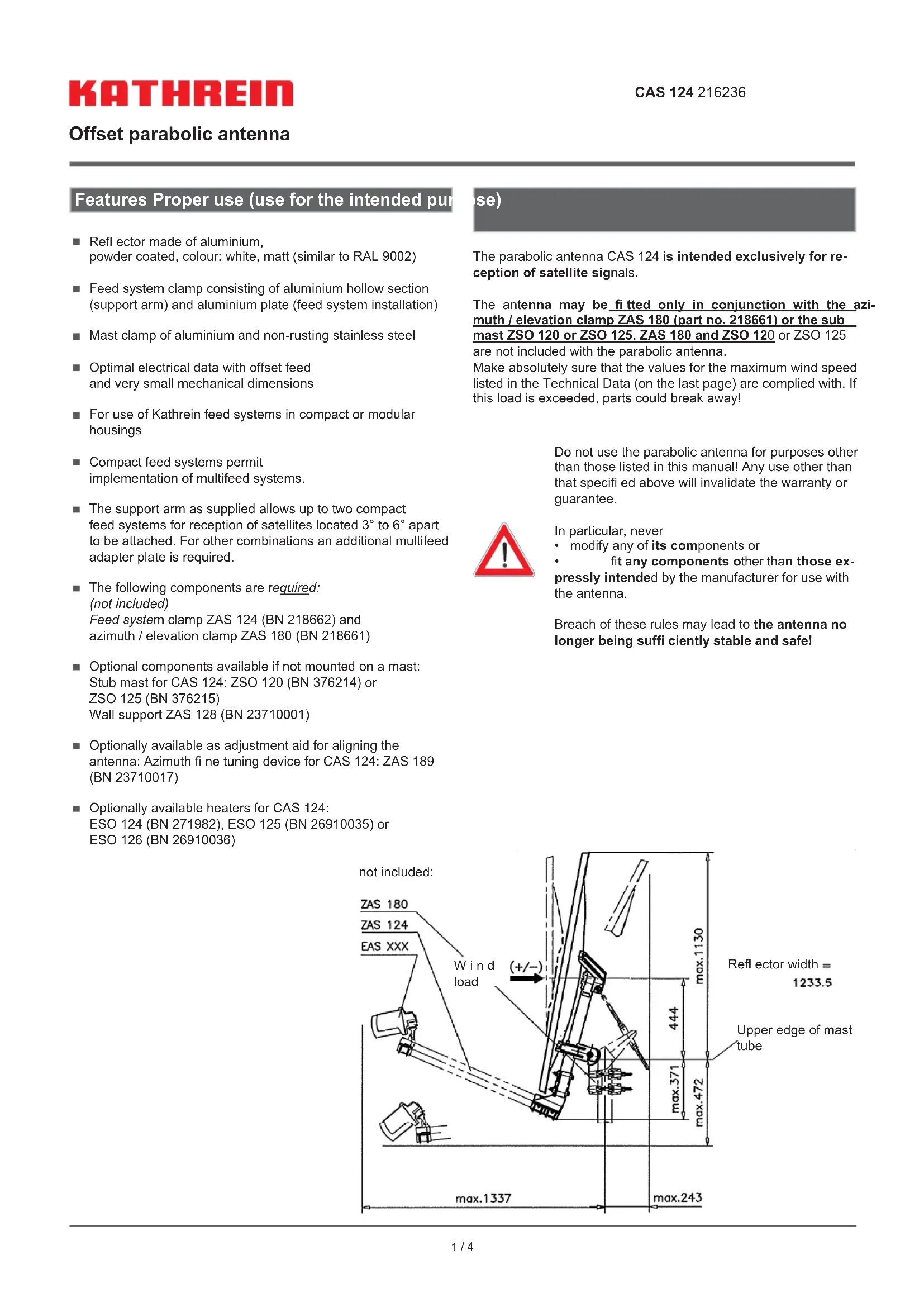
| Dimensions (W x H x D) | 1234 x 1501 x 1337 mm (max offset from mast center) |
| Net Weight | 18.4 kg |
| Gross Weight | 30.7 kg |
| Exposed Wind Area | 1.292 m² |
| Maximum Permissible Wind Speed | 200 km/h (load 3366 N) |
| Clamp Tightening Range | 75 – 114 mm |
| Elevation Adjustment Range | 5 – 50° |
| Azimuth Adjustment Range | 360° |
| Main Functions | Reception of satellite signals, Multifeed compatible (up to 2 LNB with original support), precise alignment |
| Safety | Strict installation instructions: avoid power lines, use safety equipment, grounding according to DIN EN 60728-11 |
| Spare Parts (not supplied) | Azimuth/elevation mount ZAS 180, feed support system ZAS 124, feet ZSO 120/125, wall mount ZAS 128, fine adjustment ZAS 189, heaters ESO 124/125/126 |
| Maintenance | Clean with a soft, dry cloth; regularly check fastening and general condition |
| Warranty | Void if used improperly or unauthorized modifications are made |
Frequently Asked Questions - CAS 124 KATHREIN
User questions about CAS 124 KATHREIN
0 question about this device. Answer the ones you know or ask your own.
Ask a new question about this device
Download the instructions for your Satellite antenna in PDF format for free! Find your manual CAS 124 - KATHREIN and take your electronic device back in hand. On this page are published all the documents necessary for the use of your device. CAS 124 by KATHREIN.
USER MANUAL CAS 124 KATHREIN
As of 1 April 2019, KATHREIN SE's (formerly KATHREIN-WERKE KG) "Terrestrial & Satellite Reception" business unit will be transferred to KATHREIN Digital Systems GmbH (limited liability company).
From 1 April 2019, the new company data are:
KATHREIN Digital Systems GmbH
Anton-Kathrein-Str. 1-3
83022 Rosenheim, Germany
Tax ID No.: 156/117/31083
natural_image
Technical line drawing of a mechanical component with no visible text or symbols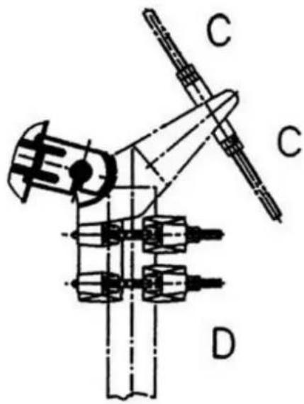
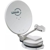
■ Reflector made of aluminium, powder coated, colour: white, matt (similar to RAL 9002)
■ Feed system clamp consisting of aluminium hollow section (support arm) and aluminium plate (feed system installation)
■ Mast clamp of aluminium and non-rusting stainless steel
■ Optimal electrical data with offset feed and very small mechanical dimensions
■ For use of Kathrein feed systems in compact or modular housings
■ Compact feed systems permit implementation of multifeed systems.
■ The support arm as supplied allows up to two compact feed systems for reception of satellites located 3^ to 6^ apart to be attached. For other combinations an additional multifeed adapter plate is required.
■ The following components are required: (not included) Feed system clamp ZAS 124 (BN 218662) and azimuth / elevation clamp ZAS 180 (BN 218661)
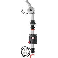
■ Optional components available if not mounted on a mast: Stub mast for CAS 124: ZSO 120 (BN 376214) or ZSO 125 (BN 376215) Wall support ZAS 128 (BN 23710001)
■ Optionally available as adjustment aid for aligning the antenna: Azimuth fi ne tuning device for CAS 124: ZAS 189 (BN 23710017)
■ Optionally available heaters for CAS 124: ESO 124 (BN 271982), ESO 125 (BN 26910035) or ESO 126 (BN 26910036)
se)
The parabolic antenna CAS 124 is intended exclusively for reception of satellite signals.
The antenna may be fitted only in conjunction with the azimuth / elevation clamp ZAS 180 (part no. 218661) or the submast ZSO 120 or ZSO 125. ZAS 180 and ZSO 120 or ZSO 125 are not included with the parabolic antenna.
Make absolutely sure that the values for the maximum wind speed listed in the Technical Data (on the last page) are complied with. If this load is exceeded, parts could break away!
Do not use the parabolic antenna for purposes other than those listed in this manual! Any use other than that specified above will invalidate the warranty or guarantee.

In particular, never
• modify any of its components or
• fit any components other than those expressly intended by the manufacturer for use with the antenna.
Breach of these rules may lead to the antenna no longer being suffi ciently stable and safe!

Basic Safety Precautions
Before you install, connect or use the parabolic antenna, make sure that you comply with the instructions in this manual
- If you disregard these instructions,
- malfunctions may arise, creating risks to your life and health,
• defects in the installation or the connection may cause damage to the antenna or to the attachment point, - the manufacturer will not accept liability for any resulting malfunctions or damage!

- Under no circumstances install antennas in the vicinity of overhead power cables, otherwise the absolutely essential clearance requirements may no longer be satisfied. Maintain a clearance of at least 1 m from all other electrical equipment in all directions!
If you or metal parts of the antenna touch any electrical device there is a serious risk of a fatal electric shock!
- Never work on antenna systems during a thunderstorm or when a thunderstorm is approaching.
There is a risk of a fatal electric shock!
- Never install antennas on buildings with easily flammable roof coverings such as straw, rushes or similar materials! Otherwise there is a risk of fire due to atmospheric over-voltages (static charges) or lightning discharges (e.g. during thunderstorms).
- The installation operations described here assume good craftsmanship capabilities and knowledge of the behaviour of materials under the effects of wind. Therefore if you do not possess the required skills, have this work performed by a specialist.
- The person doing the work must wear strong non-slip footwear, must not be liable to dizziness, must be able to move around safely on the roof and have a secure standing and attachment position. (if necessary, wear a safety harness when on the roof).
- Make sure that the roof is able to bear your weight. Never walk on fragile or unstable surfaces! In case of doubt, contact a qualified specialist dealer or specialist roofing contractor to find an appropriate installation location.
- Do not go on to roofs or other high places without a correctly attached safety harness that is in good condition. Otherwise use a work platform.
- Ladders or other means of climbing must be in faultless condition (dry, clean and non-slip). Never build any irresponsible „scrambling towers“!
- If there is a risk that passers-by may be injured by items falling from above during installation, you must close off the risk area using barriers! Make sure that no-one is underneath the installation location.
Risk of death or injury due to falling from the roof, falling through the roof and falling parts, plus the possibility of damage to the roof.
- The respective national safety regulations and current standards such as DIN EN 60728-11 should be complied with.
- Any other use or failure to comply with these instructions will result in voiding of warranty coverage.

Selecting the installation site
It is essential to select the correct installation site. This determines whether the parabolic antenna can be erected safely and perform to its optimum capabilities.
When selecting the installation site, take account of special features of the structure of the building. If the installation is at the edge of the roof or the building or on a cylindrical structure, DIN 1055, parts 4 and 4131 specifies the increased wind and vibration loadings that should be allowed for. The dynamic properties of the antenna and the structure can interact and cause problems.
Failure to comply can result in excessive susceptibility to vibration.
Antenna grounding / lightning protection

Because of the serious consequences if the work is not done properly, grounding and lightning protection work may be performed only by specially trained electricians.
Never perform grounding and lightning protection work if you are not a specialist with the appropriate skills!
The antenna must be erected to DIN EN 60728-11 and grounded as specified.
Installation
a) Installation sequence
- First attach the azimuth / elevation clamp ZAS 180 to the mast/sub mast/wall bracket (as described in the user instructions for the ZAS 180)
- Slot the antenna on to the pre-erected azimuth / elevation clamp ZAS 180
- Tighten the pre-installed elevation screw "A" on the antenna
- Gently tighten the four centring screws "B"

b) Pre-setting the elevation angle
- Adjust the reflector angle by turning the nuts "C"

natural_image
Technical line drawing of a mechanical component with no visible text or symbols
c) Installation of the feed system clamp ZAS 124
- Install the feed system clamp as described in the user instructions for the ZAS 124
d) Installation of the feed system(s) (LNB)
- Install the LNBs as described in the user instructions for the respective LNBs
The setting of the angle of inclination of the LNB clamp for multifeed applications is described in the user instructions for the ZAS 124.
e) Alignment of the antenna
After fully installing the antenna (including the LNB), use a suitable satellite measurement receiver (e.g. MSK 115, MSK 125 or MSK 200) for fine alignment of the antenna. Kathrein recommends the use of the azimuth fine tuning device ZAS 189 (BN 23710017) for fine alignment of the azimuth angle.
f) Once the antenna has been correctly aligned
Tighten all the securing elements "B", "C" and "D". Table of tightening torques:
| Gew.ø | M10 | M12 | M16 |
| [Nm] | 35 | 60 | 140 |
Technical Specifications
| Type CAS 124 | ||
| Part no. 216236 | ||
| Diameter m 1.2 | ||
| Reception range GHz 10.70-12.75 | ||
| Antenna gain at 10.70-11.70 GHz dBi 41.50 | ||
| Antenna gain at 11.70-12.50 GHz dBi 42.15 | ||
| Antenna gain at 12.50-12.75 GHz dBi 42.50 | ||
| Half power beam width (at the centre of the band) ° 1.43 | ||
| System fi gure of merit (G/T) | See feed systemEAS 483/484/485 | |
| Cross-polarisation decoupling (in main beam direction) | dB | >30 |
| Resulting from wind tunnel trials: | ||
| Wind speed 130 km/h: | ||
| Wind load | N | 1395 |
| dynamic pressure | N/m^2 | 800 |
| Wind speed 164 km/h: | ||
| Wind load | N | 2267 |
| dynamic pressure | N/m^2 | 1300 |
| Wind speed 200 km/h: | ||
| Wind load | N | 3366 |
| dynamic pressure | N/m^2 | 1930 |
| Wind area | m^2 | 1.292 |
| Clamping range of the mast clamp ZAS 180/ZAS 186 | mm | 75-114 |
| Setting range, elevation | ° 5-50 | |
| Setting range, azimuth | ° | 360 |
| Dimensions width | mm | 1234 |
| Max. dimensions, height | mm | 1501 |
| Max. dimensions, protrusion (from centre of mast with a feed system) | mm | 1337 |
| Packaging size (L x W x H) | mm | 1430 x 1430 x 370 |
| Weight approx. net/gross | kg | 18.4/30.7 |
All figures are typical values!

Electronic equipment is not domestic waste: in accordance with directive 2002/96/EC OF THE EUROPEAN PARLIAMENT AND THE COUNCIL dated 27th January 2003 on used electrical and electronic equipment, it must be disposed of properly.
At the end of its service life, take this device for disposal at a designated public collection point.
935.1534/A/ZWT/0710/e - Subject to technical changes!
natural_image
Technical line drawing of a mechanical component with no visible text or symbols


Brand : KATHREIN
Model : CAS 124
Category : Satellite antenna