
HDP 650 GPS - Satellite antenna KATHREIN - Free user manual and instructions
Find the device manual for free HDP 650 GPS KATHREIN in PDF.


| Product Type | Satellite antenna |
| Brand | Kathrein |
| Model | HDP 650 GPS |
| Application | Mobile satellite reception for vehicles |
| Dimensions (DxH) | Approx. 39 cm x 10 cm |
| Weight | Approx. 2 kg |
| Power Supply | 12 V DC |
| Power Consumption | Typ. 15 W |
| Frequency Range | 10.7 – 12.75 GHz |
| Polarization | Linear (H/V) and Circular |
| LNB Type | Universal Quad LNB |
| GPS Receiver | Integrated, 32 channels |
| Tracking | Automatic satellite tracking |
| Number of Satellites | Supports multiple satellites |
| Operating Temperature | -20°C to +60°C |
| Mounting | Roof mount or tripod |
| Protection Class | IP54 |
| Connector | F-type (75 Ω) |
| Included Accessories | Mounting kit, 10 m cable, remote control |
| Maintenance | Clean with soft dry cloth; avoid solvents |
| Safety | Use only with approved 12V supply; professional installation recommended |
| Repairability | Spare parts available via authorized service centers |
Frequently Asked Questions - HDP 650 GPS KATHREIN
User questions about HDP 650 GPS KATHREIN
0 question about this device. Answer the ones you know or ask your own.
Ask a new question about this device
Download the instructions for your Satellite antenna in PDF format for free! Find your manual HDP 650 GPS - KATHREIN and take your electronic device back in hand. On this page are published all the documents necessary for the use of your device. HDP 650 GPS by KATHREIN.
USER MANUAL HDP 650 GPS KATHREIN
natural_image
White KATHREIN transmaxer MobiSat device with attached black PET T800 GPS device, no visible text or symbols on the device itself.Contents
1 General 4
2 Scope of Delivery 5
3 Intended Use 6
4 Safety Instructions and General Guidelines 7
5 Installation and Connection 12
5.1 Installing and Connecting the Turntable 12
5.1.1 Required Tools and Equipment 12
5.1.2 Unpacking and Preparing 12
5.1.3 Selecting the Installation Location 13
5.1.4 Installing the Cable Gland and Mounting Plate 15
5.1.5 Installation of the Turntable 17
5.1.6 Installing the Turntable 19
5.1.7 Laying the Cables and Connecting the Turntable 20
5.1.8 Functional Instructions for Connection to the On-board Power Supply 21
5.1.9 Connection Example for 12 V Battery Connection 22
5.2 Installation and Connection of the CAP Converter 22
5.2.1 Selection of a Suitable Installation Location 22
5.2.2 Preparing the CAP Converter for Installation 24
5.2.3 Important Instructions for Installation 24
5.2.4 Installing the CAP Converter on the Rear Panel of a TV Set 25
5.2.5 Installing the CAP Converter 26
5.2.6 Connecting the CAP converter 27
5.2.7 Connection Example for 12 V Battery Connection 27
5.3 Installation and Connection of the CTS 650-xx GPS 28
6 Reception Range/Footprint 29
7 Dismantling for Servicing 30
7.1 Dismantling the Turntable 30
7.2 Address of the Service Centre 30
8 Polarisation Setting 31
8.1 About Polarisation Setting 31
8.2 Safety Instructions 32
8.3 Setting Operations 32
9 Manually Lowering the Antenna to Park Position 34
9.1 Safety Instructions 34
9.2 Manually Lowering the Turntable 35
10 Technical Data and Dimensions 36
10.1 Technical Data 36
10.2 Dimensions (in mm) 37
11 Safety Instructions and General Guidelines 39
12 CAP 650 GPS Operating Instructions 40
12.1 Installing the CAP Converter 41
12.2 Change of Location 41
12.3 Operating the Turntable Using the External Push-button 41
12.3.1 Starting the Turntable 41
12.3.2 Moving the Turntable to the Park Position. 41
12.3.3 Performing a Reset 41
12.4 Updating Channel List and Software 42
12.4.1 Updating the Channel List 42
12.4.2 Preparing a software update 42
12.4.3 Performing a software update 42
12.5 LED Status Display on the CAP Converter V2 - external Pushbutton 43
12.6 Possible Malfunctions 44
12.6.1 Error Indication on the CAP Converter/External Push-button 44
12.6.2 Other Problems 44
13 Addresses 44
13.1 Service and Support 44
13.2 Factory Repair Centre 44
13.3 Service Partners 44
14 Disposal 44
15 Simplified EU Declaration of Conformity 45
16 Optional accessories 45
17 Connection of the current-carrying cables 46
1 General
Company address
KATHREIN Digital Systems GmbH
natural_image
White KATHREIN transcharger device with MobiSat branding, no visible text or symbols on the device itself
natural_image
Black rectangular electronic device with mounting holes and a label 'SICU-MAN' on the side (no other text or symbols visible)① Turntable with integral controls
② Flat antenna
③ CAP converter V2
The CAP 650 GPS/HDP 650 GPS consists of:
- Turntable ① complete with control electronics, pre-assembled flat antenna ② and twin LNB
- Mounting plate
- Complete cabling set:
1 x master coaxial cable 1) , 3 m, marked in red, for the master connection to the CAP converter V2 2)
1 x slave coaxial cable 1) , 3 m, for connection to a second receiver or TV with an integrated receiver
1 x power supply cable 1) , 3 m
1 x coaxial extension cable, 5 m, F-type female connector to F-type male connector
1 x power supply extension cable, 7 m for connection to the on-board power supply
1 x blade-type fuse and fuse holder
• Roof duct with sealing gasket
- CAP converter V2 ③ with a 12 V connection cable and LED/pushbutton cable 3)
- 4 x wood screw, 4.5 mm x 30 mm
• CAP 650 GPS/HDP 650 GPS operating manual
1) Fixed connection to the turntable
2) A coaxial cable F-socket/F-socket is required to connect the TV set to the CAP converter (cable length depends on the distance between the two devices). This cable is not included. For this, see 12.1 Installing the CAP Converter, p.41.
3) only with CAP 650 GPS
3 Intended Use
The CAP 650 GPS and HDP 650 GPS are designed to receive digital TV and radio channels via satellite. The automatic positioner is intended to be used as a turntable for the Kathrein flat antenna.
The turntable can be used to receive digital TV and radio signals in the frequency range from from 10.70 to 12.75 GHz; the antenna cannot receive terrestrial signals such as DVB-T/DVB-T2.
The CAP 650 GPS is a receiver-independent solution and can be used in conjunction with any satellite-enabled end device. The CAP converter manages the communication and control of the system and converts the signals received from the end device into CAP-compliant signals. This enables the fully automatic alignment of the flat antenna for the reception of digital satellite signals.
The turntable is designed for use on stationary caravans or motor homes.
Any other use than that specified above will invalidate the warranty or guarantee.
The following circumstances result in the loss of all warranty and liability claims towards the manufacturer:
- improper installation
- use of non-specified mounting materials, which cannot guarantee the mechanical reliability of the antenna system
- impermissible use, e.g. use of the flat antenna for storage
- structural changes or interference with the components and mounting accessories in the set, which could endanger both the mechanical and functional reliability
- improper or forcible opening of the components,
- use of cleaners containing solvents, such as acetone, nitro-cellulose thinners, petrol, etc.
- failure to observe installation and safety instructions in this manual
4 Safety Instructions and General Guidelines

Danger to life from electric shock when touching electrical installations!
▶ Maintain a minimum clearance of 1 m from all electrical devices.
▶ Disconnect the turntable and all the units connected to it from the power supply during installation/repairs/dismantling.
▶ Make sure that modifications to the electrical installations in the vehicle are only carried out by a specialist. Do not make any unauthorised changes to the turntable!

Risk of severe injuries during installation/repairs/dismantling on the vehicle roof!
▶ Position the vehicle horizontally.
▶ Wear stable shoes with non-slip soles.
▶ Use a working platform.
▶ Make sure that the person carrying out the installation or repair has a secure position to stand and hold on whilst working.
▶ Make sure that the person carrying out the installation or repair does not suffer from vertigo and can move around safely on the roof of the caravan or motor home.
▶ Make sure that the vehicle roof is sufficiently strong and stable. If in doubt, contact a qualified specialist dealer or the manufacturer of your vehicle.
▶ Make sure that there is nobody below the antenna inside the caravan/motor home during installation/repairs/dismantling.
▶ Make sure that the roof and climbing aid are dry, clean and non-slip.

Risk of severe injuries due to moving parts, especially risk of crushing!
▶ Make sure that no one, and in particular, no children, is in the immediate vicinity of the turntable and cannot touch any moving parts.
▶ Disconnect the turntable and all the units connected to it from the power supply during installation/repairs/dismantling.

Risk of damage when the permissible wind speeds or vehicle speeds are exceeded!
Risk of accidents due to collision of the antenna with objects!
An increase in the normal vehicle height due to the antenna not being lowered can lead to an increased risk of accidents. The driver bears sole responsibility for the condition of the superstructure and external fittings! In stormy weather, the turntable and the vehicle could be damaged.
▶ Follow the instructions in the installation and operating manuals for the units used and for the external fittings and superstructures.
▶ Before commencing a journey or if there is a storm warning (with wind speeds exceeding 90 km/h), lower the antenna into the horizontal position (park position).
▶ Do not exceed the maximum permissible speed for vehicles of 130 km/h.

Risk of malfunction or material damage due to operation outside the permissible temperature range!
▶ Operate the turntable in an ambient temperature range from -20irc C to +45irc C.
▶ When selecting the installation and setup location, ensure that the receiver is sufficiently ventilated.
Proper installation and safety

The system may be installed only by qualified specialist personnel!
To prevent hazards during installation, operation or when driving on public highways, the instructions and information in this manual must be strictly adhered to. Proper installation and connection of the system are prerequisites for conformity with the corresponding standards.
Essential information
A crucial safety factor is proper performance of installation and electrical connection work, and the specified alignment of the turntable in the direction of travel (park position), see Chapter 5, p. 12.
▶ Comply as precisely as possible with the installation conditions and steps described.
Adhesive sealant
The turntable is attached to the roof of the vehicle by adhesive and is secured by additional screws. The glue is not part of the delivery. Use a sealant for vehicle construction with a tensile strength (DIN 53505) ≥ 1,8 MPa and a shear stress (DIN 53283) ≥ 2,5MPA. We recommend Dekasyl MS-5 Kraftkleber (Manufacturer Deka Kleben & Dichten GmbH, D-63691 Ranstadt) or Sikaflex-291i (Manufacturer Sika AG, CH-6341 Baar).
Please refer to the processing of the adhesive on the safety instructions and technical data sheet of the manufacturer.

Risk of material damage due to improper use of the adhesive sealant!
▶ During installation work, comply strictly with the processing and safety instructions for the adhesive sealant of the manufacturer.
Road Traffic Licensing Regulations (StVZO)
The applicable regulations of the German StVZO must be observed in respect of fixed installation of the turntable on a vehicle which is driven on public highways. In particular, Articles 19/2; 30 C; 32 (2) and EC directive 74/483 EEC are applicable.
Briefly, they state that no endorsement of the vehicle documentation is required unless the antenna unit causes the height of the laden vehicle to exceed 2 m, or the antenna unit projects beyond the outer lateral outline of the vehicle. The maximum permissible height of 4 m (vehicle and antenna unit) must not be exceeded.
Cables

Risk of smouldering fire!
Tying the cables up with a wire or the like could cause a smouldering fire.
▶ Disentangle and remove the wire or the like.

Trip hazard due to cables!
Crushing or excessively stretching cables can cause a smouldering fire.
▶ Lay cables in such a way that no one can tread on them or trip over them.

Risk of parasitic induction or interference emissions!
An inappropriate cable or extension cable can cause parasitic induction or interference emissions, thus reducing the picture quality.
▶ When extending the antenna cable, use a 75 Ω coaxial cable with a screening factor of at least 75 dB.

Risk of material damage due to reversed polarity!
When connecting the power cables, reversed polarity can lead to thermal overload and damage to components when the equipment is powered up.
▶ When connecting the power cables (CAP converter and turntable) to the vehicle electrical system, make sure that the poles are not reversed.
Supply voltage, fusing

Risk of severe injuries due to cable fire!
Removing or bypassing the fuse in the cable can cause cable fire.
▶ Do not remove or bypass the fuse in the cable.

Risk of material damage due to the absence of a blade fuse in the cable!
▶ Protect the positive wire (red) of the power supply cable by using a 15 A blade fuse.
▶ The fuse must be installed by a specialist.
▶ If the fuse is blown, replace it by a fuse of the same rating (15 A).
▶ Eliminate the cause of the fault.
To ensure a reliable function of the connection/control unit:
▶ Operate the system from your vehicle's battery (12 V) or a suitable power supply unit. The power supply unit must ensure a stable output voltage of 12 V, a continuous current of 11 A and 8 A (20 ms) surge current. The short-time power consumption is up to a maximum of 7 A (for < 10 ms).
▶ Connect the power cable directly to the battery.
Using the cable core marked Ignition, the power supply cable is connected to the ignition current circuit. This way, the turntable has a function for automatic lowering of the antenna. The lowering takes place as soon as the vehicle ignition circuit is turned on.
▶ When connecting the control unit to the on-board power supply, make sure that the 12 V, Earth and Ignition wires cannot be disconnected by intermediate switches, as this could deactivate the automatic lowering function.
The antenna is lowered within 5 seconds of the ignition being switched on, even if the CAP converter is switched off.
Checks before commencing a journey
To ensure a safe journey:
▶ Before commencing a journey, always lower the antenna into the horizontal position (park position).
▶ If the antenna has collided with a fixed or movable object, check if the system is still securely attached.
As the antenna is subjected to vibration loads during driving, check at regular intervals, depending on the frequency of driving, whether the system is still securely attached and tighten any parts that have worked loose.
▶ Do not exceed the maximum permissible speed of 130 km/h for vehicles with a receiver unit mounted on the roof.
▶ Lower the antenna if it will not be used for a long period. This makes the securing bolts more difficult to access (protection against theft).
Antenna in the park position whilst driving
Always lower the antenna into the horizontal position (park position) whilst driving. To remind yourself of this, place the sticker from the supplementary sheet in the visual range of your vehicle ignition switch.


Important note!
By means of the CAP converter, you can directly control 4 satellite positions with the help of a connected satellite receiver or a TV set 3) . In order to do so, the sequence of the satellite positions in the TV/ receiver must correspond to the sequence of the satellite positions in the CAP converter.
The CAP converter has the following default standard settings for satellite positions:
- Satellite 1: Astra 19.2°E
• Satellite 2: Hotbird 13°E - Satellite 3: Astra 23.5°E
- Satellite 4: Astra 28.2ircE
Setting the satellite position in the CAP converter
The satellite positions in the CAP converter can be changed as follows:
- Using the free smartphone/tablet CAPcontrol app (available for Android and iOS)
▶ To change the satellite position, go to Settings▶ Satellite selection.
To use the app, you will either need a LAN connection to the router or the wireless USB adapter UFZ 1311 1) with a wireless hotspot function.
• Using the external operating unit
▶ To change the satellite position, press the buttons to set the values.
- Using a software update of the satellite xml file created on the computer by means of a USB flash drive. Ready-made config.xml files are available free of charge at www.kathrein.de/service/downloads/cap/ or from our service centre in Ulm, Germany.
- On a USB flash drive create a kathrein folder with a capconverter subfolder. (Use lower case letters for folder names!)
- Copy the config.xml file to the capconverter subfolder.
- Connect the USB flash drive to the active CAP converter.
⇒ The config.xml file is installed automatically.
During the installation, the LED is lit (yellow). After the successful installation, the LED is lit green and then yellow for 1 second, respectively.
If the installation failed, the LED is lit red and then yellow for 1 second, respectively. Check the folder structure and make sure that the folder names are spelled in lower case letters.
For more information about setting the satellite positions of your receiver units, see the user manuals or call the hotline of the corresponding manufacturers.
1) 2) Available as accessories
3) TV with a built-in satellite receiver
5 Installation and Connection
5.1 Installing and Connecting the Turntable
5.1.1 Required Tools and Equipment
• Circular cutter, ∅ 38 mm
- Flat-bladed screwdriver for M5 screws
- Power drill
- The following screws, depending on the roof structure:
- galvanised round head screws, ∅: 5 mm, sheet metal screws D 7981 or
– round head screws D 7985 with washers and nuts
- Twist drill, ∅ 2.5 or 5.5 mm
• Round file and/or emery paper
- Cleaning agent
- Open-ended or ring spanners 10 and 11 mm across flats
- Knife
• Cross-head screwdriver for M3 and M5 screws - Torque wrench capacity 6 to 11 Nm
• Hexagon socket key, 5 mm - Two wooden beams for supporting the turntable
• Adhesive sealant (not included in the delivery)
5.1.2 Unpacking and Preparing

Risk of material damage during transportation!
▶ Never carry the turntable by the flat antenna.
▶ Keep the turntable in its cardboard box for transport on to the vehicle roof.
Unpacking the turntable

The packaging of the turntable can be opened along the centre. This makes it easier to access the fastening screws once the system and inserts have been taken out of the packaging.

Retain the original packaging: If it is necessary to send the unit for repair, use the original packaging to prevent transport damage. The manufacturer accepts no liability for possible damage.

natural_image
Line drawing of an open box with internal compartments and a lid, no text or symbols presentPreparing the turntable
- Loosen the six fastening screws (width across flats: 10 mm).
- Carefully lift the turntable off the mounting plate and place it on the two prepared wooden supports. Make sure that the cables are not crushed where they emerge from the underside of the turntable.
5.1.3 Selecting the Installation Location
Essentially, the cable lengths of the components that are supplied allow you a free choice of installation location on your caravan or motor home.
When selecting the installation site, take note of the following points:
Before installation, find out whether the operating manual for your vehicle permits the fitting of non-vehicle-specific parts or what requirements need to be met in order to do so.
For direct satellite reception, there should be no obstructions between the antenna and the satellite. Make sure that the antenna is not shadowed by roof extensions such as luggage racks, air conditioning units, solar panels, etc.
The problem of shadowing applies also when selecting a parking place for your vehicle. For interference-free satellite reception, the antenna needs a free view to the south at an angle of between 0irc and 75irc (depending on location) to the horizontal.
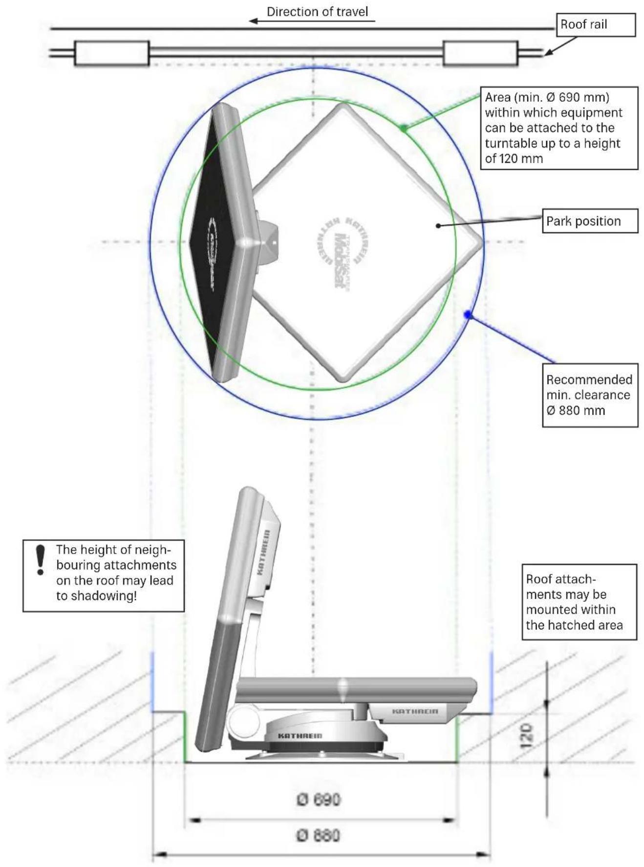
When selecting the installation position, take into account the range of movement of the turntable, 10.2 Dimensions (in mm), p.37. There must not be any attachments on the roof that would obstruct this range of movement (risk of collision). To be on the safe side, keep slightly more than the required area free. This allows for an easier installation and any subsequent dismantling.
▶ Choose an installation position on the roof that is as horizontal as possible or only slightly sloping, depending on the location of the vehicle, since roof inclinations greater than 5irc may lead to problems when searching for the satellite.
▶ To ensure secure adhesion, the height difference of the roof curve must not be more than 1 cm over a length of 2 m, as otherwise the gap between the roof and the mounting plate would be too great to be filled by the adhesive sealant.
As the vehicle is constantly subjected to vibration loads during travel, the roof below the antenna unit is also subject to significant loads. Please note, given the nature and capacity of your vehicle roof, that the weight of the antenna unit is approx. 14.5 kg, see the operating manual for the vehicle. If in doubt, consult a qualified specialist dealer or your vehicle's manufacturer.
The roof gland provides a watertight seal through which the three cables (2 x coaxial cable and power supply cable) are fed into the interior of the vehicle directly underneath the turntable. If you prefer a different method of laying the cables, you can run them out from the rear of the turntable via the channel provided in the mounting plate. The cables must then be run along the roof of the vehicle in a protective cable duct and through a separate roof gland HDZ 100 (neither of them are included in the scope of delivery).
The HDZ 100 roof gland is available as an accessory under part number 20410032 from specialist dealers.

Risk of material damage during transportation!
▶ Protect the positive wire (red) of the power supply cable by using a 15 A blade fuse.
▶ The fuse must be installed by a specialist.
▶ If the fuse is blown, replace it by a fuse of the same rating (15 A).
▶ Eliminate the cause of the fault.
5.1.4 Installing the Cable Gland and Mounting Plate

If you have previously used a Kathrein HDM 140/141 jointed tripod mast or another mast with a diameter of 34 mm, you can continue using the existing through hole in the roof.
Fig. A Fig. B
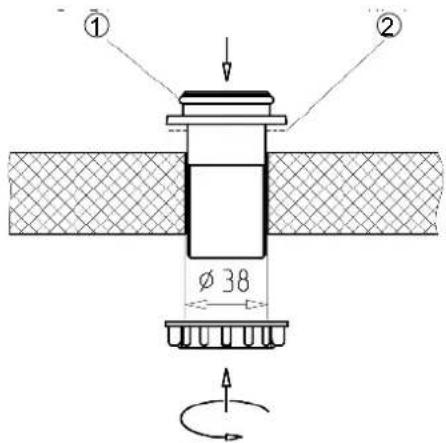
① O-ring
② Adhesive
natural_image
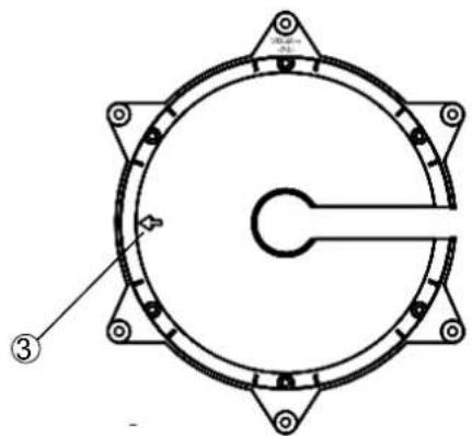
Technical diagram of a circular mechanical component with mounting holes and a central shaft (no text or symbols)③ Arrow in the direction of travel
- In the centre of the intended position of the turntable, drill the opening for the cable gland with a circular cutter of ∅ 38 mm.
- Deburr the hole with a round file or emery paper.
- Provisionally insert the roof duct into the drilled hole (Fig. A).
- Place the mounting plate on the roof of the vehicle, such that the centre hole is positioned centrally to the cable gland. The arrow symbol ③ must be visible from above and point forwards in the direction of travel of the vehicle (Fig. B).
- Mark the positions of the six fastening holes on the roof of the vehicle in a pitch circle.

The size of the holes and the choice of fastening screws to be used (not included) depend on the type and thickness of the materials used in the roof structure. If the roof panelling (plastic roofs) is sufficiently strong, it is recommended to always use round head screws, plain washers and self-locking nuts to secure the glued mounting plate.
- If the roof panel material is very thin and does not provide adequate holding power within the insulation material, through holes ( 5.5 mm) into the interior of the vehicle are required and galvanised M5 round head screws of sufficient length must be used.
Make sure that you use a sufficiently strong support that can withstand the bolt tensile forces (large plain washer or a complete reinforcing plate).
Fig. C
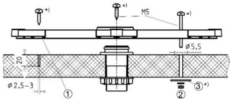
① Adhesive area between the two grooves
② Alternative roof fastening
③ Washer *)
*) Not included
- Create the holes necessary to secure the mounting plate (Fig. C).
-
In addition to the screwed connection, the mounting plate and roof duct must be bonded to the roof with adhesive and sealed. This is done using an adhesive sealant (e.g. DEKAsyl MS adhesive sealant), which is ideally suited for this purpose due to its broad range of adhesion. Please note the following points:
-
It is essential that you have carefully read through the safety data sheet for the adhesive sealant and the technical data sheet before you start working with the adhesive sealant!
- The prerequisite for good adhesive properties is a clean, dry and grease-free substrate. You should therefore clean the roof surface with a suitable cleaning agent within a circumference of 35cm around the drilled hole and allow the surface to dry thoroughly.
- If the surface is painted, ensure that the paint finish is sufficiently well bonded to the substrate.
-
If the coat of paint is already loose or peeling, it must be removed down to a stable layer in the area to which the adhesive will bond. If you have any doubts concerning the adhesive properties, consult a paint and lacquer specialist, or the manufacturer of your vehicle.
-
The procedure for gluing the mounting plate is as follows:
Fig. D

① Recess for cable
② Adhesive area between the two grooves
- Ensure before starting adhesive work that the processing temperature of materials to be glued and the adhesive sealant is between +5ircC and +35ircC . Prepare all necessary fastening elements and tools.
- Prepare the adhesive sealant in accordance with the instruction.
- Remove the roof duct (Fig. A) again and apply the adhesive sealant evenly to the underside of the roof duct flange.
- Insert the roof duct into the drilled hole and press it against the vehicle roof.
- Apply the adhesive sealant evenly to the underside of the mounting plate, completely covering the area within the circular groove (Fig. D). This area of the vehicle roof must be completely coated with adhesive in order to achieve the necessary bonding force.
- Place the mounting plate onto the roof of the vehicle, as you did previously when marking out the drilled holes. Make sure that the arrow on the mounting plate points forwards in the direction of travel of the vehicle. The fastening holes must be perfectly aligned with the prepared holes in the roof.
- Fasten the mounting plate in place with the prepared screws, evenly tightening six screws across the diagonals.

Risk of material damage due to applying too much force when tightening the screws!
The adhesive sealant used is capable of filling small gaps caused by the curvature of the vehicle roof. If you apply too much force when tightening the screws, the mounting plate could be bent.
▶ Tighten the screws carefully.
- Use a clean colourless cloth to remove any adhesive sealant that leaks out at the sides. Pay attention to the following:
\~ Do not use any cleaning agents or thinners containing solvents, as this could damage the adhesive sealant applied under the mounting plate.
\~ It is recommended to soak the cloth in acetone or MEK. Apply the cloth soaked in acetone or MEK to an inconspicuous area to make sure that it does not adversely affect or damage the surface.
\~ Use only cleansing paste and water to clean your hands. - Secure the cable gland from inside the vehicle by tightening the ribbed nut supplied (Fig. A).
- Note that the curing of the adhesive sealant depends on the ambient temperature and the humidity. Please refer the final strength the data sheet of your sealing adhesive. However, this need not restrict further installation work, since the mounting plate is held in place by the tightened screws.
5.1.5 Installation of the Turntable
Variant with cable gland underneath the turntable
- Feed the ends of the cables with the connectors as far as possible through the cable duct into the interior of the vehicle.
- Lift the turntable and place it carefully on the mounting plate in the direction of travel (see Fig. E). Do not step on the connectors or kink or crush the cables!
- The through holes on the turntable must be perfectly aligned with the threaded holes on the mounting plate. When lowering, make sure that the cables are fed through the cable gland and are not crushed.
- Apply a little adhesive sealant to the six threaded holes in the mounting plate and screw the fastening screws into the thread. Tighten the screws to a torque of 6 Nm.
- To prevent water vapour from inside the vehicle reaching the turntable through the roof duct, thread the three cables through the sealing gasket supplied, fold it and insert it into the roof duct until it reaches the stop (see Fig. E). Make sure that no tensile load is acting downwards on the sealing gasket as this can cause it to fall out in the course of time.
Fig. E
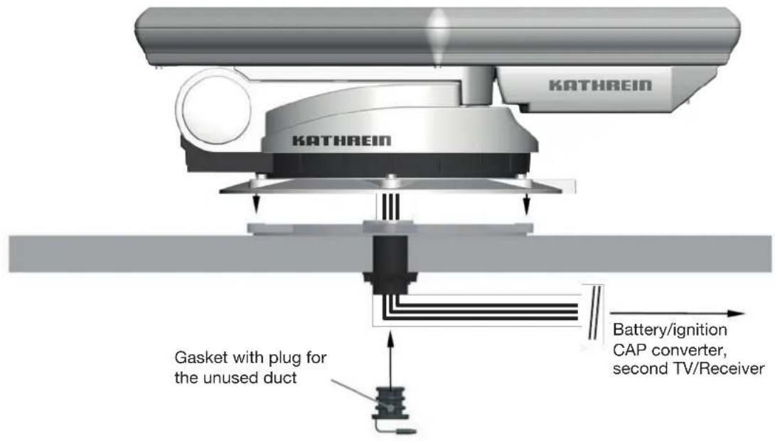
Version with external cable gland
The external roof duct is arranged such that it forms a watertight enclosure on the vehicle roof around the point where the three cables projecting from the turntable are connected to the two extension cables within the interior of the vehicle, and where if necessary they can be disconnected (see Fig. F).
- Arrange the cables in the cable duct when placing the turntable on to the mounting plate. Make sure that the cables are not crossed over and that they are taut so that they cannot be crushed.

Risk of material damage due to pulling the cables from the turntable!
▶ Do not try to pull the cables from the unit.
- Place the turntable carefully on the mounting plate. Make sure that the through holes on the turntable are perfectly aligned with the threaded holes on the mounting plate.
- Apply a little adhesive sealant to the six threaded holes in the mounting plate and screw the fastening screws into the thread. Tighten the screws to a torque of 6 Nm.
- When feeding the connecting cables through the HDZ 100 roof gland, make sure they are not crushed, kinked or damaged.
Fig. F

*) Not included! The HDZ 100 roof gland is available as an accessory under part number 20410032 from specialist dealers.
5.1.6 Installing the Turntable

The sequence of pictures shown illustrates all the necessary installation steps that are required to install the turntable and the pre-assembled flat antenna on the roof of the vehicle. However, follow the other detailed instructions in this installation and operating manual!
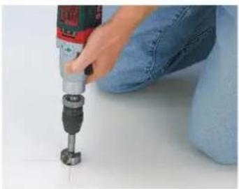
natural_image
Close-up of a hand using a power drill bit to press or install a screwdriver on a white surface (no text or symbols visible)-
Determine the installation location. Note the following:
-
Swing path of the system = ∅ 96 cm
- Drill a hole with ∅ 38 mm for the cable gland
- Deburr any sharp edges of the hole
See also 5.1.3 Selecting the Installation Location, p.13ff

natural_image
Person using a tool to apply black plastic components on a white surface, with other small parts nearby (no text or symbols visible)- Apply the sealing adhesive to the spigot of the roof duct. Insert the spigot into the hole and secure it from below with the knurled nut.

natural_image
Close-up of hands operating a white circular device with a black control panel (no visible text or symbols)- Unscrew the screws (x 6, 10 AF) from the mounting plate and remove the mounting plate.

natural_image
Product photo of a vacuum cleaner with attached fan and disc components (no visible text or symbols)- Place the turntable on prepared wooden supports to protect the roof of the vehicle.

natural_image
Hand holding a pen writing on a circular object, no visible text or symbols- Align the mounting plate with the arrow pointing in the direction of travel. The arrow is marked with ① at step 8 in the illustration.
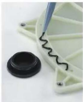
natural_image
Close-up of a mechanical component with a black wavy line being inserted, next to a small black circular base (no text or symbols visible)-
Apply the sealing adhesive in a wavy line between the two grooves and spread it with a spatula or similar.
-
Mark out and drill the six holes to secure the mounting plate (see 5.1.4 Installing the Cable Gland and Mounting Plate, p.14, Fig. C).

Risk of skin injuries!
▶ Avoid any skin contact with the adhesive sealant.
▶ Note the safety information of your adhesive.
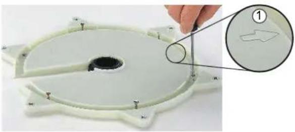
natural_image
Close-up of a white plastic component with a circular hole and multiple side supports, being cut by fingers (no text or symbols visible)- Place the mounting plate on the roof gland and secure it with the appropriate screws (choose screws according to thickness/structure of roof).

natural_image
Person using a pressure gauge to measure a white cake on a stand (no text or symbols visible)- Screw the turntable onto the mounting plate using the torque wrench.

Risk of material damage due to an inadmissible tightening torque!
If the torque is too high, the thread in the mounting plate can be destroyed. If the torque is too low, the screws can come loose due to vibrations.
▶ Comply with the tightening torque of 6 Nm.
- Make the electrical connections.
- Connect the CAP converter or alphatronics TV.
- Connect the turntable to the battery.
5.1.7 Laying the Cables and Connecting the Turntable

Risk of damage to cables from sharp edges and chafing points!
▶ Do not lay cables across sharp edges.
▶ Protect cables against possible chafing points.
- Connect the master coaxial cable (marked red) to the master control unit (suitable alphatronics SL TV set or CAP converter) and the slave coaxial cable to a second TV with a built-in satellite tuner or receiver (if available).

If you do not use a receiver, we recommend attaching the second slave coaxial cable nonetheless, in case you might need it at a later time.
- Lay the turntable power supply cable (3-pin plug) to the battery. If necessary, use the power supply extension cable.
- Connect the master coaxial cable to the IF INPUT socket at the rear of the master control unit (alphatronics SL TV set (with Kathrein control) or CAP converter). If necessary, use the coaxial extension cable.
- Make sure that each live cable leading to the individual units is sufficiently fuse-protected and was installed by an expert. Make sure that all fuses are intact. If the fuse blows, the source of the fault must first be eliminated. The fuse may only be replaced by a fuse with the same rating.

Risk of severe injuries due to cable fire!
▶ Do not remove or bypass the fuse in the cable.
- At the connecting point for the power cable, the voltage must not fall below 11.5 V even with a higher load. Otherwise optimum functioning can no longer be guaranteed.
- Only for motor homes: The third, green core of the connecting cable, marked "IGNITION", allows the connection to a circuit in the vehicle that is activated when the ignition key is turned and then carries a continuous 12 V supply voltage. This type of connection ensures that when the engine is started the antenna is automatically lowered into the park position (the receiver does not need to be turned on).

Note that the antenna can be lowered only when the supply voltage is present in addition to the ignition signal!
- Make sure that the 15 A blade fuse was expertly installed to the positive conductor (red) of the power supply cable.

Risk of malfunction and material damage due to reversed polarity!
When connecting the power cables, reversed polarity can lead to thermal overload and damage to components when the equipment is powered up. If the earth (-) of the ignition signal and the earth (-) of the vehicle battery for the turntable do not have the same potential, the automatic antenna lowering does not function!
▶ To ensure a sufficient power supply to the automatic turntable, connect the current-carrying wires (red, black) directly to the vehicle battery.
In order that the antenna is automatically lowered to the park position, connect the green wire to the ignition and the red and the black wire to the vehicle battery.
The blade fuse supplied must be connected between the positive pole of the battery and the red wire of the turntable.
For operation with two batteries, it is necessary to ensure that the ignition signal earth has the same potential as the vehicle battery earth for the turntable.
▶ When connecting the power cables (CAP converter, alphatronics TV set or turntable) to the vehicle electrical system, make sure that the poles (+ and -) are not reversed.
5.1.8 Functional Instructions for Connection to the On-board Power Supply
Under certain circumstances, problems can arise when the units are connected to different connecting sockets or circuits/earth potentials. If no others are available, it is recommended that you connect the connecting sockets for the alphatronics TV set, the receiver or the CAP converter to the same cable, see Fig. G. Check the power rating of the circuit used with respect to the intended application.
5.1.9 Connection Example for 12 V Battery Connection

flowchart
graph TD
    A["TV set 1 with satellite tuner"] --> B["Power supply cable"]
    C["TV set 2 with satellite tuner"] --> D["Slave coaxial cable"]
    D --> E["Master coaxial cable"]
    E --> F["UFZ 131* Wi-Fi Hotspot"]
    G["TV set 1 with satellite tuner"] --> H["Ignition"]
    I["TV set 2 with satellite tuner"] --> J["Slave coaxial cable"]
    K["HDS 50* separate control panel"] --> L["Master coaxial cable"]
    M["CAP Converter control unit"] --> N["Cap Control app* control & streaming"]
    O["12V"] --> P["Water meter"]
    Q["Mobile device"] --> R["Smartphone"]
    S["Computer monitor"] --> T["Smartphone"]
    U["Camera with seagulls"] --> V["Satellite"]

When operating with two batteries, ensure that the ground of the ignition signal is at the same potential as the ground of the supply battery for the turntable. potential as the earth of the supply battery for the turntable. Otherwise the automatic automatic lowering will not work! Do not reverse the polarity of the cables!

In order for the GPS data to be read and the antenna to automatically lower itself into the parking position, the green wire must be connected to the ignition and the red and black wires to the power supply.
5.2 Installation and Connection of the CAP Converter
5.2.1 Selection of a Suitable Installation Location

When choosing the installation location, bear in mind that the rear of the CAP converter should always be accessible. The CAP converter is equipped with a power saving circuit, which means that the unit does not need to be placed where it is visible. You can therefore fit the CAP converter out of sight in any location, e.g. on cupboard walls, side walls or the base of storage compartments.
The four screw sockets provided (see Preparing the CAP Converter for Installation, p. 24) allow you to place the CAP converter not only on a firm even surface but also to fix it there or mount it in other positions.
When choosing the installation location, take account of the following:
- The wall thickness of the installation surface must be at least 15 mm, as otherwise the screws will break through on the other side or damage the surface.
- Ensure that the cupboard or storage compartment in which the unit is housed is adequately ventilated, to prevent a build-up of heat. Carpet-covered walls are unsuitable for installation
- Take care when tightening the screws not to damage any cables or similar behind or in the wall
- The CAP converter is designed exclusively for installation in dry, interior locations.
- The cable lengths must be taken into account when choosing the installation location
- The connecting cables must be provided with strain reliefs
Ventilation
The heat generated within the CAP converter can be dissipated from all sides of the casing. When selecting the installation location, make sure that these sides are not obstructed or covered. If the unit is operated continuously with insufficient ventilation, this can negatively affect the length of its working life!
Maintain a clearance of at least 20 cm above and below the unit, 2 cm to either side and 5 cm behind and in front of it, to allow unobstructed dissipation of the heat generated.


Risk of material damage due to insufficient ventilation!
The unit monitors its own temperature in operation. Continuous operation at temperatures higher than the recommended operating temperature can cause premature failure of the unit as a result of insufficient ventilation. This does not constitute grounds for a claim under warranty/guarantee!
▶ Operate the CAP converter only at the recommended operating temperature.
Connections and fusing of the unit
All the connecting cables are connected at the rear of the CAP converter, see also 5.2.6, p. 27.
On the left-hand side of the CAP converter viewed from the front there is a fuse inserted from the outside. This fuse must be accessible even after the unit has been installed, so that it can easily be exchanged if required. For more information about the type of fuse, see the sticker on the CAP converter and the fuse itself.
5.2.2 Preparing the CAP Converter for Installation
Removing the blanking caps
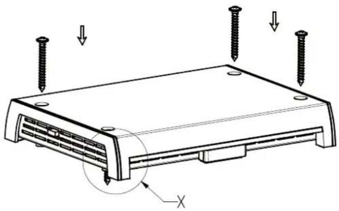
When the unit is delivered, the screw sockets are covered with blanking plugs. Push these out, using the screws supplied working upwards from below in the direction of arrow.

natural_image
Line drawing of a server rack with mounting holes and indicator lights (no text or symbols)Marking out the screw/drill points at the installation location
Use the diagram below for the intervals between screw/drill points:

5.2.3 Important Instructions for Installation

Danger to life due to high voltage!
The wood screws could make contact with electrically live parts and cause danger to life from electric shock.
▶ Do not use the wood screws included with the CAP converter to mount the CAP converter onto another electrical device (e.g. TV set).

Risk of material damage due to countersunk head screws!
▶ Under no circumstances use countersunk head screws for installation (see figure on the right).


Risk of malfunction and material damage due to overheating!
If the CAP converter is attached to another electrical device, e.g. a TV set, the temperature rise of each unit in operation can affect the other, thus causing overheating.
Before installing the CAP converter on another electrical device, check with the manufacturer of the device or in the documentation supplied with it whether this is permissible, and if so, what fittings (screws, etc.) are necessary or can be used.
Using other screws
If because of the installation location or factors associated with it, the screws supplied cannot be used, refer to the figure on the right when
selecting the screws to be used. The figure shows you the cross-section area of the screw sockets on the CAP converter. From this, it is possible to see the characteristics of the screws which can be inserted into the CAP converter support, e.g. diameter, screw head profiles etc.

5.2.4 Installing the CAP Converter on the Rear Panel of a TV Set

Danger to life due to high voltage!
If the screws penetrate too deeply into the TV set, they may damage it beyond repair and cause the risk of a fatal electric shock.
▶ Before starting any installation work, disconnect all the units concerned from the mains.
Before installing the CAP converter, check with the manufacturer of the device or in the documentation supplied with it whether this is permissible, and if so, what fittings (screws, etc.) are necessary or can be used.

Material damage and risk of injuries from overheating of the devices and fire!
▶ Under no circumstances install the CAP converter between a TV set and a wall support.
▶ Installation of the CAP converter on the rear panel of a TV set is permissible only if the TV set is resting on a stand that is attached in some other way.
For installation on the rear panel of a TV set, securing with two screws is sufficient. Before installing the CAP converter, pay attention to the following:
- The TV set must have one of the following hole patterns for wall mounting on its rear panel: 100 x 100; 100 x 200; 200 x 200 or 200 x 400. If this is not the case, a VESA adaptor plate can be obtained from a specialist dealer.
- Before installing the CAP converter it is essential you read the section Wall mounting (or the equivalent) in the user instructions for your TV set. This will tell you the screw diameters (M4, M6 or M8) and the permissible screw penetration depth.
5.2.5 Installing the CAP Converter

Risk of material damage from applying too much force when tightening the screws!
If you apply too much force when tightening the screws, you can damage the screw sockets and the CAP converter casing or any cables already attached to it.
▶ Tighten the screws carefully.
Example for mounting on wood:
natural_image
Technical line drawing of a device casing with screw holes and mounting points (no text or symbols)
5.2.6 Connecting the CAP converter

The CAP converter must not be connected to any supply voltage other than 10.5 to 15.5 V. The CAP converter's earth connection must be connected to the negative pole of the motor home or caravan battery. Isolate the on-board power supply (master switch "off" or disconnect the positive pole of the on-board power supply battery) before commencing the following work.
- Connect the master coaxial cable (coming from the turntable) to the "IF IN" F-socket on the rear of the CAP converter.
- Connect the "IF OUT" connection of the CAP converter and a receiver or TV set with integrated tuner with a coaxial cable.
- Connect the power cable supplied (depending on the power supply available in your motor home or caravan, either a 12 V supply or a 230 V supply via a power supply unit) to the "12V---2,0A" socket on the CAP converter.
- Check the connections before you reconnect the on-board power supply.
- For commissioning and more detailed information on additional operating functions, please consult the operating instructions part of this operating manual.
5.2.7 Connection Example for 12 V Battery Connection
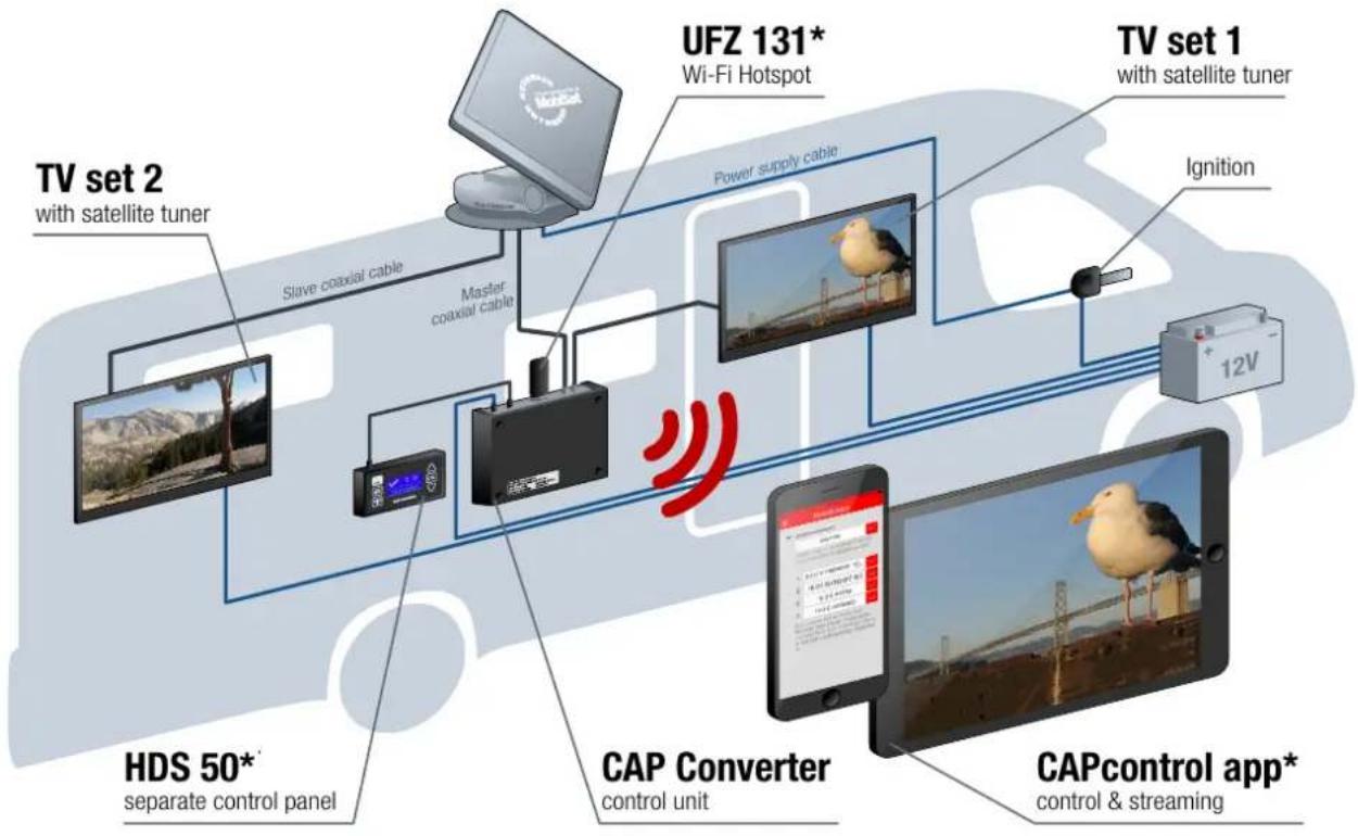
flowchart
graph TD
    A["TV set 1 with satellite tuner"] --> B["Power supply cable"]
    C["TV set 2 with satellite tuner"] --> D["Slave coaxial cable"]
    D --> E["Master coaxial cable"]
    E --> F["UFZ 131* Wi-Fi Hotspot"]
    F --> G["Cap Converter control unit"]
    G --> H["CAPcontrol app* control & streaming"]
    I["TV set 1 with satellite tuner"] --> J["Ignition"]
    J --> K["12V"]
    L["HDS 50* separate control panel"] --> M["Master coaxial cable"]
    M --> N["Master coaxial cable"]
    O["CAP converter"] --> P["Mobile device with signal icon"]
    Q["Control unit"] --> R["Mobile device with signal icon"]
5.3 Installation and Connection of the CTS 650-xx GPS
See operating instructions of the alphatronics TV set.
Connection Example for 12 V Battery Connection

flowchart
graph TD
    A["TV set 2 with satellite tuner"] --> B["Slave coaxial cable"]
    B --> C["Master coaxial cable"]
    C --> D["Power supply cable"]
    D --> E["12V battery"]
    E --> F["Capcontrol app* control & streaming"]
    G["UFZ 131* Wi-Fi Hotspot"] --> H["Ignition"]
    I["ALPHATRONICS CTS 650-xx GPS 19" / 22" / 24" TV with electronic control"] --> J["Mobile devices"]
    K["ICAM"] --> L["Smartphone"]
    M["Wi-Fi Hotspot"] --> N["Smartphone"]
    O["ICAM"] --> P["Smartphone"]
    Q["ICAM"] --> R["Smartphone"]
    S["ICAM"] --> T["Smartphone"]
    U["ICAM"] --> V["Smartphone"]
    W["ICAM"] --> X["Smartphone"]
    Y["ICAM"] --> Z["Smartphone"]
* Optional available accessories
6 Reception Range/Footprint
The footprint is the reception area on the earth that a satellite covers with its transmission beam (spot), within which satellite reception is possible. The transmission power is at its greatest in the centre of this spot – it becomes progressively weaker moving outwards.
You should preferably align your antenna to the position of the ASTRA satellite 19.2irc East (picture below left), EUTELSAT/HOTBIRD 13irc East (picture below right). The spots for these satellites are shown below.
The footprint in the left picture shows the entire area covered by the ASTRA satellite with all transponders.

natural_image
Two map-style regions showing European countries with shaded zones, no text or labels presentFig. H: ASTRA 19.2° East Fig. I: EUTELSAT/HOTBIRD 13° East
7 Dismantling for Servicing
If repairs to the system or individual components are necessary, contact your specialist dealer or our service centre (see address below).

Risk of injuries when opening the turntable!
▶ Do not open the turntable yourself.

Risk of material damage when cutting the cables!
▶ Do not cut the cables.
▶ Disconnect the cables projecting from the turntable from the cables laid within the interior of the vehicle at the designated cable junction (unplug the plug).
7.1 Dismantling the Turntable
- Move the turntable to the park position.
- Unscrew the six M6 screws which secure the turntable to the mounting plate.
- Place two wooden supports on the vehicle roof for protection.
- Place the turntable on the prepared wooden supports.
- Use the original packaging to ship the turntable.
- Seal the opening in the vehicle roof appropriately to protect against the ingress of moisture.
- If an HDZ 100 roof duct has been fitted and the equipment is then removed, seal the cable glands that are no longer used with the integral plugs.
⇒ The casing is watertight again.
7.2 Address of the Service Centre
Main factory repair centre
83224 Grassau, Germany
Phone: +49 8641 6998427
Fax: +49 8641 6998429
Email: service@css-grassau.de
More service partners under:
www.kathrein-ds.com
8 Polarisation Setting
8.1 About Polarisation Setting
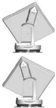
As supplied, the BAS 66 satellite antenna is mounted centrally on the turntable. In this position, the receiver still receives signals from satellites whose orbit position deviates by 15irc to 20irc longitude from the satellite antenna alignment (typical reception range).
If the orbit position of the satellites deviates by more than 15irc to 20irc longitude, the polarisation setting of the satellite antenna can be changed to improve reception. This is done by altering the mounting position of the satellite antenna.

We expressly draw attention to the fact that positioning the satellite antenna at a deviation of up to +15° or up to -15° from the centre position makes sense only if a satellite to the far west or the far east is actually preferred for reception. The same applies if you want to receive ASTRA 19.2°, for example, from a far west or far east position.
natural_image
Two identical mechanical components mounted on a base, no visible text or symbolsIf required, change the polarisation setting of the satellite antenna as follows:
- +15° if the satellite is more than between 15° and 20° west of the preferred reception range
- -15° if the satellite is more than between 15° and 20° east of the preferred reception range
The overview below shows the recommended mounting position for selected locations and typical satellites. This overview does not constitute a guarantee of reception of all channels from the satellites listed here.
| Country HOTBIRD | 13° East ASTRA 19.2° East | ASTRA 28.2° East | |
| Sweden -8 -7 -3 | |||
| Norway -8 -7 -3 | |||
| Germany -6 0 7 | |||
| France 2 8 13 | |||
| England | 4 6 | 11 | |
| Turkey | -25 | -19 | -12 |
| Southern Italy | -8 -3 9 | ||
| Southern Spain | 15 | 20 27 | |
| Portugal | 16 | 22 29 | |
| Belgium | -3 4 8 | ||
| Greece -19 | -13 | 0 | |
| Austria | -6 0 7 | ||
| Switzerland | -6 0 7 |

Longitude for the reception position
1) Deviation between the longitude of the desired reception area and the orbit position of the satellite
8.2 Safety Instructions

▶ Follow the general safety instructions; see 4 Safety Instructions and General Guidelines, p.7

Risk of material damage due to obstacles in the range of rotation or malfunction due to incorrect setting!
▶ Make sure that there are no obstacles in the range of rotation of the turntable.
▶ Do not alter the mounting position of the LNB yourself if you are not familiar with the setting operations. Contact a technician or try to find another suitable person.
8.3 Setting Operations
The following description assumes that the complete CAP unit has been properly assembled, installed and set up as described in the previous sections.
√ The CAP converter or the alphatronics TV set must be disconnected from the mains.
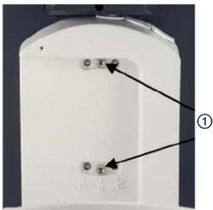
- Use the socket driver supplied (Torx, size 20) to slacken the securing screw of the clamp on the LNB.
- Rotate the LNB by the required degree value. The scale is located on the bottom of the LNB, see following figure.
- Tighten the fastening screw to a torque of 3,3 - 3,5 Nm.
- Leave the installation location.
- Reconnect the CAP converter or the alphatronics TV set to the power supply.
- Switch the CAP converter or the alphatronics TV set on using the on/off switch.
→ The system is ready for operation.
Fig. J
natural_image
Close-up of a white electronic device casing with two small components and an arrow pointing to a component (no text or symbols visible)View after installation -15°
Fig. K Fig. L Fig. M
View after installation +15° View after installation in the middle (standard)

natural_image
Close-up of three metallic dental crowns on a white surface (no text or symbols visible)
natural_image
Close-up of three metallic mechanical components on a white surface, no visible text or symbols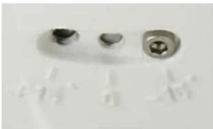
natural_image
Close-up of dental implant components (no visible text or symbols)
natural_image
3D rendering of a mechanical device with a tilted screen and base mount (no visible text or symbols)
natural_image
3D rendering of a mechanical component with a diamond-shaped base and central vertical shaft (no text or symbols visible)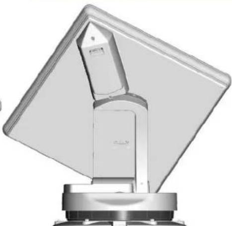
natural_image
3D rendering of a mechanical device with a tilted screen and base mount (no visible text or symbols)9 Manually Lowering the Antenna to Park Position

Risk of material damage due to a defect in the electronic controls!
If there is a defect in the electronic controls, the antenna cannot lower to the park position automatically. After some disassembly work, the satellite dish can be lowered to the park position manually. Before manually lowering the antenna, note the following:
▶ Drive to the nearest workshop at a moderate speed with the antenna extended, taking into account the increase of +80 cm in the vehicle height Driving to the nearest workshop is preferable to the manual lowering!
▶ Do not attempt to lower the antenna manually to the park position yourself if you are unfamiliar with the necessary repair work. Contact a technician or try to find another suitable person.
It is necessary to recalibrate the antenna in an authorised workshop after it has been manually lowered to the park position.
9.1 Safety Instructions

▶ Follow the general safety instructions; see Safety Instructions and General Guidelines, p. 7.

Risk of severe injuries when dismantling on the vehicle roof!
▶ Do not hold onto the antenna, as the rocker comes free during dismantling.

Risk of severe injuries due to moving or falling parts or crushing!
When removing the screws from the turntable, the rocker may suddenly come loose.
▶ During dismantling, always disconnect all the units from the power supply.
▶ Secure and support the antenna to prevent it from tipping over.
9.2 Manually Lowering the Turntable
natural_image
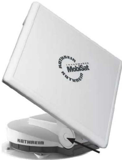
White KATHREIN transmemer MobiSat device with a circular logo on top, mounted on a base (no visible text or symbols beyond branding)- Using a narrow flat-bladed screwdriver, lever the plastic cap in the centre of the axis (see the arrow).
→ You can see an M8 hexagon head screw (WAF 13 mm).
- Remove the M8 hexagon head screw using a socket wrench (WAF 13 mm).
→ You can see another thread.
- Screw an M12 x 40 screw (minimum length: 40 mm) into this thread.
⇒ The rocker is pushed off the taper seating on the tapered shaft and the engagement is released.

Risk of material damage!
▶ Screw in the M12 screw only as far as to free the rocker from the engagement on the tapered shaft.
-
Tilt the antenna to the park position.
-
Remove the M12 screw.
→ You can put the rocker back on the tapered shaft.
-
Screw in the M8 screw and tighten it.
-
Replace the plastic cap.

Rocker displacement!
Loosening the rocker from the tapered shaft causes the rocker zero point position to be lost.
The rocker must be recalibrated by an authorised specialist dealer.
- Consult an authorised dealer.
10 Technical Data and Dimensions
10.1 Technical Data
| Type Unit CAP 650 GPS | ||
| Order no. 20310056 | ||
| LNB | VkHz | 2 switchable outputs: V/H (14/18) Low/High (0/22) |
| Supply voltage LNB V Vertical: 11.5 - 14 | Horizontal: 16 - 19 | |
| Input frequency GHz 10.70 - 12.75 | ||
| Output frequency MHz 950 - 1950/1100 - 2150 | ||
| Oscillator frequency (L. O.) GHz 9.75/10.60 | ||
| System quality (G/T) at 11.3/12.5 GHz dB/K | 13.3/13.7 | |
| Supply voltage (vehicle battery) | V | 10.5 - 15.5 |
| Power consumption from the 12 V electrical system: Inrush current Duration of the inrush current Satellite search TV reception Standby | A ms A mA | typ. 4, max. 5 approx. 5 typ. 3.5 typ. 1.2 < 30 |
| Power consumption from the CAP converter | mA | typ. 160 |
| Setting range Elevation Azimuth Skew | ° | 0 - 140 0 - 370 ±45 |
| Max. permissible wind speed during the reception | km/h 90 | |
| Weight of the turntable with flat antenna | kg 14.5 | |
| Packing unit/weight | pc./kg | 1/23.4 |
| Ignition signal | V | 10.5 - 15.5 |
| Search time for first satellite | s | typ. 10 - 60 |
| Search time for further satellites | s | typ. 2 - 30 |
| Start-up time LSM 1) | s | 2 - 15 |
1) LSM = Last Satellite Position
10.2 Dimensions (in mm)


11 Safety Instructions and General Guidelines
In the following operating manual we assume that the CAP converter or the alphatronics TV set and the turntable have been properly installed and connected, as described in Chapter 4, p. 7 and Chapter 5, p. 12. If you have not yet done so, read the safety instructions in this installation and operating manual and follow them when handling the CAP converter or the alphatronics TV set and the turntable!

Before setting up your satellite system, make sure that the location allows a free view to the satellite positions to the south and is not shadowed by trees or other obstructions.

Risk of malfunction and material damage from:
Overheating of the turntable motor!
If the turntable motor operates without interruption for longer than 20 minutes, it can cause overheating of the motor. None of the automatically initiated search procedures requires as much as 20 minutes of operation. Only repeated unsuccessful search procedures or manual overrides by the user can cause this limit to be exceeded.
▶ Do not let the turntable motor continuously run for longer than 20 minutes.
Absence of the ignition signal!
As soon as the ignition signal is no longer present at the turntable, it may automatically move to the last known satellite position. Precondition: The receiver is switched on and the turntable is supplied with a +12 V power supply.

12 CAP 650 GPS Operating Instructions
Beginning of the operating instruc- tions for
CAP 650 GPS
If, despite studying these operating instructions, you still have questions about getting started with the unit or using it correctly, or if unexpected problems occur, please contact your specialist dealer.
The Kathrein Technical Customer Support is also at your disposal.
Phone: +49 731 27090970
12.1 Installing the CAP Converter
√ The master coaxial cable is connected to the ANTENNA ② socket; see 5.2.6, p. 27.
- Connect the TV set to an TV/STB ① socket using a coaxial cable (not included).

Risk of malfunction!
▶ Do not interchange the cables.
- For installation of the 12 V connection cable (included) contact an authorised dealer.

12.2 Change of Location
To speed up the search after a change of location, enter the new location in the CAPcontrol app (available in the app store for Android and iOS) or in the external operating unit (HDS 50, order no. 20410070) 1) .
1) Optional available accessories
12.3 Operating the Turntable Using the External Push-button
12.3.1 Starting the Turntable
√ The turntable is in the park position.
▶ Press the push-button.
⇒ The turntable moves to the last satellite position.
12.3.2 Moving the Turntable to the Park Position.
√ The turntable is extended.
▶ Press the push-button.
⇒ The turntable lowers to the park position.
12.3.3 Performing a Reset
▶ Press the push-button for 5 seconds.
→ The turntable is being reset. The LED flashes 3 x green and 1 x red until the turntable is in the park position.
12.4 Updating Channel List and Software
12.4.1 Updating the Channel List
√ An FAT32 formatted USB flash drive is available for this task.
- On the USB flash drive create a kathrein folder with a capconverter subfolder.
- Download a channel.xml file with an up-to-date channel list from www.kathrein-ds.com
- Save the channel.xml file on the USB flash drive in the capconverter subfolder.
- Connect the USB flash drive to the CAP converter.
- Switch off the CAP converter using the on/off switch.
- Switch the CAP converter on again.
→ The channel list is loaded automatically when the CAP converter starts. The LED status shows whether the channel list has been successfully downloaded or whether there has been a problem, see 12.5 LED Status Display on the CAP Converter V2 - external Pushbutton, p.43
12.4.2 Preparing a software update
√ A FAT32-formatted USB stick is available.
- Download a country-specific zip file, e.g. "CAP-Konverter_Deutschland_08.19.zip" from www.kathrein-ds.com
- Open the downloaded zip file with a double click and execute the exe file with a double click.
- Click on the “...” button to select the FAT32-formatted USB stick that you want to use for the update.
- Confirm the selection with "OK".
- Click on the "Extract" button.
→ The required files are automatically unpacked to the corresponding folder structure on the USB stick.
12.4.3 Performing a software update
- Switch off the CAP converter at the power switch.
- Plug the USB stick into the USB port of the CAP converter.
- Keep the "Reset" button on the back of the CAP converter pressed and simultaneously switch on the CAP converter at the power switch.
→ During the update process the LED starts to light up yellow.
- Release the "Reset" button.
⇒ The update process lasts about 90 seconds. The successful update is indicated by fast "red-green-yellow" flashing. An error during the update is indicated by red flashing (see 12.5 LED Status Display on the CAP Converter V2 - external Pushbutton, p.43).
- After a successful update, switch off the CAP converter at the power switch, remove the USB stick and restart the CAP converter.

It is only possible to perform the update if the switch on the rear side of the CAP converter is pressed!
12.5 LED Status Display on the CAP Converter
V2 - external Pushbutton
| Function | LED Colour Signal | Description | |
| Error Red | LED flashes 1x for 0.5 sec, then pauses for 2 sec No connection to CAP/HDS | ||
| LED flashes 2x for 0.5 sec, then pauses for 2 sec Satellite not found | |||
| LED flashes 3x for 0.5 sec, then pauses for 2 sec Ignition is active | |||
| LED flashes 4x for 0.5 sec, then pauses for 2 sec Turntable is blocked | |||
| LED flashes 5x for 0.5 sec, then pauses for 2 sec Operating voltage too low | |||
| LED flashes 6x for 0.5 sec, then pauses for 2 sec Temperature warning | |||
| LED flashes 7x for 0.5 sec, then pauses for 2 sec Channel list incorrect | |||
| LED flashes 8x for 0.5 sec, then pauses for 2 sec CAP software not up to date | |||
| LED flashes 9x for 0.5 sec, then pauses for 2 sec CAP requires calibration |

To return the CAP converter to normal operation:
- Check the cause of error.
- Press the pushbutton once to acknowledge the error so that the CAP converter can return to normal operation.
| Normal operation | Green | LED flashes slowly CAP is in the park position | |
| LED flashes 3x, followed by a short pause | CAP is moving to the park position. | ||
| LED flashes quickly | CAP is searching for a satellite signal | ||
| LED is permanently on Satellite found | |||
| Red LED is permanently on Standby | |||
| Green-red LED flashes quickly 3x green and 1x red | CAP is reset and moves to the park position | ||
| USB update | Yellow 1) | LED is permanently on Downloading data from USB | |
| Red-green-yellow | LED flashes quickly | Update successful | |
| Red | LED flashes 1x for 0.5 sec, then pauses for 1.5 sec | Data carrier not found | |
| LED flashes 2x for 0.5 sec, then pauses for 1.5 sec | Folder structure/update file not found | ||
| LED flashes 3x for 0.5 sec, then pauses for 1.5 sec | Invalid update file | ||
| LED flashes 4x for 0.5 sec, then pauses for 1.5 sec | Saving update file failed |
1) On the external push-button, the red and the green LEDs are on at the same time
12.6 Possible Malfunctions
12.6.1 Error Indication on the CAP Converter/External Push-button
See 12.5 LED Status Display on the CAP Converter V2 - external Pushbutton, p.43
12.6.2 Other Problems

If a satellite cannot be found, make sure that the sequence of the satellite positions in your receiver corresponds to the sequence of the satellite positions in the CAP converter.

If there is a connection problem between the CAP converter and the turntable, check the cabling (see 5.2.7 Connection Example for 12 V Battery Connection, p.27).
13 Addresses
13.1 Service and Support
Customer Support
Eiselauer Weg 13
89081 Ulm, Germany
Phone: +49 731 270 909 70
Email: support@kathrein-ds.com
Business Hours:
Monday to Thursday 8 am to 5 pm | Friday 8 am to 4 pm (CET)
13.2 Factory Repair Centre
83224 Grassau, Germany
Phone: +49 8641 699 84 27
Email: service@css-grassau.de
13.3 Service Partners
You can find service partners under www.kathrein-ds.com.
14 Disposal

Electronic equipment
Electronic equipment is not domestic waste – in accordance with directive 2012/19/EC OF THE EUROPEAN PARLIAMENT AND THE COUNCIL dated 04th July 2012 concerning used electrical and electronic appliances, it must be dis- posed of properly. At the end of its service life, take this unit for disposal at a designated public collection point.
15 Simplified EU Declaration of Conformity
Hereby, KATHREIN Digital Systems GmbH declares that the radio equipment types HDP 650 GPS, BN: 20410083 and CAP 650 GPS, BN: 20310055 are in compliance with Directive 2014/53/EU. The full text of the EU declaration of conformity are available at the following internet address: www.kathrein-ds.com
16 Optional accessories
LCD 89 (Order No. 21510004)
Always use the supplied extension cable to extend the coaxial cables. If the enclosed extension cable is not sufficient, use the LCD 89 antenna cable with the FM-Mini-TD QM5.0 (092500004) F compression socket from KATHREIN Digital Systems.
HDS 50 (Order No. 20410070)
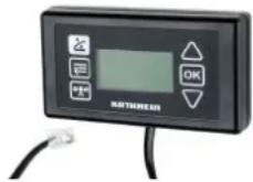
The external HDS 50 control unit enables you to operate the turntables easily and conveniently without having to switch on a receiver or TV set. Selecting a satellite and lowering the turntable to the parking position are examples of the functions that can be called up via an intuitively structured menu. An LC display provides the necessary overview.
HDS 42 (Order No. 2040000006)
The HDS 42 is a master/slave switch and is connected between a receiver-independent CAP turntable and the HDS 166 antenna set. It automatically passes on the received satellite signal without having to reconnect the coaxial cable on the TV set.
HDZ 100 (Order No. 20410032)
The HDZ 100 is a cable interface installed on the caravan roof to be used with the camping satellite antenna systems of the CAP series. The protective housing accommodates up to two RF cables and one power cable. The cables can either be run underneath the HDZ 100 housing into the car interior or out of the housing and onto the car roof.
UFZ 132 (BN: 204500005)
You can use the UFZ 132 USB/Wi-Fi adapter, in conjunction with the free CAPcontrol app, to make settings on your turntable and control unit and to play live TV/radio on your mobile device (smartphone, tablet, notebook). The USB/Wi-Fi adapter is plugged into the CAP converter.
HDS 52 (Order No. 20410079)
The CI-BUS adapter enables you to operate your Kathrein satellite antenna system of the CAP series with the vehicle-specific control panel of your motorhome/caravan. Please contact your vehicle manufacturer for further information.
12 V Power Supply Unit (Order No. 1683660)
For connection to 230 V sockets. The adapter cable (Order no. 197500004) is also required. You can order this plug-in power supply unit from our factory repair centre:
CSS Caravan-Sat-Service-GmbH
83224 Grassau, Germany
Phone: +49 8641 69984-27
Internet: http://www.css-grassau.de




17 Connection of the current-carrying cables
Important notice!
Valid for all available CAP/HDP turntables

ATTENTION
Material damage and malfunction due to reversed polarity!
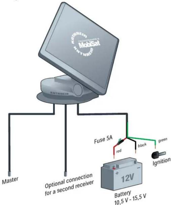
When connecting the power cables, reversed polarity can lead to thermal overload and damage to components when the equipment is powered up. If the earth (-) of the ignition signal and the earth (-) of the vehicle battery for the turntable do not have the same potential, the automatic antenna lowering does not function!
▶ To provide sufficient power supply for the automatic turntable, make sure to connect the current-carrying cables (red, black) directly to the vehicle battery.
For the automatic antenna lowering, connect the green cable to the ignition and the red and the black cable to the vehicle battery.
▶ Connect the fuse (included in the scope of delivery) between the positive pole of the battery and the red cable of the turntable.
For operation with two batteries, make sure that the earth of the ignition signal has the same potential as the earth of the vehicle battery for the turntable.
When connecting the power cables (CAP converter and turntable) to the vehicle electrical system, make sure that the poles (+ and -) are not reversed.
To be able to read the GPS data from the CAP turntable, you have to connect the green cable to the ignition and the red and black cable to the vehicle battery.


- Contents
- CAP 650 GPS Operating Instructions 40
- General
- Company address
- Intended Use
- Safety Instructions and General Guidelines
- Danger to life from electric shock when touching electrical installations!
- Risk of severe injuries during installation/repairs/dismantling on the vehicle roof!
- Risk of severe injuries due to moving parts, especially risk of crushing!
- Risk of damage when the permissible wind speeds or vehicle speeds are exceeded!
- Risk of accidents due to collision of the antenna with objects!
- Risk of malfunction or material damage due to operation outside the permissible temperature range!
- Proper installation and safety
- The system may be installed only by qualified specialist personnel!
- Essential information
- Adhesive sealant
- Risk of material damage due to improper use of the adhesive sealant!
- Road Traffic Licensing Regulations (StVZO)
- Cables
- Risk of smouldering fire!
- Trip hazard due to cables!
- Risk of parasitic induction or interference emissions!
- Risk of material damage due to reversed polarity!
- Supply voltage, fusing
- Risk of severe injuries due to cable fire!
- Risk of material damage due to the absence of a blade fuse in the cable!
- Checks before commencing a journey
- Antenna in the park position whilst driving
- Important note!
- Setting the satellite position in the CAP converter
- Installation and Connection
- Installing and Connecting the Turntable
- Required Tools and Equipment
- Unpacking and Preparing
- Risk of material damage during transportation!
- Unpacking the turntable
- Preparing the turntable
- Selecting the Installation Location
- Installing the Cable Gland and Mounting Plate
- Risk of material damage due to applying too much force when tightening the screws!
- Installation of the Turntable
- Variant with cable gland underneath the turntable
- Version with external cable gland
- Risk of material damage due to pulling the cables from the turntable!
- Installing the Turntable
- Risk of skin injuries!
- Risk of material damage due to an inadmissible tightening torque!
- Laying the Cables and Connecting the Turntable
- Risk of damage to cables from sharp edges and chafing points!
- Risk of malfunction and material damage due to reversed polarity!
- Functional Instructions for Connection to the On-board Power Supply
- Connection Example for 12 V Battery Connection
- Installation and Connection of the CAP Converter
- Selection of a Suitable Installation Location
- Ventilation
- Risk of material damage due to insufficient ventilation!
- Connections and fusing of the unit
- Preparing the CAP Converter for Installation
- Removing the blanking caps
- Marking out the screw/drill points at the installation location
- Important Instructions for Installation
- Danger to life due to high voltage!
- Risk of material damage due to countersunk head screws!
- Risk of malfunction and material damage due to overheating!
- Using other screws
- Installing the CAP Converter on the Rear Panel of a TV Set
- Material damage and risk of injuries from overheating of the devices and fire!
- Installing the CAP Converter
- Risk of material damage from applying too much force when tightening the screws!
- Connecting the CAP converter
- Connection Example for 12 V Battery Connection
- Installation and Connection of the CTS 650-xx GPS
- Reception Range/Footprint
- Dismantling for Servicing
- Risk of injuries when opening the turntable!
- Risk of material damage when cutting the cables!
- Dismantling the Turntable
- Address of the Service Centre
- Main factory repair centre
- Polarisation Setting
- About Polarisation Setting
- Safety Instructions
- Setting Operations
- Manually Lowering the Antenna to Park Position
- Risk of material damage due to a defect in the electronic controls!
- Safety Instructions
- Risk of severe injuries when dismantling on the vehicle roof!
- Risk of severe injuries due to moving or falling parts or crushing!
- Manually Lowering the Turntable
- Risk of material damage!
- Rocker displacement!
- Technical Data and Dimensions
- Technical Data
- Dimensions (in mm)
- Safety Instructions and General Guidelines
- Risk of malfunction and material damage from:
- Overheating of the turntable motor!
- Absence of the ignition signal!
- CAP 650 GPS Operating Instructions
- Beginning of the operating instruc- tions for
- CAP 650 GPS
- Installing the CAP Converter
- Risk of malfunction!
- Change of Location
- Operating the Turntable Using the External Push-button
- Starting the Turntable
- Moving the Turntable to the Park Position.
- Performing a Reset
- Updating Channel List and Software
- Updating the Channel List
- Preparing a software update
- Performing a software update
- LED Status Display on the CAP Converter
- V2 - external Pushbutton
- To return the CAP converter to normal operation:
- Possible Malfunctions
- Error Indication on the CAP Converter/External Push-button
- Other Problems
- Addresses
- Service and Support
- Factory Repair Centre
- Service Partners
- Disposal
- Electronic equipment
- Simplified EU Declaration of Conformity
- Optional accessories
- LCD 89 (Order No. 21510004)
- HDS 50 (Order No. 20410070)
- HDS 42 (Order No. 2040000006)
- HDZ 100 (Order No. 20410032)
- UFZ 132 (BN: 204500005)
- HDS 52 (Order No. 20410079)
- V Power Supply Unit (Order No. 1683660)
- Connection of the current-carrying cables
- Important notice!
- Valid for all available CAP/HDP turntables
- ATTENTION
Brand : KATHREIN
Model : HDP 650 GPS
Category : Satellite antenna