Multiweld 400T - Welding machine GYS - Free user manual and instructions
Find the device manual for free Multiweld 400T GYS in PDF.
Questions des utilisateurs sur Multiweld 400T GYS
0 question sur cet appareil. Repondez a celles que vous connaissez ou posez la votre.
Poser une nouvelle question sur cet appareil
Download the instructions for your Welding machine in PDF format for free! Find your manual Multiweld 400T - GYS and take your electronic device back in hand. On this page are published all the documents necessary for the use of your device. Multiweld 400T by GYS.
USER MANUAL Multiweld 400T GYS
INSTALLATION – FONCTIONNEMENT PRODUIT
INTERFACE HOMME MACHINE (IHM) (FIG. VI)
ANOMALIES, CAUSES, REMÈDES
GENERAL INSTRUCTIONS Read and understand the following safety recommendations before using or servicing the unit. Any change or servicing that is not specied in the instruction manual must not be undertaken. The manufacturer is not liable for any injury or damage due to non-compliance with the instructions featured in this manual.In the event of problems or uncertainty, please consult a qualied person to handle the inspection properly. ENVIRONMENT This equipment must only be used for welding operations in accordance with the limits indicated on the descriptive panel and/or in the user manual. The operator must respect the safety precautions that apply to this type of welding. In case of inedaquate or unsafe use, the manufacturer cannot be held liable for damage or injury. This equipment must be used and stored in a place protected from dust, acid or any other corrosive agent. Operate the machine in an open, or well-ventilated area.Operating temperature:Use between -10 and +40°C (+14 and +104°F).Store between -20 and +55°C (-4 and 131°F).Air humidity:Lower or equal to 50% at 40°C (104°F).Lower or equal to 90% at 20°C (68°F).Altitude:Up to 1000 meters above sea level (3280 feet).
PROTECTION OF THE INDIVIDUALS
Arc welding can be dangerous and can cause serious and even fatal injuries. Welding exposes the user to dangerous heat, arc rays, electromagnetic elds, noise, gas fumes, and electrical shocks. People wearing pacemakers are advised to consult with their doctor before using this device.To protect oneself as well as the other, ensure the following safety precautions are taken:In order to protect you from burns and radiations, wear clothing without cus. These clothes must be insulated, dry, reproof and in good condition, and cover the whole body.Wear protective gloves which guarantee electrical and thermal insulation. Use sucient welding protective gear for the whole body: hood, gloves, jacket, trousers... (varies depending on the application/operation). Protect the eyes during cleaning operations. Do not operate whilst wearing contact lenses.It may be necessary to install reproof welding curtains to protect the area against arc rays, weld spatters and sparks.Inform the people around the working area to never look at the arc nor the molten metal, and to wear protective clothes.Ensure ear protection is worn by the operator if the work exceeds the authorised noise limit (the same applies to any person in the welding area).Stay away from moving parts (e.g. engine, fan...) with hands, hair, clothes etc...Never remove the safety covers from the cooling unit when the machine is plugged in - The manufacturer is not responsible for any accident or injury that happens as a result of not following these safety precautions.The pieces that have just been welded are hot and may cause burns when manipulated. During maintenance work on the torch or the electrode holder, you should make sure it’s cold enough and wait at least 10 minutes before any intervention. The cooling unit must be on when using a water cooled torch in order to ensure that the liquid does not cause any burns.ALWAYS ensure the working area is left as safe and secure as possible to prevent damage or accidents.
WELDING FUMES AND GAS
The fumes, gases and dust produced during welding are hazardous. It is mandatory to ensure adequate ventilation and/or extraction to keep fumes and gases away from the work area. An air fed helmet is recommended in cases of insucient air supply in the workplace.Check that the air intake is in compliance with safety standards Care must be taken when welding in small areas, and the operator will need supervision from a safe distance. Welding certain pieces of metal containing lead, cadmium, zinc, mercury or beryllium can be extremely toxic. The user will also need to degrease the14
workpiece before welding. Gas cylinders must be stored in an open or ventilated area. The cylinders must be in a vertical position secured to a support or trolley. Do not weld in areas where grease or paint are stored.
FIRE AND EXPLOSIONS RISKS
Protect the entire welding area. Compressed gas containers and other inammable material must be moved to a minimum safe distance of 11 meters. A re extinguisher must be readily available. Be careful of spatter and sparks, even through cracks. It can be the source of a re or an explosion. Keep people, ammable objects and containers under pressure at a safe distance. Welding of sealed containers or closed pipes should not be undertaken, and if opened, the operator must remove any inammable or explosive materials (oil, petrol, gas...). Grinding operations should not be directed towards the device itself, the power supply or any ammable materials. GAS BOTTLE Gas leaking from the cylinder can lead to suocation if present in high concentrations around the work area. Transport must be done safely: Cylinders closed and product o. Always keep cylinders in an upright position securely chained to a xed support or trolley. Close the bottle after any welding operation. Be wary of temperature changes or exposure to sunlight. Cylinders should be located away from areas where they may be struck or subjected to physical damage. Always keep gas bottles at a safe distance from arc welding or cutting operations, and any source of heat, sparks or ames. Be careful when opening the valve on the gas bottle, it is necessary to remove the tip of the valve and make sure the gas meets your welding requirements. ELECTRIC SAFETY The machine must be connected to an earthed electrical supply. Use the recommended fuse size. An electrical discharge can directly or indirectly cause serious or deadly accidents. Do not touch any live part of the machine (inside or outside) when it is plugged in (Torches, earth cable, cables, electrodes) because they are connected to the welding circuit. Before opening the device, it is imperative to disconnect it from the mains and wait 2 minutes, so that all the capacitors are discharged. Do not touch the torch or electrode holder and earth clamp at the same time. Damaged cables and torches must be changed by a qualied and skilled professional. Make sure that the cable cross section is adequate with the usage (extensions and welding cables). Always wear dry clothes in good condition, in order to be insulated from the electrical circuit. Wear insulating shoes, regardless of the environment in which you work in. EMC CLASSIFICATION These Class A devices are not intended to be used on a residential site where the electric current is supplied by the public network, with a low voltage power supply. There may be potential diculties in ensuring electromagnetic compatibility on these sites, because of the interferences, as well as radio frequencies. This equipment complies with the IEC 61000-3-11 standard. This equipment does not comply with IEC 61000-3-12 and is intended to be connected to private low-voltage systems interfacing with the public supply only at the medium- or high-voltage level. On a public low-voltage power grid, it is the responsibility of the installer or user of the device to ensure, by checking with the operator of the distribution network, which device can be connected. ELECTROMAGNETIC INTERFERENCES The electric currents owing through a conductor cause electrical and magnetic elds (EMF). The welding current generates an EMF eld around the welding circuit and the welding equipment. The EMF elds may disrupt some medical implants, such as pacemakers. Protection measures should be taken for people wearing medical implants. For example, access restrictions for passers-by or an individual risk evaluation for the welders. All welders should take the following precautions in order to minimise exposure to the electromagnetic elds (EMF) generated by the welding circuit::15
- keep your head and torso as far as possible from the welding circuit;
- never enroll the cables around your body;
- never position your body between the welding cables. Hold both welding cables on the same side of your body;
- connect the earth clamp as close as possible to the area being welded;
- do not work too close to, do not lean and do not sit on the welding machine
- do not weld when you’re carrying the welding machine or its wire feeder. People wearing pacemakers are advised to consult their doctor before using this device. Exposure to electromagnetic elds while welding may have other health eects which are not yet known. RECOMMANDATIONS TO ASSES THE AREA AND WELDING INSTALLATION Overview The user is responsible for installing and using the arc welding equipment in accordance with the manufacturer’s instructions. If electromagnetic disturbances are detected, it is the responsibility of the user of the arc welding equipment to resolve the situation with the manufacturer’s technical assistance. In some cases, this remedial action may be as simple as earthing the welding circuit. In other cases, it may be necessary to construct an electromagnetic shield around the welding power source and around the entire piece by tting input lters. In all cases, electromagnetic interferences must be reduced until they are no longer bothersome. Welding area assessment Before installing the machine, the user must evaluate the possible electromagnetic problems that may arise in the area where the installation is planned. In particular, it should consider the following: a) the presence of other power cables (power supply cables, telephone cables, command cable, etc...)above, below and on the sides of the arc welding machine. b) television transmitters and receivers ; c) computers and other hardware; d) critical safety equipment such as industrial machine protections; e) the health and safety of the people in the area such as people with pacemakers or hearing aids; f) calibration and measuring equipment g) the isolation of the equipment from other machinery. The user will have to make sure that the devices and equipments that are in the same room are compatible with each other. This may require extra precautions; h) make sure of the exact hour when the welding and/or other operations will take place. The surface of the area to be considered around the device depends on the the building’s structure and other activities that take place there. The area taken in consideration can be larger than the limits determined by the companies. Welding area assessment Besides the welding area, the assessment of the arc welding systems intallation itself can be used to identify and resolve cases of disturbances. The assessment of emissions must include in situ measurements as specied in Article 10 of CISPR 11. In situ measurements can also be used to conrm the eectiveness of mitigation measures. RECOMMENDATION ON METHODS OF ELECTROMAGNETIC EMISSIONS REDUCTION a. National power grid : The arc welding machine must be connected to the national power grid in accordance with the manufacturer’s recommendation. If interferences occur, it may be necessary to take additional preventive measures such as the ltering of the power suplly network. Consideration should be given to shielding the power supply cable in a metal conduit. It is necessary to ensure the shielding’s electrical continuity along the cable’s entire length. The shielding should be connected to the welding current’s source to ensure good electrical contact between the conduct and the casing of the welding current source. b. Maintenance of the arc welding equipment : The arc welding machine should be be submitted to a routine maintenance check according to the manufacturer’s recommendations. All accesses, service doors and covers should be closed and properly locked when the arc welding equipment is on. The arc welding equipment must not be modied in any way, except for the changes and settings outlined in the manufacturer’s instructions. The spark gap of the arc start and arc stabilization devices must be adjusted and maintained according to the manufacturer’s recommendations. c. Welding cables : Cables must be as short as possible, close to each other and close to the ground, if not on the ground. d. Electrical bonding : consideration shoud be given to bonding all metal objects in the surrounding area. However, metal objects connected to the workpiece increase the risk of electric shock if the operator touches both these metal elements and the electrode. It is necessary to insulate the operator from such metal objects. e. Earthing of the welded part : When the part is not earthed - due to electrical safety reasons or because of its size and its location (which is the case with ship hulls or metallic building structures), the earthing of the part can, in some cases but not systematically, reduce emissions It is preferable to avoid the earthing of parts that could increase the risk of injury to the users or damage other electrical equipment. If necessary, it is appropriate that the earthing of the part is done directly, but in some countries that do not allow such a direct connection, it is appropriate that the connection is made with a capacitor selected according to national regulations.16
f. Protection and plating : The selective protection and plating of other cables and devices in the area can reduce perturbation issues. The protection of the entire welding area can be considered for specic situations. TRANSPORT AND TRANSIT OF THE WELDING MACHINE Do not use the cables or torch to move the machine. The welding equipment must be moved in an upright position.Do not place/carry the unit over people or objects. Never lift the machine while there is a gas cylinder on the support shelf. A clear path is available when moving the item. The removal of the wire reel from the machine is recommended before undertaking any lifting operation. EQUIPMENT INSTALLATION
- Put the machine on the oor (maximum incline of 10°.)• Ensure the work area has sucient ventillation for welding, and that there is easy access to the control panel.• The machine must not be used in an area with conductive metal dusts. • The machine must be placed in a sheltered area away from rain or direct sunlight.• The MULTIWELD 250T/320T/400T protection level is IP21, which means :- Protection against acess to dangerous parts from solid bodies of a ≥12.5mm diameter and,- Protection against vertically falling drops.• The MULTIWELD FV 220M protection level is IP23, which means :- Protection against acess to dangerous parts from solid bodies of a ≥12.5mm diameter and,- Protection against the rain inclined at 60° towards the vertical.These devices can be used outside in accordance with the IP23 protection index.The power cables, extensions and welding cables must be fully uncoiled to prevent overheating.The manufacturer does not incur any responsability regarding damages to both objects and persons that result from an incorrect and/or dangerous use of the machine.Stray welding currents/voltages may destroy earth conductors, damage electrical equipment or cause components to warm up which may cause a re. - All welding connections must be rmly secured, check regularly !- Check that the metal piece xation is strong and without any electrical problems !- Attach or hang all the electrically conductive elements,such as the trolley in order to insulate them. - Do not place any electrical equipment such as drills on top of the welding machine without insulating them !- Always place welding torches or electrodes holders on an insulated surface when they’re not in use ! MAINTENANCE / RECOMMENDATIONS
- Maintenance should only be carried out by a qualied person. Annual maintenance is recommended.• Ensure the machine is unplugged from the mains, and wait for two minutes before carrying out maintenance work. DANGER High Voltage and Currents inside the machine.• Remove the casing 2 or 3 times a year to remove any excess dust. Take this opportunity to have the electrical connections checked by a qualied person, with an insulated tool.• Regularly check the condition of the power supply cable. If the power cable is damaged, it must be replaced by the manufacturer, its after sales service or an equally qualied person.• Ensure the ventilation holes of the device are not blocked to allow adequate air circulation.• Do not use this equipment to thaw pipes, to charge batteries, or to start any engine.
INSTALLATION – PRODUCT OPERATION
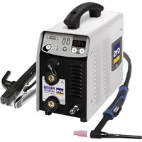
Only qualied personnel authorized by the manufacturer should perform the installation of the cutting equipment. During set up, the operator must ensure that the machine is unplugged. Connecting generators in a series or a parallel circuit is forbidden. It is recommended to use the welding cables supplied with the unit in order to obtain the optimum product settings. DESCRIPTION Thank you for chosing this machine. To get the best use from your machine, please read the following carefully : The MULTIWELD range are semi-automatic MIG/MAG, MMA and ux cored wire welding stations. They are manual settings ma- chine, with the help of the table printed on the product. They are recommended for welding steel, stainless steel and aluminium. POWER SUPPLY
- The MULTIWELD 250T/320T is tted with a 16A socket type EN 60309-1 which must be connected to a three-phase 400V (50 - 60 Hz) power supply tted with four wires and one earthed neutral.17
- The MULTIWELD 400T is tted with a 32A socket type EN 60309-1 which must be connected to a three-phase 400V (50 - 60 Hz) power supply tted with four wires and one earthed neutral.
- The MULTIWELD FV 220M is supplied with a 16 A CEE7/7 plug and may only be used in a single-phase 230 V (50 - 60 Hz) three- wire electrical installation with a grounded neutral conductor. This product, equipped with a «Flexible Voltage» system, can be used on an earthed electrical installation between 110V and 230V (50 - 60Hz). The absorbed eective current (I1e) is displayed on the machine, for optimal use. Check that the power supply and its protection (fuse and/or circuit breaker) are compatible with the current needed by the machine. In some countries, it may be necessary to change the plug to allow the use at maximum settings.
- The MULTIWELD FV 220M is equipped with the Protect 400 function (P400): the device switches to protection (protection light ashes) if the supply voltage is higher than 265V. Normal operation resumes as soon as the supply voltage returns to its nominal range.
USE WITH EXTENSION CABLES
All extension cables must have an adequate size and section, relative to the machine’s voltage. Use an extension that complies with national safety regulations.Input Voltage Section of extension cableMULTIWELD 400T400 V - 3~4 mm²MULTIWELD 250T/320T2.5 mm²MULTIWELD FV 220M230 V - 1~110 V - 1~ DEVICE PRESENTATION (FIG. I) 1- Reel support 9- Gas connector2- Back cable support 10- On/o switch3- Digital displays 11- Power supply cable4- Adjustement of welding settings 12- Bottle support (max 1 x 10m bottle)5- European standard torch connection 13- Plug 36V DC for gas preheater6- Polarity reversal cable Storage area (220M)7- Earth clamp connector Accessory box (400T)8- Torch support 15- Wire feed / gas purge switch16- Post-Gas switch CONTROL BOARD MMI (FIG. VI)
Overheat/Overcurrent indicator (250T/320T/400T)Overheat/Overcurrent indicator/P400 (FV 220M)7- MIG function indicator2- Voltage display 8- 2T/4T function switch button3- Current and wire speed display 9- MIG/MMA switch button4- Current indicator 10- Welding arc dynamic adjustment
5- Wire speed indicator 11- Wire speed adjustment (MIG) / current setting adjustment (MMA)
6- MMA function indicator 12- Voltage setting adjustment
SWITCHING ON The ON/OFF switch is located at the back of the machine. Turn the switch on the «I» position to start the generator. This switch must not be turned o (to «O») while welding. SEMI-AUTOMATIC FOR STEEL/STAINLESS STEEL (MAG MODE) Set the voltage output and the wire speed according to the thickness of the weld piece, following the instructions/ recommenda- tions printed on the front of the machine (g. VII). The MULTIWELD 250T/320T can weld Steel wire 0.6/1.2 mm, and Stainless Steel of 0.8/1.2 mm.The MULTIWELD 400T can weld steel and stainless steel wire from Ø 0.6 to 1.6 mm.The MULTIWELD FV 220M can weld Steel wire 0.6/1.0 mm, and Stainless Steel of 0.8/1.0 mm.MULTIWELD 250T/320T/FV 220M: The products are tted to work with 0.8 mm steel wire (roller Ø 0.8/1.0). MULTIWELD 400T: The product is tted to work with 1.0 mm steel wire (roller Ø 1.0/1.2). The contact tube, the groove of the roller and the sleeve of the torch are all compatible with 0.8 mm wire. Should you wish to weld 0.6 wire, use a torch of maximum 3 m long. The contact tip must be changed (g. II-A) as well as the wire feeder’s roller that must be replaced with a 0.6 diameter groove. In this case, the position in such a way to observe 0.6.18
For use with Steel, the gas recommendation is argon + CO2. (Ar+CO2). The proportion of CO2 required will vary depending on the use. For Stainless Steel, use the combination of 2% CO2. If welding using pure CO2 protection gas, you should connect a gas preheater on the gas bottle. You may also use a standard 36 V preheater module that can be connected to the 36V power supply plug located nearby the soldering wire reel behind the lateral door (g. I-13). Note that this 36V DC power supply is also com- patible with 36 V AC preheaters. For other specic gas requirements, please contact your gas distributor. The gas ow in steel is between 8 and 12 liters / minute depending on the environment. SEMI-AUTOMATIC WELDING FOR ALUMINIUM (MIG MODE) Set the voltage output and the wire speed according to the thickness of the weld piece, following the instructions/ recommenda- tions printed on the front of the machine (g. VII). The MULTIWELD 250T/320T/FV 220M can be equipped to weld with aluminium wire Ø 0.8 and 1.0 mm (g. II-B).The MULTIWELD 400T can be equipped to weld with aluminium wire Ø 0.8 and 1.6 mm (g. II-B). For use with aluminium, the gas requirement is pure argon (Ar). For the specic gas requirements please contact your distributor. The gas ow in Aluminium is between 15 and 25 Litres/minute depending on the environment, and the experience of the welder. Below are the dierences between welding with Steel and Aluminium :- Specic rollers are needed for welding with Aluminium.- Adjust the pressure of the drive rolls to prevent the wire being crushed.- Only use a capilliary tube for welding with Steel or Stainless Steel.- Use a special Aluminium Torch with a teon sheath to reduce friction.DO NOT cut the sheath close to the joint, it is used to guide the wire from the the rollers.- Contact Tube : Use a special aluminium contact tube specic to the diameter of wire being used.
GASLESS WIRE WELDING
Set the voltage output and the wire speed according to the thickness of the weld piece, following the instructions/ recommenda- tions printed on the front of the machine (g VII). The MULTIWELD 250T/320T/400T/FV 220M can weld gasless wire to 0.9 to 1.2 mm, if the polarity is reversed (g. III) respecting a maximum pressure of 5Nm. For parameters of use, please refer to the instructions indicated on page 84. Welding gasless wire with a standard nozzle can lead to overheating and deterioration of the torch. Use a nozzle special «No Gas» (ref. 072329) or remove the original nozzle (Fig III).
1. Setting the welding voltage :Adjust the welding voltage using the voltage setting knob depending on the work to be carried out. The voltage setpoint is indicated on the left side display.2. Setting the wire speed :Adjust the wire speed using the central knob depending on the work to be carried out. The speed setpoint is indicated on the central side display.3. Inductance settings :Adjust the inductance level using the inductance setting knob , a relative value from MIN to MAX. The lower the inductance level, the harder and more guiding the arc. The higher the inductance and the softer the arc with little splatter.
MMA MINMAXinductance The black areas are not useful for this mode.4. Post-Gas (MULTIWELD 400)Duration of the gas protection after the arc is extinguished. It protects the workpiece from oxidation. 0 s 1 s
Set the voltage output and the wire speed according to the thickness of the weld piece, following the instructions/ recommenda- tions printed on the front of the machine (g VII).19
REEL AND TORCH ASSEMBLY (FIG. IV) This product takes Ø 200/300 mm wire reel (ecological).
- Remove the contact tube and its support (g. D), and the nozzle (g. E) from the torch. Fig A :
- Open the door of the machine.
- Place the reel on the drive pin (3) of the reel support.
- Adjust the reel brake (4) to avoid reel movement tangling the wire when the welding stops. Be careful not to tighten too much - the reel must rotate without straining the motor. Fig B : MULTIWELD 250T/320T/FV 220 M : The rollers supplied are double groove steel rollers (0.8 and 1.0). MULTIWELD 400T : The rollers supplied are double groove steel rollers (1.0 and 1.2). - Use V-grooved rollers for steel and other hard wires. - Use U-grooved rollers for aluminium and other soft, alloyed wires. Fig C : To select the adjustment of the drive rollers.
- Loosen the drive roller knob (3) as far as possible and insert the wire, tighten the knob again slightly.
- Start the motor by pressing the trigger of the torch.
- Tighten the knob whilst pressing the trigger until the wire starts to move. ATTENTION: When welding with Aluminium, use the minimum possible pressure to avoid crushing the wire.
- Leave about 5cm of wire out of the torch, then put the contact tube (g. D), and the nozzle (g. E) adapted to the wire to be used at the extremity. GAS CONNECTION - Connect the manometer (owmeter) to the gas bottle if needed, then connect the gas hose to the gas connector. To avoid gas leak, use collars supplied in the accessories box. - Make sure the gas bottle hold in place respecting chain fastening cf. g. V. - Set the gas ow by adjusting the dial located on the pressure regulator. NB : to help facilitate the adjustment of the gas ow, operate the drive rollers by pressing the trigger of the torch (ensure that the drive roller is completely loose so the wire is not fed through). Maximum gas pressure 0.5 MPa (5 bars). This procedure does not apply to «Gasless» welding mode. RISK OF INJURY DUE TO MOVING PARTS The wire feeders contain moving parts that may catch hand, hair, clothes or tools which can lead to injuries! Take extra care.
- Do not lay a hand to swivel or moving components or parts to the drive!
- Ensure that the housing covers or protective covers remain closed during operation!
- Do not wear gloves when feeding the wire through or changing reel.
- Connect the cables, electrode holder and earth clamp in the connectors,
- Respect the welding polarities and intensities indicated on the electrodes boxes,
- Remove the electrode from the electrode holder when the machine is not in use.
MODE SELECTION AND SETTING
Press the left button to select MMA welding. Setting the welding current : Adjust the welding current using the central knob depending on the work to be carried out. The current setpoint is indicated on the central side display.
The black areas are not useful for this mode.20
WELDING CURRENT SETTINGS
The following settings concern the current range that may be used depending on the electrode’s type and diameter. These ranges are quite large as they depend on the application and the welding position.250T / 320T / 400TØ electrode (mm) Rutile E6013 (A) Basic E7018 (A) 1.6 30-60 30-552.0 50-70 50-802.5 60-100 80-1103.2 80-150 90-1404.0 100-200 125-2105 150-290 200-2606.3 200-385 220-340FV 220MØ electrode (mm) Rutile E6013 (A) Basic E7018 (A)
1.6 30-60 30-552.0 50-70 50-802.5 60-100 80-1103.2 80-150 90-1404.0 100-200 125-2105 150-220 200-220
- The reverse polarity cable must be disconnected in MMA (stick welding) mode in order to connect the electrode holder and earth clamp. Connect the electrode holder and earth clamp as indicated on the electrode packaging.• Respect the basic rules of welding.• This device has 1 feature specic to Inverter machines : - Anti-Sticking: Enables easy removal of the electrode from the metal. The anti-sticking feature, after its start, requires approxima- tely a 3 seconds delay before resuming normal welding operations.
PROTECTION AND RECOMMENDATIONS
This unit is equipped with a ventilation system regulated by the temperature of the device. When the unit switches to thermal protection, it no longer delivers any current. The orange LED (g. VI-1) lights up until the temperature of the unit has returned to normal. • Ensure the ventilation holes of the unit are not blocked to allow adequate air circulation. • Leave the unit switched on after welding and during thermal protection to allow cooling. 2 - Overcurrent: This unit is equipped with a primary current measurement. In case of overcurrent, the orange LED (g. VI-1) lights up. In this case the unit must be switched o and restarted.3 - P400 (FV 220M only) : This unit is equipped with primary overvoltage protection. In this case, the orange LED (g. VI-1) will ash once per second. 4 - Observations:• Respect the basic rules of welding. • Ensure that there is sucient ventilation. • Do not work on a damp surface. To prevent gas leaks, use the clamps supplied in the accessory box. - Make sure that the gas cylinder is held in place with the xing collar, see g. V. - Set the gas ow rate by adjusting the control dial on the pressure regulator. TROUBLESHOOTING SYMPTOMS POSSIBLE CAUSES REMEDIESThe protection LED lights upExceeding the duty cycle Ambient temperature above 40°C Blocked air inletsWait for the indicator to turn o before resuming welding operations. Observe the operating factor and ensure good ventilationThe protection LED ashes(MULTIWELD FV 220M only)Mains voltage outside maximum tole-ranceHave your electrical installation checked by a qualied person.The welding wire speed is not constant.Debris is blocking up the opening.Clean out the contact batch or change itand replace the anti-adherence product.The wire skids in the rollers.• Control the roller pressure or replace it.• Wire diameter non-compatible with roller.• Covering wire guide in the torchnon-compatible.21
The wire-feeder motor doesn’t operate. Reel or roller brake too tight. Release the brake and rollers. Electrical supply problem. Check that the power switch is in the «On» position. Bad wire feeding. Covering wire guide dirty or damaged. Clean or replace The drive roller is too loose Tighten the drive roller knob Reel brake too tight Release the brake No welding current Bad connection to the main supply Check the mains connection and look if the plug is fed by power socket. Bad earth connection. Check the earth cable (connection and clamp condition). Torch trigger inoperative. Check the torch trigger / replace torch The wire jams (after the rollers) Guide wire sheath crushed. Check the sheath and torch body. Wire jammed in the torch Clean or replace. No capillary tube. Check the presence of capillary tube. Wire speed too fast Reduce the wire speed The welding bead is porous The gas ow rate is not sucient. Adjust ow range 15 to 20 L / min. Clean the working metal. Gas bottle empty. Replace it. Gas quality unsatisfactory. Replace it. Air ow or wind inuence. Prevent drafts, protect welding area. Gas nozzle dirty. Clean or replace the gas nozzle. Poor quality wire. Use suitable WIRE for MIG-MAG welding. Surface to weld in bad condtion. (rust, etc…) Clean the metal before welding. Very important ashing particules. Arc voltage too low or too high. See welding settings. Bad earth connection. Adjust the earth cable for a better connection. Insucient gas ow. Adjust the gas ow. No gas ow at the end of the torch. Bad gas connection. Check the gas connection at the welding machine. Check the gas regulator and the solenoid valves.22
WAARSCHUWINGEN - VEILIGHEIDSINSTRUCTIES
RYZYKO POŻARU I WYBUCHU
- Damages due to misuse (power supply error, dropping of equipment, disassembling).
MULTIWELD 220M FV : Main board Display circuit board C16533B4096B4108
BR 1 SW 1 EMC board Input capacitor board
IGBT driver board -HT +HT Output Display board Dummy board
Warning ! Read the user manual before use.
Undulating current technology based source delivering direct curent.
Undulating current technology based source delivering direct curent.
The device is compliant with standard EN60974-1 and EN60971-10 class A device.
This product is compliant with standard EN 60974-5.
Suitable for welding in an environment with an increased risk of electric shock. However this a machine should not placed in such an environment.
Protected against access to dangerous parts of solid bodies with a diameter >12.5mm (equivalent to the nger of the hand) and against vertical drops of water.
Protec- ted against access to dangerous parts of solid bodies with diam >12.5 mm and protected against rain directed at 60° to the vertical
Direct welding current
Open circuit voltage
Duty cycle according to standard EN 60974-1 (10 minutes – 40°C).
Corresponding conventional welding current
Conventional voltage in corresponding loads.
Three-phase power supply 50 or 60Hz
Maximum rated power supply current (effective value).
Maximum effective power supply current.
Device complies with europeans directives, The EU declaration of conformity is available on our website (see cover page).
EAEC Conformity marking (Eurasian Economic Community).
Equipment in compliance with British requirements. The British Declaration of Conformity is available on our website (see home page).
This hardware is subject to waste collection according to the European directives 2012/19/EU. Do not throw out in a domestic bin !
This product should be recycled appropriately
Equipment in conformity with Moroccan standards. The declaration Cم (CMIM) of conformity is available on our website (see cover page).
Temperature information (thermal protection)