
Power Boost - Battery charger Wallbox - Free user manual and instructions
Find the device manual for free Power Boost Wallbox in PDF.
| Product type | Wall charger for electric vehicle |
| Brand | Wallbox |
| Model | Power Boost |
| Main feature | Dynamic regulation of charging power based on household consumption |
| Compatible electric meter | Wallbox Meter (Carlo Gavazzi EM340/EM112, Temco SPM1-100-AC) |
| Electrical installation | Single-phase or three-phase depending on the meter |
| Maximum current per phase | Greater than 6 A, defined by the main circuit breaker |
| Protection | MCB, RCD |
| Communication | RS485 between the charger and the meter |
| Recommended communication cable | STP category 5E, 2 pairs, max 500 m |
| Tools required for installation | Torx T9 screwdriver (Commander/Pulsar Plus) or T20 (Copper), cable pliers, stripping tool |
| Charger compatibility | Wallbox Commander, Copper, Pulsar Plus |
| Software | Update via the Wallbox app |
| Configuration | Via the Wallbox app (local or remote) |
| Status indicators | Icons on the screen (for Commander/Copper): detection, limitation, queue, error |
| Charging power | Adjustable, dynamically limited by Power Boost |
| Safety | Installation by qualified personnel only; power off before installation |
| Maintenance | Clean the exterior with a dry cloth; no user-serviceable parts |
| Warranty | See Wallbox warranty terms |
| Certifications | Compliant with applicable electrical standards |
Frequently Asked Questions - Power Boost Wallbox
User questions about Power Boost Wallbox
0 question about this device. Answer the ones you know or ask your own.
Ask a new question about this device
Download the instructions for your Battery charger in PDF format for free! Find your manual Power Boost - Wallbox and take your electronic device back in hand. On this page are published all the documents necessary for the use of your device. Power Boost by Wallbox.
USER MANUAL Power Boost Wallbox
2-27 Installation and User Guide
Installation and User Guide.
Summary:
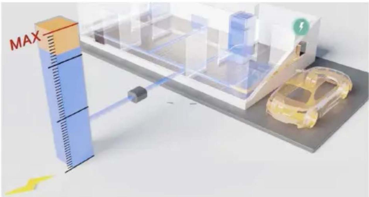
The communication to an energy meter that is connected at the household mains allows the Wallbox to regulate the charging power of the car depending on the household appliances consumption and the remaining power available.
wallbo
1. Important Notes

The charger must be installed following the respective Installation Guide, that is delivered with the charger.

Only energy meters that are delivered by Wallbox are compatible with this feature.

Only qualified people are allowed to perform the installation as it is described in this document.

Before the installation of Power Boost, the Wallbox must be powered off and its cover removed. After, the Wallbox must be properly closed, as defined in its Installation Guide.
2. Required Material and Tools
Provided by Wallbox:
• Commander, Copper or Pulsar Plus Wallbox charger
- Energy Meter
Additionally Required:
- Cable between Wallbox and Energy Meter (we recommend an STP Class 5E, 2 pair. The length depends on the customer-setup, while a maximum of 500 m can be installed).
Philips - Torx T9 (Commander or Pulsar Plus)
- Torx T20 (Copper)
• Cable pliers and stripping tools
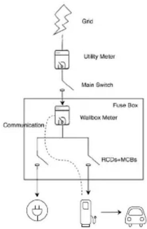
3. Location of the Energy Meter
As shown in Fig. 1, the energy meter must be located after the utility meter (labled as "Wallbox Meter") and before the split of power for the house.
Install the energy meter to the mains according to its Installation Guide.
flowchart
graph TD
    A["Grid"] --> B["Utility Meter"]
    B --> C["Main Switch"]
    C --> D["Fuse Box"]
    D --> E["Wallbox Meter"]
    E --> F["RCDs+MCBs"]
    F --> G["Power Source"]
    D --> H["Communication"]
    H --> I["Ground"]
Fig. 1: Schematic location of the Wallbox meter
CarWallboxOther house
EN
4. Cabling of the Energy Meter
After the energy meter has been installed according to its Installation Guide on the correct positioning, it must be connected to the Wallbox.
The Annex “A” describes the cabling setup to the currently supported energy meters.
5. Software Version
Please check that your charger runs on the latest software. You can check this by connecting to it with the Wallbox App and review in the settings the software version.
See the Wallbox's User Guide for more information.
wallbo
6. Definition of “Max. current per phase”
Max. current per phase: this value is the rated current of the main circuit breaker (MCB) of your electrical installation. This value determines the maximum current your installation can withstand. This value can usually be found marked on the MCB enclosure. For example, a MCB with rated current of 20 A will usually have the text “C20” or “20A” marked on it.

Warning: contact your installer in case of doubt about the rated current of the MCB installed in your property. Only values of Max. current per phase greater than 6 A are accepted for a correct performance of the Power Boost functionality.
7. Configuration
You can configure Power Boost via the Wallbox App.
Log-in to the Wallbox App, approach the charger, select the charger and wait until the synchronization has finished. Then select the "Power Boost" box inside the settings menu for configuring the parameter as described in Chapter 6.
If your charger has been already connected to the Internet, you can perform the configuration via the App remotely.
Fig. 5: Configuration via the Wallbox App
EN

wallbox
8. Status Visualization
The following icons are visualized on the chargers screen*, once the energy meter has been detected.

Energy meter detected but not configured. Follow the chapter 7 of this manual.

Power Boost is configured but not limiting the charging power.

Power Boost is limiting the charging current. The current available for charging the car is lower than the maximum power set by the user.

In queue by Power Boost. The available power is not enough for charging the EV (lower than 6 A).

Error in the communication with the energy meter.
*Doesn't apply for Copper SB nor Pulsar Plus.
EN
Annex A.1
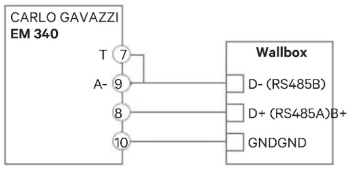
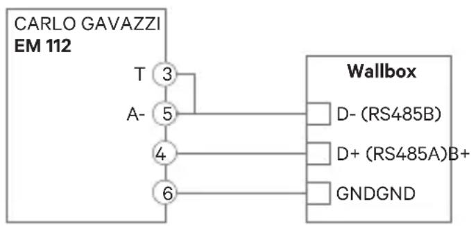
Carlo Gavazzi EM340 / EM112
The energy meter Carlo Gavazzi EM 340 is used for a 3-phase installation and the model EM112 for a 1-phase installation.
wallbo
Fig. A1.1 shows the cabling between the energy meter and the Wallbox. Please mind the required short-circuit between the pins T and A- of the energy meter.
flowchart
graph TD
    A["CARLO GAVAZZI EM 340"] --> B["T 7"]
    A --> C["A- 9"]
    A --> D["8"]
    A --> E["10"]
    B --> F["Wallbox"]
    C --> F
    D --> F
    E --> F
    F --> G["D- (RS485B)"]
    F --> H["D+ (RS485A)B+"]
    F --> I["GNDGND"]
flowchart
graph TD
    A["CARLO GAVAZZI EM 112"] --> B["T 3"]
    B --> C["A- 5"]
    C --> D["4"]
    D --> E["6"]
    E --> F["Wallbox"]
    F --> G["D- (RS485B)"]
    F --> H["D+ (RS485A)B+"]
    F --> I["GNDGND"]
Fig. A1.1: Cabling in specified energy meters
In the event that the supply scheme does not include a neutral line connection and/or the line-to-line voltage is below 260V, please connect the Carlo Gavazzi EM112 energy meter as shown in Fig. A1.2:
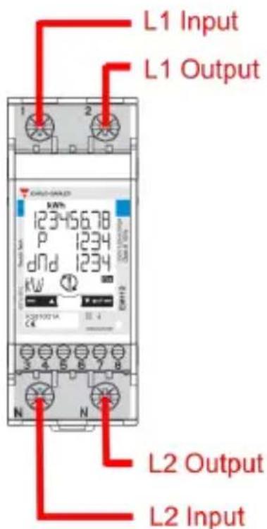
Fig. A1.2 Power lines installation on an EM112 without neutral line and/or line-to-line voltage below 260V.
EN
In the following pages Fig. A1.3, Fig. A1.4, Fig. A1.5 and Fig. A1.6 show where to connect the cabling to the Wallbox.
Depending on the model, the Wallbox may label RS485A for D+ and RS485B for D-.
wallbox
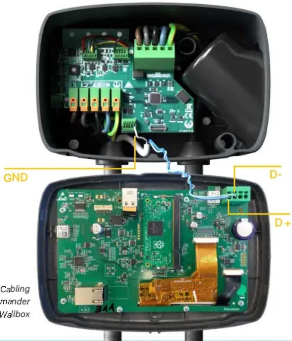
Fig. A1.3: Cabling in a Commander Wallbox

EN
Fig. A1.4: Cabling Installation in a Copper Wallbox
wallbox

Fig. A1.5 Cabling Installation in a Wallbox Pulsar Plus
EN
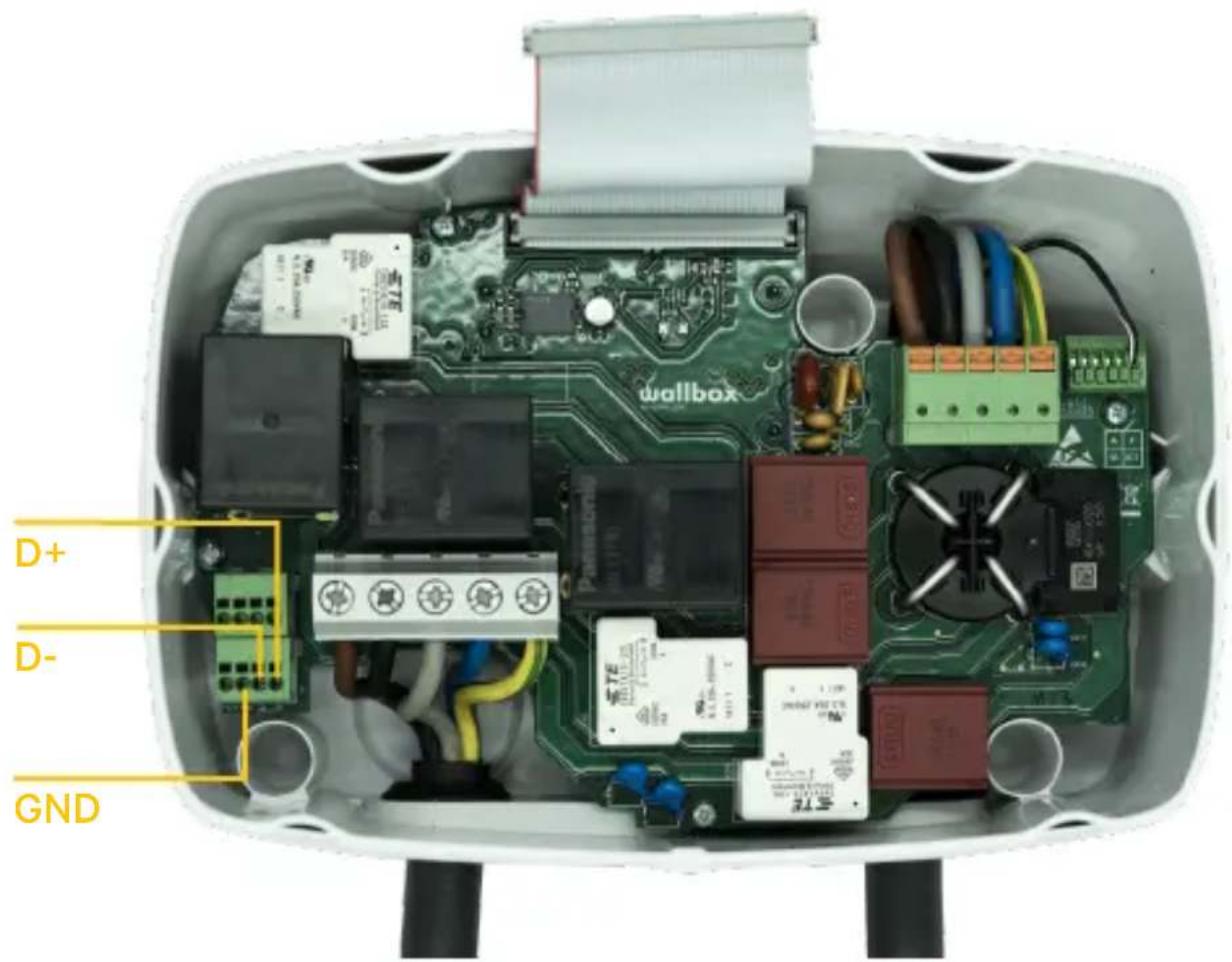
Fig. A1.6 Cabling Installation in a Wallbox Commander 2
wallbox
Annex A.2
Temco SPM1-100-AC
The energy meter Temco SPM1-100-AC is used for a 1-phase installation with up to 100 A.
The Temco power meter needs to be clipped to the mains power cable (schematic location shown in Fig. 1), with the current flowing in the direction as shown in Fig A2.1.
Only the phase-cable must be drawn through the clamp. The neutral-cable must not be drawn through.
EN
Direction of current

Fig. A2.1: Energy Meter connection diagramm
wallbox
Fig. A2.2 shows the cabling between the energy meter and the Wallbox. The numbers are referring to the Fig. A2.1. Before turning on the system it is important to check again that the connection of “GND” and “12 V” has been done correctly.

flowchart
graph TD
    A["TEMCO"] --> B["Voltage + 1"]
    A --> C["Voltage - 2"]
    A --> D["RS485 - 3"]
    A --> E["RS485 + 4"]
    A --> F["Power + 5"]
    A --> G["Power + 6"]
    H["Wallbox"] --> I["D- (RS485B)"]
    H --> J["D+ (RS485A)"]
    H --> K["GND"]
    H --> L["12 VPower +"]
Fig. A2.2: Cabling in Temco energy meter
In the following pages Fig. A2.3, Fig. A2.4, Fig. A2.5 and Fig. A2.6 show where to connect the cabling to the Wallbox.

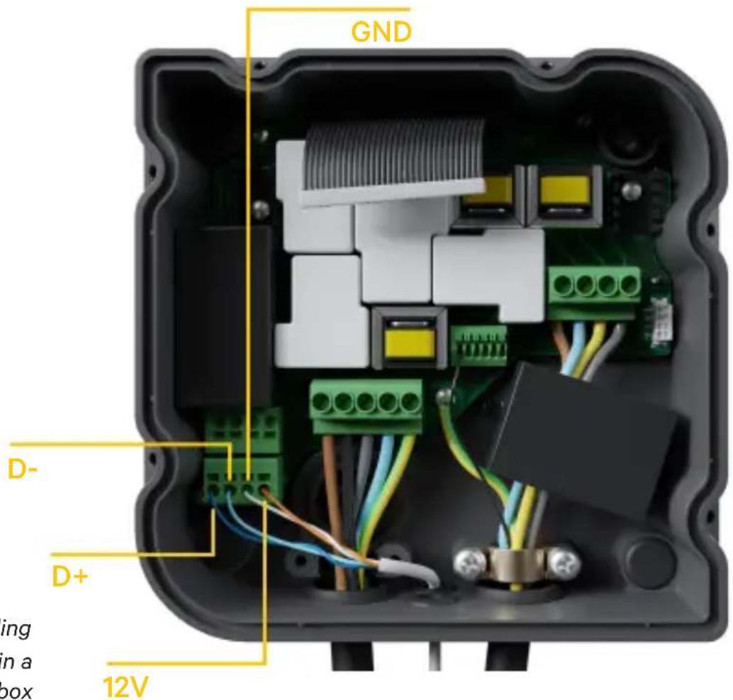
Fig. A2.4: Cabling Installation in a Copper Wallbox
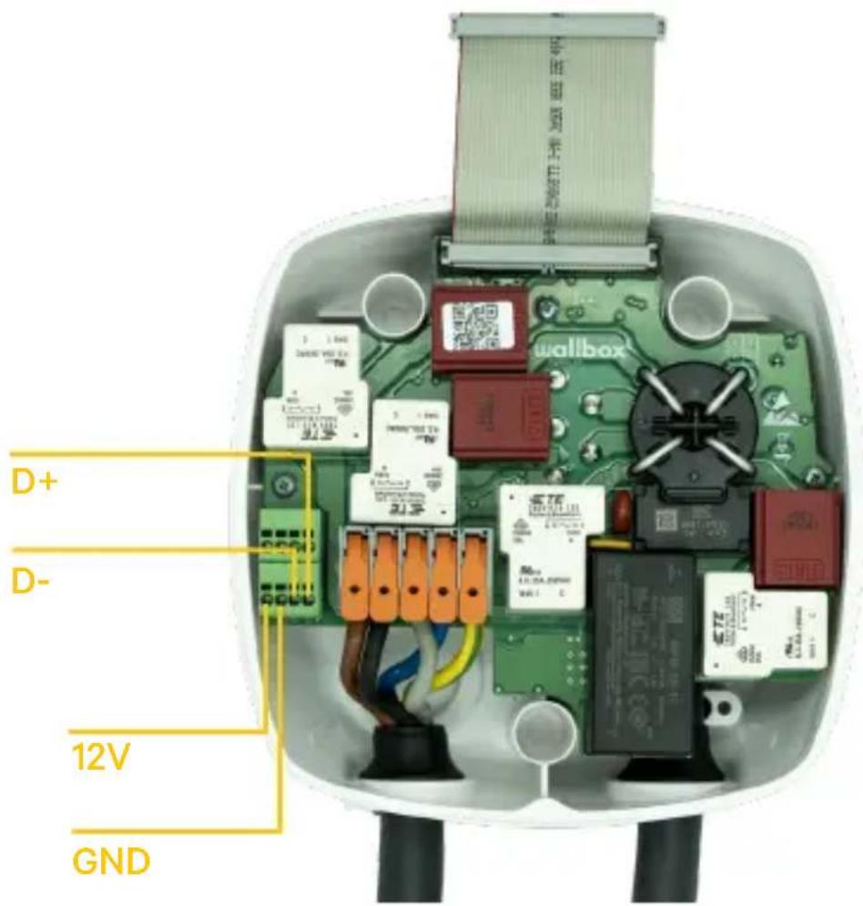
Fig. A2.5 Cabling Installation in a Wallbox Pulsar Plus
EN
wallbox

Fig. A2.6 Cabling Installation in a Wallbox Commander 2
Annex A.3
EN
wallbox
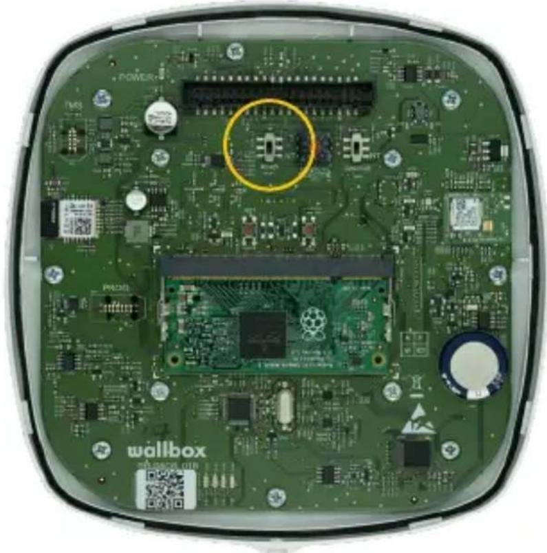
In the cover of your Pulsar Plus remember to set the RS485 switch to "T"
natural_image
Interior view of a green electronic device with visible circuit boards, components, and a highlighted circular region (no readable text or symbols)Fig. A3.1 Setting the RS485 switch to "T"
In the cover of your Commander 2 remember to set the RS485 switch to "T"
EN

natural_image
Interior view of a green electronic device with visible circuit boards, components, and a yellow circle highlighting a specific area (no readable text or symbols)Fig. A3.2 Setting the RS485 switch to "T"
wallbox
natural_image
Interior view of a green electronic device with visible circuit boards and components, no readable text or symbols.Fig. A3.1 Ajuste el interruptor RS485 a "T"
natural_image
Interior view of a green electronic device with visible circuit boards, components, and a yellow circle highlighting a specific area (no readable text or symbols)Fig. A3.2 Ajuste del interruptor RS485 a "T"
wallbox

natural_image
Interior view of a green electronic device with visible circuit boards and components, no readable text or symbols.natural_image
Interior view of a green electronic device with visible circuit boards, components, and a yellow circle highlighting a specific area (no readable text or symbols)natural_image
Interior view of a green electronic device with visible circuit boards and components, no readable text or symbols.natural_image
Interior view of a green electronic device with visible circuit boards, connectors, and components (no readable text or symbols)natural_image
Interior view of a green electronic device with visible circuit boards and components, no readable text or symbols.Fig. A3.1 Sette RS485-bryteren til «T»
natural_image
Interior view of a green electronic device with visible circuit boards, components, and a yellow circle highlighting a specific area (no readable text or symbols)Fig. A3.2 Sette RS485-bryteren til «T»
wallbox

PT
natural_image
Interior view of a green electronic device with visible circuit boards and components, no readable text or symbols.natural_image
Interior view of a green electronic device with visible circuit boards, components, and a yellow circle highlighting a specific area (no readable text or symbols)Fig. A1.3: Kab Commander Walbox
SV
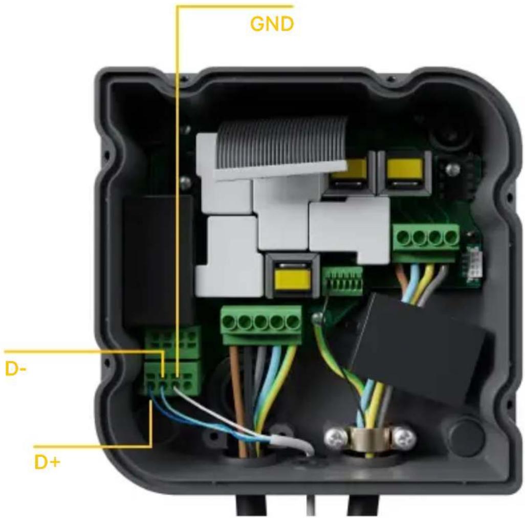
Fig. A1.4: Kabelinstallation i Copper Wallbox
wallbox

Fig. A1.5 Kabelinstallation i en Wallbox Pulsar Plus
SV

Fig. A1.6 Kabelinstallation i en Wallbox Commander 2
wallbox
Tillägg A.2
Temco SPM1-100-AC
Fig. A2.6 Kabelinstallation i Wallbox Commander 2
Bilaga A.3
SV
wallbox
natural_image
Interior view of a green electronic device with visible circuit boards, components, and a highlighted circular region (no readable text or symbols)natural_image
Interior view of a green electronic device with visible circuit boards, components, and a yellow circle highlighting a specific area (no readable text or symbols)natural_image
Interior view of a green electronic device with visible circuit boards and components, no readable text or symbols.natural_image
Interior view of a green electronic device with visible circuit boards, components, and a yellow circle highlighting a specific area (no readable text or symbols)natural_image
Interior view of a green electronic device with visible circuit boards and components, no readable text or symbols.Fig. A3.1 De RS485-schakelaar op "T" zetten
natural_image
Interior view of a green electronic device with visible circuit boards, components, and a yellow circle highlighting a specific area (no readable text or symbols)Fig. A3.2 De RS485-schakelaar op "T" zetten
wallbox


- Summary:
- Important Notes
- Required Material and Tools
- Provided by Wallbox:
- Additionally Required:
- Location of the Energy Meter
- EN
- Cabling of the Energy Meter
- Software Version
- Definition of “Max. current per phase”
- Configuration
- Status Visualization
- Annex A.1
- Carlo Gavazzi EM340 / EM112
- Annex A.2
- Temco SPM1-100-AC
- Annex A.3
- Tillägg A.2
- Bilaga A.3
Brand : Wallbox
Model : Power Boost
Category : Battery charger