
Pulsar Plus Socket - Car charger Wallbox - Free user manual and instructions
Find the device manual for free Pulsar Plus Socket Wallbox in PDF.


| Product Type | Electric Vehicle (EV) Car Charger - Socket Version |
| Brand | Wallbox |
| Model | Pulsar Plus Socket |
| Dimensions (mm) | 167 x 80 x 80 (approximate width x height x depth) |
| Weight | 1.2 kg (including cable) |
| Power Supply | 100-240 V AC, 50/60 Hz |
| Maximum Charging Power | 7.4 kW (32 A, single-phase) or 11 kW (16 A, three-phase) |
| Connector Type | Socket: Type 2 (Mennekes) / Cable: Type 2 plug (included) |
| Cable Length | Approximately 5 m (optional lengths available) |
| Protection Rating | IP54 (dust and splash water resistant) |
| Impact Resistance | IK10 (impact protection) |
| Operating Temperature | -30°C to +50°C |
| Main Functions | Smart EV charging with scheduling, power sharing, and remote monitoring via myWallbox app |
| Display | LED indicators for status and power |
| Connectivity | Wi-Fi and Bluetooth for app control |
| Certifications | CE, FCC, RCM, UL (varies by region) |
| Maintenance & Cleaning | Wipe with a soft, dry cloth; avoid water jets or solvents |
| Safety Features | Overcurrent protection, ground fault detection, overvoltage protection, emergency stop |
| Spare Parts & Repairability | Cable assembly replaceable; other repairs require authorized service |
| General Information | For indoor/outdoor use; must be installed by a qualified electrician |
Frequently Asked Questions - Pulsar Plus Socket Wallbox
User questions about Pulsar Plus Socket Wallbox
0 question about this device. Answer the ones you know or ask your own.
Ask a new question about this device
Download the instructions for your Car charger in PDF format for free! Find your manual Pulsar Plus Socket - Wallbox and take your electronic device back in hand. On this page are published all the documents necessary for the use of your device. Pulsar Plus Socket by Wallbox.
USER MANUAL Pulsar Plus Socket Wallbox
Pulsar Plus Socket – Online Installation Guide
support.wallbox.com/en/knowledge-base/pulsar-plus-socket-online-installation-guide
28 November 2023
1. Technical Specifications
You can consult the complete Datasheet here.
1.1 General Specifications
| Charging Mode (IEC 61851-1) | Mode 3 | |
| Connector Type Type 2 socket outlet (shutter) [1] | ||
| Dimensions 204.3 x 131 x 142.5 mm | ||
| Weight 2.5 kg | ||
| Operating Temperature | -30 °C to 40 °C | |
| Storage Temperature | -40 °C to 70 °C | |
| Protecting Ratings IP55, IK10 (High resistance) | ||
| Installation location Indoor and outdoor use | ||
| Mounting Method Stationary equipment is mounted on the wall. Floor mounting with appropriate Wallbox accessories. | ||
| Intended for use Equipment intended for use by ordinary persons. | ||
| Location accesses Equipment for locations with non-restricted access and restricted access. | ||
| Standards RED Directive 2014/53/EU and RoHS Directive 2011/65/EU | ||
[1]Compliant with IEC 62196-2 and NFC 15-100 for France.
1.2 Electrical Specifications
Charging Power 7,4 kW (1P) 1 11 kW (3P) 2 22 kW (3P)
Rated Voltage AC ± 10% 230 V 400 V 400 V
Rated Current 32A 32A 32A
[1]Pulsar Plus Socket can be installed in a single phase installation (see installation guide)
[2] 22kW version is limited to 11kW during installation.
Configurable Current From 6A to rated current
Rated Frequency 50 Hz / 60 Hz
Protection rating IP55 / IK10
Overvoltage Category CAT III
Residual Current Protection AC 30mA / DC 6mA
External RCD required for local regulations Type A or Type B
| Protection against electric shock | CLASS I |
| Input Cable Section | Up to 5×10 mm2 |
| Rated diversity factor (RDF) | 1 |
| Rated insulation voltage | 1430 Vrms |
| Rated impulse withstand voltage | 2500 V |
2. Safety Warnings
A

B

C

D

E

F

• A. Flying debris, risk of eye injury
• B. Risk of electric shock. Disconnect and wait 10 mins.
C. Caution
• D. Sharp element, risk of dangerous cuts
• E. Ground earth connection required
• F. Special waste treatment
3. Safety Instructions
You can consult the Safety Instructions here.
4. Tools and Mounting Parts
Required tools

- Hammer
- Step drill bit 8mm
- Pencil
- Sprit Level
- Measuring Tape

- Cutting Pliers
- HEX tube key ∅6
• Security Torx T20 - Utility knife
- Mobile Phone
Included Parts

x2
∅8×40mm
x2 HEX
∅6×40mm
x7 T20
∅4×10mm
x2 T20 security
∅4×10mm
5. Installing the Wallplate

natural_image
Cross-sectional diagram of a device casing with internal components and directional arrows (no text or symbols)- Remove the tape from the wall plate to detach it from the charger.
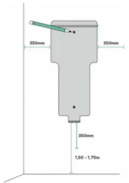
- Place the wall plate straight. Use a pencil, a measuring tape and a sprit level to mark the position of the screws.

natural_image
Three circular icons showing a pencil, a bell icon, and a balance scale (no text or symbols)
DISCLAIMER
If your power supply wiring comes from the wall, ensure that the wall plate is positioned so that the body hole aligns with the power supply wiring.

- Drill three holes with the appropriate sized bit. Place the wall plate in alignment with the holes. If you mount your charger on a solid wall, use the wall anchors provided.


- Firmly mount the wall plate using the provided wall screws. Do not over-tighten the screws. If the power supply wiring comes from the wall, place the wires through the hole before fixing the wall plate.

6. Preparing the Charger
Make sure to power off all the connections before going through these steps.

natural_image
Diagram of a wallbox device with directional arrows indicating flow or movement (no text or symbols beyond 'wallbox')- Unclip the style cover by pressing the socket lid with your fingers carefully.

natural_image
3D rendering of a wallbox device with visible ports and wiring (no text or symbols)- Remove the two corner screws and carefully lift the cover.
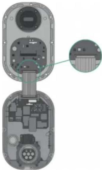
natural_image
Exploded view diagram of a device showing internal components and a close-up inset (no text or symbols)- Carefully detach the ribbon cable from the cover by pressing the lateral latches. Set the cover aside.
IMPORTANT: Make sure to power off all the connections.
7. Lower Connection
IMPORTANT
Follow these instructions only if you intend to install the product by using the lower hole. For the rear connection, go to part "7. Rear Connection".

natural_image
Technical illustration of an open device with internal components and a separate view showing a mechanical part (no text or symbols present)- Lift your charger and hang it from the top of the wall plate.

natural_image
Cross-sectional diagram of a mechanical device showing internal components and housing (no text or symbols)- Secure the charger to the wall plate using the security screws.


T20 4x 10mm Security Torx Screws

natural_image
Cross-sectional diagram of a mechanical device showing internal components and assembly (no text or symbols)- Make an incision on the lower grommet and insert the power supply cable. Make sure the grommet seals entirely the power cable supply insertion.

8. Rear Connection

natural_image
Diagram of a mechanical component with a green arrow indicating direction, no text or symbols present- Make an incision on the rear grommet and insert the power supply cable. Make sure the grommet seals entirely the power cable supply insertion.

natural_image
Technical illustration of a mechanical device showing internal components and a separate view with a curved arrow indicating rotation (no text or symbols present)- Lift your charger and hang it from the top of the wall plate.

natural_image
Cross-sectional diagram of an electronic device showing internal components and wiring (no text or labels)- Secure the charger to the wall plate using the security screws.


natural_image
Cross-sectional diagram of a mechanical device showing internal components and housing (no text or labels)- Proceed to the next section to connect the power supply cable.
9. Electrical Wiring
Please refer to the wiring diagram provided below following your electrical setup.
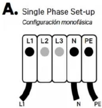

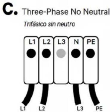


F. Ensure that the maximum voltage is less than 264 V between L & N inputs.
10.1. Maximum Current Selection

natural_image
Interior view of a mobile phone module showing internal components and a close-up of the main panel (no text or symbols visible)- Locate the current selector inside the charger.
| POSITION | 0 | 1 | 2 | 3 | 4 | 5 | 6 | 7 | 8 | 9 |
| CURRENT (A) | R | 6 | 10 | 13 | 16 | 20 | 25 | 32 | R | R |

Only for Germany: According to VDE-AR-N 4100.2019-04, if the installation is single phase, the maximum current needs to be set to a value equal or lower than 20A.
- To set the maximum charging current of the charger, position the current selector to the appropriate setting following the tab. Make sure the selector does not point to 0, 8 and 9.
10.3. Closing the Charger
natural_image
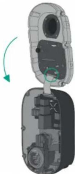
3D diagram of a device showing internal components and a green arrow indicating rotation (no text or symbols)- Carefully reattach the communication cable to the charger cover and close it.

natural_image
3D diagram of a wallbox device with labeled components and wiring (no text or symbols beyond branding)- Insert seven corner screws to secure the charger cover. Do not over-tighten.


natural_image
Diagram of a wallbox device showing front and side views (no text or symbols on the device itself)- Clip back the cover frame on the charger and fix it with the other security screw. Do not over-tighten.


T20 4x 10mm Security Torx Screws
Torque:
(1.5N·m)
10.4. Making the charger smart
- Download the myWallbox app and create an account for the client.
- Follow this guide to add the charger to your newly created account.
- Make sure your charger is updated to its latest software version.
- You can now use all the charger smart features such as scheduled charging sessions, managing the charger through the myWallbox portal and adjusting your charger settings.

- Pulsar Plus Socket – Online Installation Guide
- Technical Specifications
- General Specifications
- Electrical Specifications
- Safety Warnings
- Safety Instructions
- Tools and Mounting Parts
- Required tools
- Included Parts
- Installing the Wallplate
- DISCLAIMER
- Preparing the Charger
- Lower Connection
- IMPORTANT
- Rear Connection
- Electrical Wiring
- Maximum Current Selection
- Closing the Charger
- Making the charger smart
Brand : Wallbox
Model : Pulsar Plus Socket
Category : Car charger