380736 - Welding machine SILVERLINE - Free user manual and instructions
Find the device manual for free 380736 SILVERLINE in PDF.
| Product type | MIG-MAG welding machine |
| Brand | Silverline |
| Model | 380736 |
| Dimensions (H x W x D) | 680 x 300 x 500 mm |
| Weight | 24.85 kg |
| Power supply | 230 V ~, 50 Hz |
| Input current | 29.4 A (peak), 12 A (average) |
| Output current range | 30 - 135 A (steps: 30, 43, 52, 78, 105, 135) |
| No-load voltage | 37 V |
| Output voltage | 20.75 V (135 A), 16.15 V (43 A), 15.5 V (30 A) |
| Duty cycle | 10% at 135 A, 60% at 43 A, 100% at 30 A |
| Wire diameter | 0.6 - 0.8 mm |
| Weld thickness (steel) | 1.2 - 6.5 mm |
| Protection class | H |
| Ingress protection rating | IP21S |
| Torch cable length | 2 m |
| Ground cable length | 1.5 m |
| Power cable length | 2 m |
| Gas hose | 4 mm diameter |
| Included accessories | Welding helmet, hammer-brush, 0.6 mm tip |
| Main functions | MIG/MAG welding with or without gas (flux-cored wire), voltage and wire feed speed adjustment, thermal protection |
| Maintenance and cleaning | Regular cleaning, tip replacement (consumables) |
| Safety | Thermal protection, automatic shutdown on overheating, mandatory grounding |
| Spare parts and repairability | Parts available at toolsparesonline.com, Silverline after-sales service |
| Warranty | 3 years (subject to online registration within 30 days) |
Frequently Asked Questions - 380736 SILVERLINE
User questions about 380736 SILVERLINE
0 question about this device. Answer the ones you know or ask your own.
Ask a new question about this device
Download the instructions for your Welding machine in PDF format for free! Find your manual 380736 - SILVERLINE and take your electronic device back in hand. On this page are published all the documents necessary for the use of your device. 380736 by SILVERLINE.
USER MANUAL 380736 SILVERLINE
text_image
Collection of safety and hazard symbols and technical diagrams, including protective gear, warning signs, and electrical hazard symbols.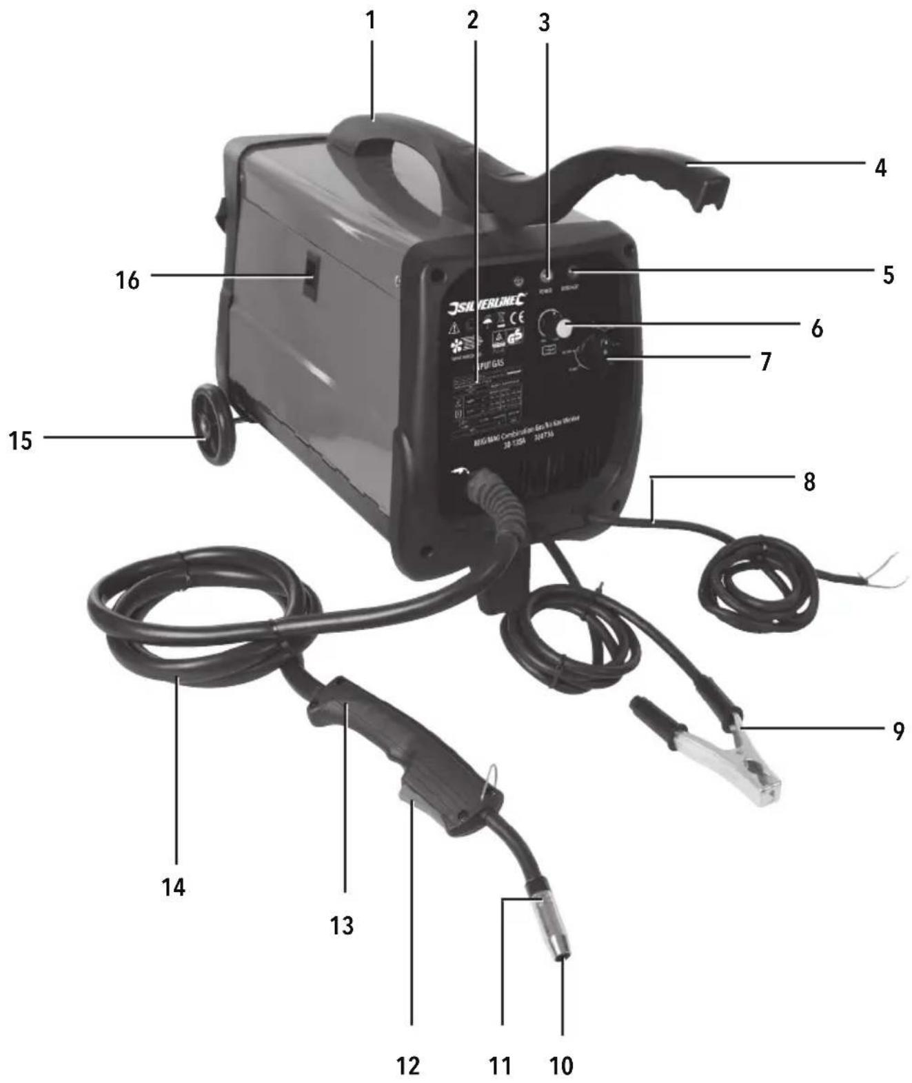
text_image
1 2 3 4 5 6 7 8 9 10 11 12 13 14 15 16 JISVERLINE CANDIATION Gas-Elec Bracket JDS 1228 202736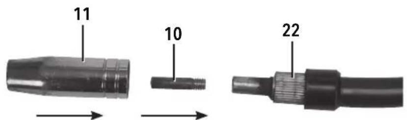
text_image
11 10 22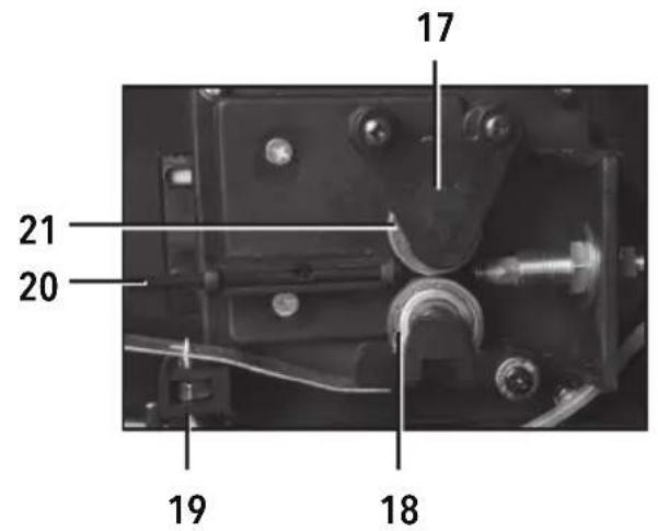
text_image
17 21 20 19 18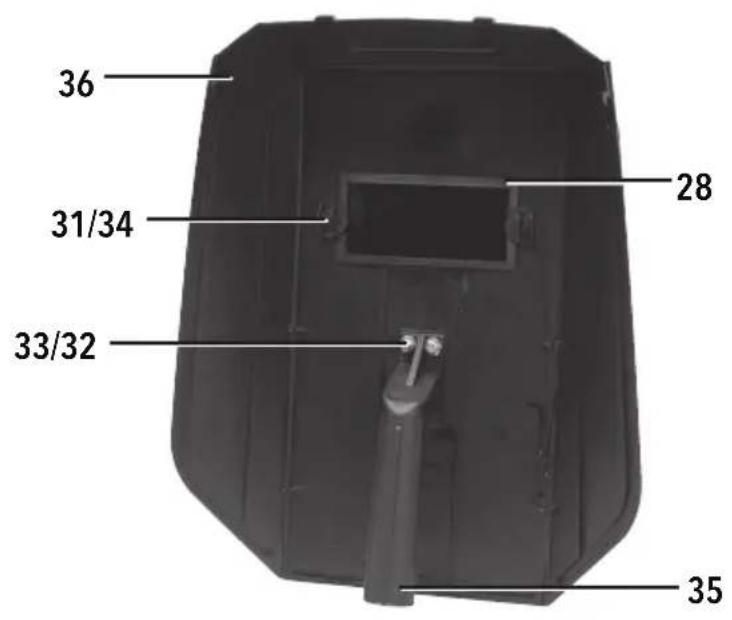
text_image
36 31/34 33/32 28 35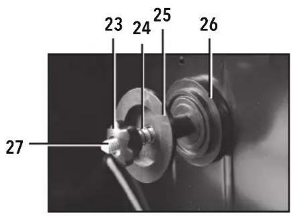
text_image
23 24 25 26 27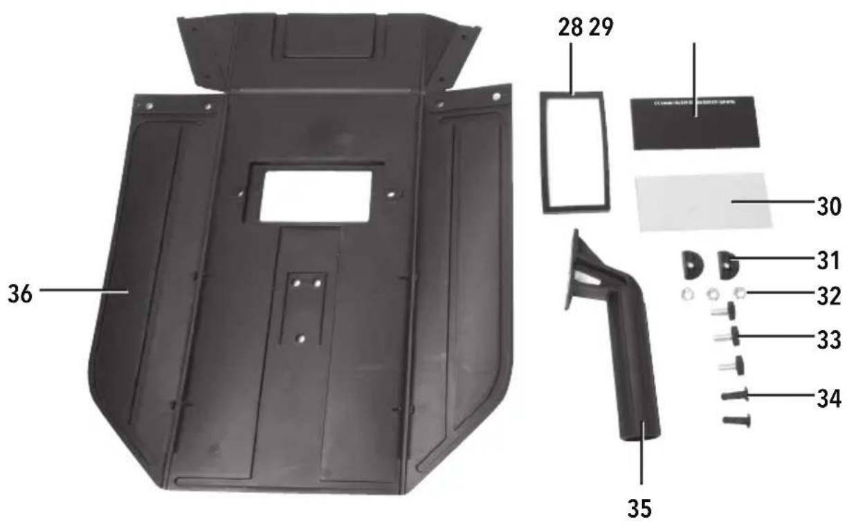
text_image
36 28 29 30 31 32 33 34 35A
natural_image
Close-up of a metallic mechanical component with a central button (no visible text or symbols)B
natural_image
Close-up of a mechanical clamp or bracket component with three screws, no visible text or symbolsC
natural_image
Close-up of a black curved object with a metallic clip attached, showing no visible text or symbols.D
natural_image
Close-up of a mechanical pulley or wheel with five spokes (no text or symbols visible)E
natural_image
Close-up of a white cylindrical object attached to a black plastic car (no visible text or symbols)F
natural_image
Close-up of a metallic mechanical valve component with black and white top (no visible text or symbols)G
text_image
Safety warning sign showing no hazard and a flame symbol on a device panelH
natural_image
Close-up of a black cable with a metallic connector (no text or symbols visible)|
natural_image
Close-up of mechanical components with bolts and fittings (no visible text or symbols)J
natural_image
Close-up of mechanical components with no visible text or symbolsEnglish ......06
Français ......14
Deutsch......22
Español......30
Italiano ....38
Nederlands ......46
Polski ....54
Introduction
Thank you for purchasing this Silverline tool. This manual contains information necessary for safe and effective operation of this product. This product has unique features and, even if you are familiar with similar products, it is necessary to read this manual carefully to ensure you fully understand the instructions. Ensure all users of the tool read and fully understand this manual.
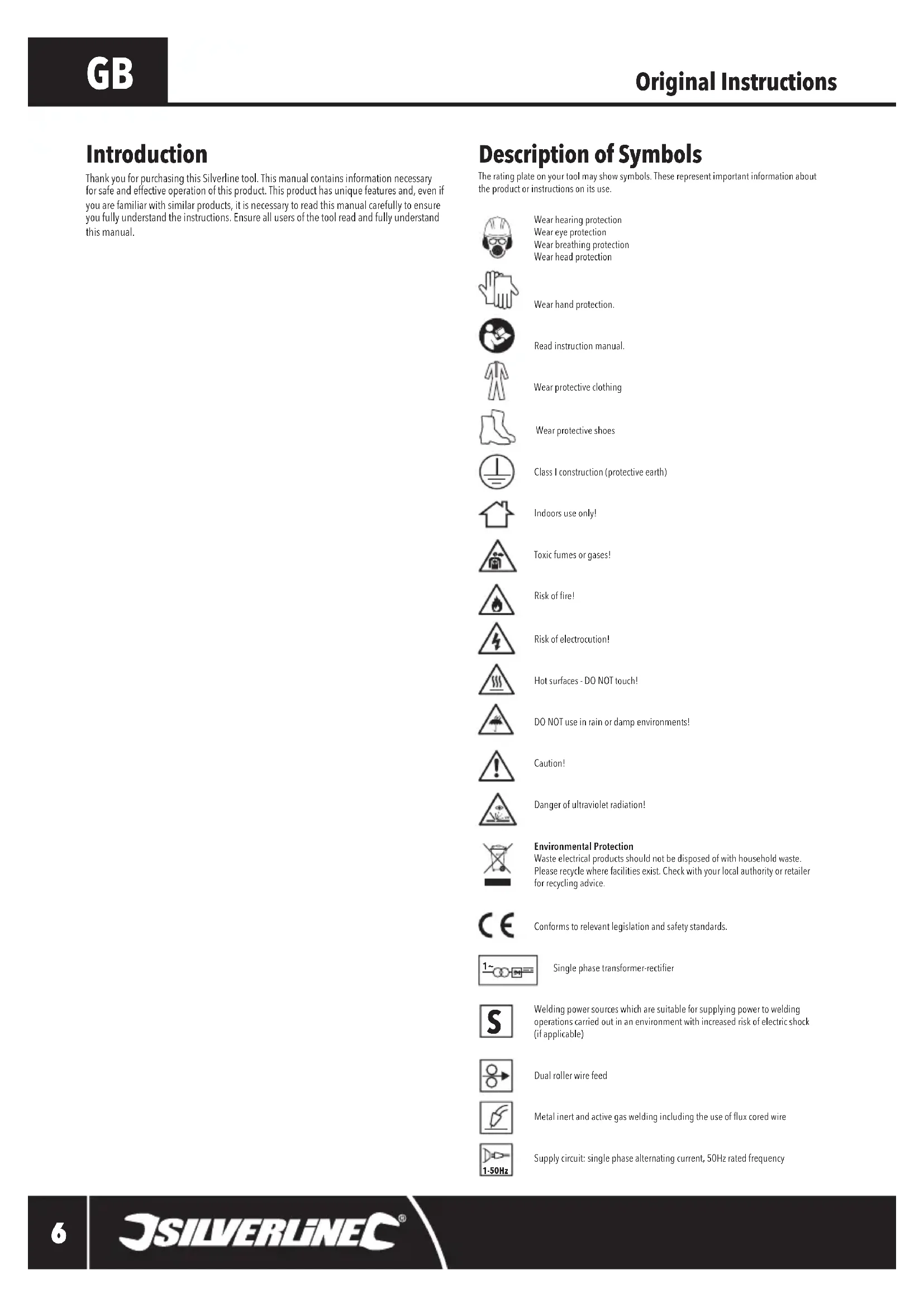
Description of Symbols
The rating plate on your tool may show symbols. These represent important information about the product or instructions on its use.

Wear hearing protection
Wear eye protection
Wear breathing protection
Wear head protection

Wear hand protection.

Read instruction manual.

Wear protective clothing

Wear protective shoes

Class I construction (protective earth)

Indoors use only!

Toxic fumes or gases!

Risk of fire!

Risk of electrocution!

Hot surfaces - DO NOT touch!

DO NOT use in rain or damp environments!

Caution!

Danger of ultraviolet radiation!

Environmental Protection
Waste electrical products should not be disposed of with household waste. Please recycle where facilities exist. Check with your local authority or retailer for recycling advice.

Conforms to relevant legislation and safety standards.
Single phase transformer-rectifier

Welding power sources which are suitable for supplying power to welding operations carried out in an environment with increased risk of electric shock (if applicable)

Dual roller wire feed

Metal inert and active gas welding including the use of flux cored wire

Supply circuit: single phase alternating current, 50Hz rated frequency
Technical Abbreviations Key
| V Volts | |
| ~, a.c. Alternating current | |
| A, mA Ampere, milli-Amp | |
| ∅ Diameter | |
| Hz Hertz | |
| -, d.c. Direct current | |
| W, kW Watt, kilowatt |
Specification
Input voltage: 230V\~50Hz
Input current: 29.4A(peak), 12A(average)
Efficiency: 80%
Output current range: 30-135A(30, 43, 52, 78, 105, 135)
Rated duty cycle:....10%@135A, 60%@43A, 100%@30A
No load output voltage: 37V
Output voltage: 20.75V(135A), 16.15V(43A), 15.5V(30A)
Insulation class: H
Ingress protection: IP21S
Wire: 0.6-0.8mm
Welding thickness range (steel): 1.2 - 6.5mm
Mains circuit breaker fuse: 32A or 30A
Protection class:
Torch cable length:....2m
Earth cable length: 1.5m
Gas tube: 04mm
Power cable length: 2m
Dimensions (H x L x W): 680 x 300 x 500mm
Weight: 24.85kg
As part of our ongoing product development, specifications of Silverline products may alter without notice.
General Safety
WARNING: Read this manual before operating, adjusting and servicing this welder.
WARNING SIGHT RISK: Arc glare can permanently damage your eyesight. Always use a suitable welding mask, face shield or helmet. Always check condition of eye protection before use.
⚠ WARNING: FIRE RISK: All flammable materials must be removed from the welding area.
⚠ WARNING: WELDING FUMES: Toxic gases are given off during welding. Always use in a well-ventilated area.
WARNING: BURN RISK: Wear welding gloves at all times when welding. They will reduce the risk of burn injuries and ultra-violet radiation. In addition, wear a leather apron to protect from spatter and a cap when welding overhead.
WARNING: This appliance is not intended for use by persons (including children) with reduced, physical or mental capabilities or lack of experience or knowledge unless they have been given supervision or instruction concerning use of the appliance by a person responsible for their safety. Children must be supervised to ensure that they do not play with the appliance.
Keep work area clear - Cluttered areas and benches invite injuries
- Consider work area environment
- Do not expose welder to rain
- Do not use welder in damp or wet locations
Keep work area well lit
- Keep other persons away. Do not let persons, especially children, not involved in the work touch the tool or the extension cord and keep them away from the work area
⚠ WARNING: Not using protective equipment or appropriate clothing can cause personal injury or increase the severity of an injury.
- Do not abuse the power cable. Never pull the power cable to disconnect it from the socket. Keep the power cable away from heat, oil and sharp edges. Damaged or entangled power cables increase the risk of electric shock
- Do not overreach. Keep proper footing and balance at all times
- Maintain tools with care
- Inspect tool power cables periodically and have them repaired by an authorised service facility if damaged
- Inspect extension cables periodically and replace if damaged
- Disconnect - Disconnect welders from the power supply when not in use, before servicing and when changing accessories
⚠ WARNING: The use of accessories or attachments not recommended by the manufacturer may result in a risk of injury to persons.
- Stay alert
- Watch what you are doing, use common sense and do not operate the tool when you are tired
- Do not use a welder while you are under the influence of drugs, alcohol or medication
⚠ WARNING: A moment of inattention while operating power tools may result in serious personal injury.
- Check damaged parts
⚠ WARNING: Do not use the welder if the on/off switch does not switch the tool on and off. The switch must be repaired before the welder is used.
- Have your tool repaired by a qualified person. This welder complies with the relevant safety rules. Repairs should only be carried out by qualified persons, otherwise this may result in considerable danger to the user
WARNING: When servicing use only identical replacement parts.
⚠ WARNING: If the power cable is damaged it must be replaced by the manufacturer or an authorised service centre.
⚠ WARNING: Power tool mains plugs must match the mains socket. Never modify the plug in any way. Do not use any adaptor plugs with earthed (grounded) power tools. Unmodified plugs and matching sockets will reduce risk of electric shock.
Welding Safety
⚠ WARNING: DO NOT strike an arc close to the gas bottle.
WARNING: DO NOT lift the welder with a gas bottle attached.
WARNING: DO NOT use a welder for pipe thawing.
WARNING: AVOID unintentional arcing of the welder. Switch off the welder when not in use.
IMPORTANT: Use of welding machines creates powerful magnetic fields. This may disturb the operation of sensitive electronic equipment. Pacemaker wearers should consult a doctor before using a welding machine.
IMPORTANT: Do not overload a mains circuit. Check that your mains wiring is capable of delivering the required current safely. If unsure consult a professional electrician before use.
- Welding produces toxic fumes and can reduce oxygen levels in the work area. Always work in a well-ventilated area. Avoid inhaling welding fumes, use a suitable respirator where appropriate
- Some metal parts may have zinc, lead, cadmium or other coatings. Attempting to weld through these coatings can produce highly toxic fumes. Always remove all coatings before welding
- If you experience irritation to the lungs, throat or eyes whilst welding, STOP IMMEDIATELY and seek fresh air
- Welding produces extremely high levels of UV light. To prevent eye damage, ALWAYS use an approved welding face mask. Under no circumstances look directly at the arc
- The light produced when arc welding can be attractive to look at, especially to children. Always prevent other people from viewing the arc welding light with unprotected eyes
- If there is a possibility of other people approaching the work area, erect suitable screening to protect them from the light / glare
- Always replace the welder face mask glass as soon as it shows any signs of wear or damage
- To prevent skin damage, ALWAYS wear a suitable fire-proof long sleeved jacket, heat proof gloves, and cap. Keep covered up
- Always remove any flammable materials (e.g. cigarette lighter, matches) from your clothing before welding
• Always keep a fire extinguisher nearby when welding - Sparks generated while welding can ignite flammable materials easily in the welding area. So it is important to remove flammable materials before commencing welding
- Only weld when the work area and all workpieces are dry
- Do not weld sealed containers (e.g. fuel tanks, air tanks, oil drums). The heat generated from welding can cause sealed containers to burst without warning
- Be aware of transferred heat. Metal parts can conduct heat away from the work area and cause ignition of flammable materials
- Be aware that welded parts will remain hot for some time after joining. Allow to cool completely before handling, or leaving unattended
- Never weld where flammable gases, liquids or dust are present
- Ensure that there is always a responsible person nearby to alert you to any fire, or to call help in an emergency
- Workpieces with burred edges can damage the torch cable. Always ensure the torch cable will not be damaged as it moves over a surface
Wire feed
- Caution: The tip of welding wire can be very sharp, and is fed with adequate force to puncture skin
- Keep the welding machine switched off until you are ready to begin welding. Never point the torch towards people or animals
Product Familiarisation
| 1 Carrying Handle |
| 2 Rating Label |
| 3 Power Light |
| 4 Extended Handle |
| 5 Over-Heat Indicator |
| 6 Wire Feed Speed Dial |
| 7 Voltage/Current Selector |
| 8 Mains Cable |
| 9 Earth Clamp |
| 10 Tip |
| 11 Shroud |
| 12 Trigger |
| 13 Torch Handle |
| 14 Torch Cable |
| 15 Wheel |
| 16 Panel Release |
| 17 Rollers Cover |
| 18 Power Roller |
| 19 Roller Tension Adjuster |
| 20 Wire Input |
| 21 Upper Roller |
| 22 Tip Holder |
| 23 Spool Nut |
| 24 Tension Spring |
| 25 Spool Retainer |
| 26 Wire Spool |
| 27 Spool Thread |
| 28 Filter Frame |
| 29 Welding Filter |
| 30 Spatter Shield |
| 31 Frame Clips (x 2) |
| 32 Handle Nuts (x 3) |
| 33 Handle Bolts (x 3) |
| 34 Frame Screws (x 2) |
| 35 Handle |
| 36 Welding Mask |
Accessories (not shown)
- Hammer Brush
- 0.6mm tip
Intended Use
Gas Metal Arc Welding (GMAW) welder for light to medium-duty Metal Inert Gas (MIG) & Metal Active Gas (MAG) shielded welding applications, for use with various types of steel. Can use suitable flux-cored welding wire spools or standard non-flux wire spools when connected to a gas bottle or gas supply. This product is not designed for commercial, trade or industrial applications.
Unpacking Your Tool
- Carefully unpack and inspect your tool. Fully familiarise yourself with all its features and functions
- Ensure that all parts of the tool are present and in good condition. If any parts are missing or damaged, have such parts replaced before attempting to use this tool
Before Use
⚠ WARNING: Always unplug the welding machine from the mains supply and allow to cool fully before attempting to fit or replace any part.
IMPORTANT: This tool is earthed and must only be connected to mains with an earth connection. Do not attempt to use it without an earth connection.
IMPORTANT: Connecting to mains
- This welder is not supplied with a mains electrical plug because at full capacity it will draw far too much current for a normal domestic mains plug and socket.
- A high current mains socket or terminal must be installed by a qualified and accredited professional electrician. A 32A socket and plug conforming to IEC 60309 is recommended
- A non-socketed mains connection also requires welder connection by a qualified and accredited professional electrician. However, a socketed connection is safer and more strongly recommended so the welder can be safely isolated when necessary. If directly wired to mains, a double pole, double throw isolator switch must be fitted
- The welder must be connected to a consumer unit with a built-in RCD, using a circuit protected by an RCD
- Please refer to the Specification for details of the maximum current required by this welder
- If in any doubt, do not attempt to connect or use this welder until a professional electrician has been consulted
WARNING: If connected to a standard domestic mains socket use with CAUTION. For European 16A sockets use up to the 78A setting only and for UK 13A mains sockets use up to 52A setting only. Use at higher settings can damage your mains wiring and insulation and be a fire risk. It is recommended only to use this welder on a dedicated 32A mains connection. Use on a circuit of less than 32A at high peaks of current will repeatedly trip mains circuit breakers and fuses.
Assembling the welder
- Align the holes in the Extended Handle (4) with the holes on the top of the Carrying Handle (1) and securely tighten the screws (using the screws provided) (Image A) and then fit the plastic cover
- Align the front leg with the holes under the front of the welder if not pre-fitted and secure with screws (Image B)
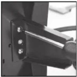
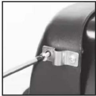
- Fit the 2 metal brackets underneath the rear of the welder (Image C)
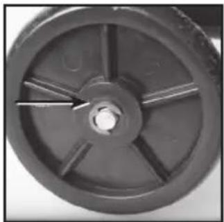
- Slide the bar through the 2 brackets and fit a Wheel (15) to each end securing each Wheel with the circlip (arrowed in Image D). It is easier if one Wheel is secured to the bar before fitting through the brackets
Assembling the mask
- Use the mask clips to assemble the flat-packed Welding Mask (36) into its normal shape
- Fit the Handle (35) using the Handle Nuts (32) and Handle Bolts (33). The Handle must be inside the Welding Mask body to protect the operator's hand from spatter
- Ensure the Spatter Shield (30) protects the Welding Filter (29) from weld spatter. If the Welding Filter is fitted as the external layer, it may get damaged by spatter and allow dangerous ultraviolet light to reach the operator's eyes
- Fit the glass assembly into the Welding Mask using the Frame Screws (34) and Frame Clips (31).
Installing wire
- While turning clockwise pull off the Shroud (11) then unscrew the exposed Tip (10) anticlockwise with a spanner. Then unwind the Torch Cable (14) so it is as straight as possible and in line with the wire feed mechanism
- Press up on the Panel Release (16) and lower the side flap of the case
- Turn the Spool Nut (23) anti-clockwise and remove it carefully with the Tension Spring (24) and Spool Retainer (25)
- Place a Wire Spool (26) over the Spool Thread (27), positioning so that the wire will feed off the Wire Spool at the correct height for the Wire Input (20)
- Refit the Spool Retainer, Tension Spring and Spool Nut and tighten so the spool will not unravel on its own
-
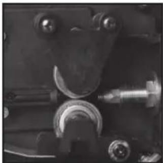
If you need to change or turn the Upper Roller (21), so the correct size groove for the wire is in line with the inner liner of the Torch Cable (14), remove the 2 screws of the Rollers Cover (17) and use a spanner to remove the roller securing component (Image I), then turn or replace the roller with the correct size
-
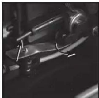
Lift the metal tension bar clear of the point of the Roller Tension Adjuster (19) and move to the side so there is a sufficient gap between the Upper Roller and Lower Roller (18) for the wire to feed through (Image J)
- Carefully release the end of the wire from the Wire Spool (26) and take care not to let the wire unravel. Ensure that the wire is straight for 75 - 100mm and is cut off cleanly with a smooth tip that will not damage the Torch Cable liner. There must be no burrs on the wire
- Slowly feed the wire into the end of the Wire Input (20) across the rollers and into the Torch Cable liner. Push a little way into the liner carefully until some resistance is felt
- Swing the metal tension bar into position, ensuring that the wire is centred in the grooves of the upper and lower rollers. Tension can be adjusted with the Roller Tension Adjuster (19) if necessary
IMPORTANT: The Spool Nut should only be adjusted with enough tension that will cause the spool only to turn when the wire is feeding correctly into the Torch Cable liner and the Roller Tension Adjuster should be adjusted so the wire will slip on the rollers if there is resistance in the Torch Cable liner. - Cover the wire feeding mechanism with the flap and secure with the Panel Release (16)
12.Isolate the Earth Clamp (9) by placing on a non-metallic, non-conductive surface - Set the Wire Feed Speed Dial (6) to the slowest setting
- Connect the welder to the mains power supply, switch on, and hold the Torch Handle (13)
- Move the torch away from the machine, so that the Torch Cable is straight and in line with the wire feed mechanism so the wire will have minimal resistance
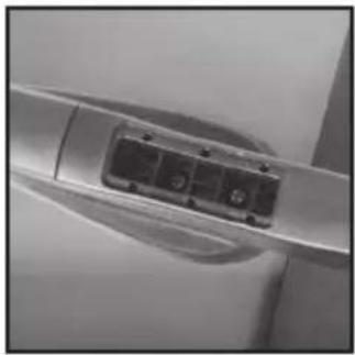
- Ensure that the torch is not touching anything, and squeeze the Trigger (12). The wire feed mechanism should drive the wire through to the torch (Image H)
- If the wire is not driven through, disconnect from the mains power supply and adjust the Roller Tension Adjuster (19)
- When the wire is propelled out of the end of the torch, switch off and disconnect from the mains power supply
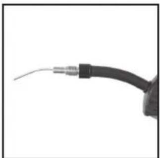
- Refit the Tip and the Shroud, and trim the wire so that approximately 3mm projects from the Tip
IMPORTANT: Use clean compressed air to clean the Torch Cable liner if the wire will not feed through.
Removing wire reel and end of wire
- Open the side flap of the welder using the Panel Release (16) and check if the old Wire Spool (26) is empty
- If not empty cut the wire at the Wire Spool and loop back and secure on the Wire Spool if intending to continue using at a later date
- Lift the metal tension bar clear of the point of the Roller Tension Adjuster (19) and move to the side (Image J)
- Use a pair of pliers to draw the last of the old Wire Spool (26) out through the Tip (10) of the torch
- Then proceed as per instructions for 'Installing wire' above
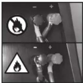
Configuring for flux wire operation
- For 'no gas' operation using flux wire spools the polarity of the Earth Clamp (9) and the torch must be correct. Open the side flap of the case using the Panel Release (16)
- On the right side the cable connections can be seen (Image G). Check that the black cable goes to the red left positive connection and the red cable goes to the right side black negative connection. Reverse if necessary
Configuring for gas operation
- For 'gas' operation using non flux plain wire spools
- The polarity of the Earth Clamp (9) and the torch must be correct. Open the side flap of the case using the Panel Release (16)
- On the right side the cable connections can be seen (Image G). Check that the black cable goes to right side black negative connection and the red cable goes to the red left positive connection. Reverse if necessary
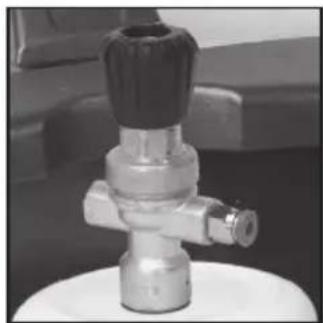
- A regulator is required to connect to the ∅4mm gas tube that will adapt to your chosen gas bottle or cylinder
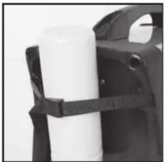
- To mount a gas bottle to the rear of the welder, position the welder in the correct position before adding the bottle. Secure the bottle securely with the strap provided (Image E) and attach the regulator (not supplied) following the instructions provided. A typical regulator is shown in Image F. Read all safety warnings provided with or attached to the gas bottle or cylinder
- Do a final check for all fittings to ensure they are all satisfactory and safe
IMPORTANT: DO NOT OVER-TIGHTEN THE REGULATOR ON TO THE GAS CYLINDER
Note: Any safety information provided with the regulator or gas bottle supersedes this information.
When fitting the regulator onto the gas cylinder, check the tap valve is fully turned off and inside the connection to the gas bottle has satisfactory seals. When fitting the regulator, it is normal to hear a hiss of gas escape through the pressure relief hole near the bottom of the regulator. This is to be expected and does not mean that there is a problem. The leakage will stop as the regulator makes contact with the seal.
Do not over-tighten the regulator onto the gas cylinder as there is a risk unscrewing the regulator will cause the cylinder to be thrust violently from your hand. When removing regulators from gas cylinders, always do so at arm's length. Ensure that the cylinder's gas valve is not disturbed. If you see the cylinder's gas valve start to unscrew it will be caused by an over-tightened regulator. In these circumstances refit and retighten the regulator immediately and discharge all gas into the atmosphere by opening the regulator valve before re-attempting to remove the regulator.
Operation
IMPORTANT
- Always wear appropriate personal protective equipment for the job that you are about to do. Use of this machine requires a welding mask, gloves, heat-resistant clothing and, if appropriate, a respirator
• Always ensure that you have an appropriate fire extinguisher near to the work area - Always inspect your machine for damage or wear. Pay particular attention to leads and cables. If any damage is found, DO NOT USE
- Check that all casings or covers are properly closed and secured
- Position the welder in such a way that it will not move or tip in use. Ensure that there is at least 500mm of clear space around the welder to allow proper ventilation
| 15.5V 16.15V 16.6V | 17.9V 19.25V 20.75V | |||||
| Current 1_c A 30A | 43A 52A 78A | 105A 135A | ||||
| Duty Cycle X % (minutes per 10 minutes) | 100% (10min) | 60% (6min) | 50% (5min) | 20% (2min) | 15% (1.5min) | 10% (1min) |
| Metal Thickness * Approximate guide | 1.2mm 2mm | 3.2mm 4mm | 5.2mm | 6.5mm | ||
Setting the machine
• To achieve a good quality weld, the Voltage/Current Selector (7) must be set correctly. See chart
- Use Wire Feed Speed Dial (6) to make minor adjustments to wire speed to provide a steady arc. The correct setting will depend on distance, current, torch speed, and other factors. Experiment with wire speeds until you find an optimum setting
Duty cycle
- This machine is not designed for continuous welding. Excessive continuous welding would cause overheating and damage to internal components
- The duty cycle defines the number of minutes, in every ten minutes, that the machine can weld
- For a duty cycle of 10%, the machine may be used for 1 minute, and then must be allowed 9 minutes to cool. The 60% duty cycle allows 6 minutes in every 10 minutes. See chart
- If the duty cycle is exceeded, the machine will automatically cut-out
- Using the machine at reduced current settings, and maintaining good ventilation will maximise the duty cycle
Thermal cut-out
- When the thermal cut-out protection is operating, the Over-Heat Indicator (5) will illuminate and the welder will shut down
- Allow the machine to cool. The cut-out will automatically reset once the machine is ready to be used
Preparing to weld
- Ensure that parts to be joined are clean and free from rust, paint, or other finishes
- All parts should be well supported, so that there is a gap of approximately 1mm where you intend to form the welded joint
- Check that there are no flammable materials in the vicinity of the work area
-
Attach the Earth Clamp (9) to a cleaned area of one of the parts, as near as practical to where the joint will be
-
Ensure that there is both a responsible person and an operable fire extinguisher at hand
- Connect the machine to the mains power supply
Welding
WARNING: Using a welder correctly is a technical skill. A welder used incorrectly can be highly dangerous. The information presented below is general guidance only. If you are not entirely confident in your ability to use this tool safely, DO NOT USE.
IMPORTANT: Whatever type of weld you intend to make prepare carefully beforehand to make the welding as safe, easy and accurate as possible.
- Move the Voltage/Current Selector (7) to the required setting
- Hold the Torch Handle (13) in one hand and the Welding Mask (36) in the other
- Position the torch so that the Tip (10) is approximately 10mm away from the metal, at an angle of approximately 75°
- Hold the mask over your face and squeeze the Trigger (12)
- An arc should strike between the metal and the Tip. Hold the Trigger for 1-2 seconds and release
- Allow the weld to cool slightly and move the mask away from your face. If the settings are correct, a round 'spot' weld should form
- If the weld has not fully penetrated the metal, increase the voltage/current setting. If a hole has been made in the metal, reduce the voltage/current setting
- Practise making 'spot' welds until you are confident using the machine, and selecting settings
- An alternative to spot welding suitable for a MIG welder is a plug weld where the top surface has holes drilled along a surface and a pool of the weld material fills each hole. Spot welds are possible for thinner material with a MIG welder but the welds are more difficult and may not be as satisfactory
- To form a 'seam' weld, hold the Trigger for longer, and slowly move the torch forward at the same time
- If the machine settings are correct, the arc should be steady, and produce a crackling sound
- If you hear a popping sound, or struggle to maintain the arc, adjust the wire speed. If you feel the torch trying to 'push back', reduce the wire speed
- Creating neat, high quality welds is a skill that takes time to master. Practise and good preparation should result in satisfactory welds
Accessories
- A wide range of accessories including welding helmets, welder's gloves, welders apron for personal protection and welding tools including welding magnets, welding clamps and chipping hammer are available from your Silverline stockist. Spare parts can be obtained from toolsparesonline.com
Maintenance
⚠ WARNING: Always unplug the welding machine from the mains supply and allow to cool fully before attempting to fit or replace any part.
Replacing tips
- As the welder is used, the Tip (10) may become worn. This will make the arc difficult to control
- To replace the Tip, remove the Shroud (11) from the torch, and unscrew the Tip
- Check that the new Tip is the correct size for the wire being used
- Thread the new Tip over the end of the wire, and screw into the torch. Replace the Shroud
Cleaning
Disconnect the machine from the mains supply before cleaning
- Keep your machine clean. Always clean dust or particles away and never allow ventilation holes to become blocked
- Use a soft brush or dry cloth to clean the machine. If available, blow through the ventilation holes with clean, dry, compressed air
Contact
For technical or repair service advice, please contact the helpline on (+44) 1935 382 222
Web: silverlinetools.com/en-GB/Support
Address:
Toolstream Ltd.
Boundary Way
Lufton Trading Estate
Yeovil, Somerset
BA22 8HZ, United Kingdom
Storage
- Store this tool carefully in a secure, dry place out of the reach of children. If the tool has a permanent mains connection prevent access by children to the workshop or garage.
Disposal
Always adhere to national regulations when disposing of power tools that are no longer functional and are not viable for repair.
- Do not dispose of power tools, or other waste electrical and electronic equipment (WEEE), with household waste
- Contact your local waste disposal authority for information on the correct way to dispose of power tools
Troubleshooting
| Problem Possible cause Solution | ||
| Lower Roller (18) and Upper Roller (21) do not turn | No power Switch on welder | |
| Wire Feed Speed Dial (6) set to minimum 0 setting Increase setting | ||
| Lower Roller (18) and Upper Roller (21) turn but wire does not feed | Incorrect roller pressure Adjust Roller Tension Adjuster (19) | |
| Torch Cable (14) liner damaged Check and replace liner | ||
| Wire welded to Tip (10) Release wire from Tip | ||
| The welder stops working during use | Duty cycle exceeded and Over-Heat Indicator (5) is illuminated | Leave the welder for 20-30 minutes to cool down |
| Poor weld Incorrect current and feed settings Adjust Voltage/Current Selector (7) and Wire Feed Speed Dial (6) | ||
Silverline Tools Guarantee
This Silverline product comes with a 3 year guarantee
Register this product at www.silverlinetools.com within 30 days of purchase in order to qualify for the 3 year guarantee. Guarantee period begins according to the date of purchase on your sales receipt.
Registering your purchase
Registration is made at silverlinetools.com by selecting the Guarantee Registration button. You will need to enter:-
- Your personal details
• Details of the product and purchase information
Once this information is entered your guarantee certificate will be created in PDF format for you to print out and keep with your purchase.
Terms & Conditions
Guarantee period becomes effective from the date of retail purchase as detailed on your sales receipt.
PLEASE KEEP YOUR SALES RECEIPT
If this product develops a fault within 30 days of purchase, return it to the stockist where it was purchased, with your receipt, stating details of the fault. You will receive a replacement or refund.
If this product develops a fault after the 30 day period, return it to:
Silverline Tools Service Centre
PO Box 2988
Yeovil
BA21 1WU, UK
The guarantee claim must be submitted during the guarantee period.
You must provide the original sales receipt indicating the purchase date, your name, address and place of purchase before any work can be carried out.
You must provide precise details of the fault requiring correction.
Claims made within the guarantee period will be verified by Silverline Tools to establish if the deficiencies are related to material or manufacturing of the product.
Carriage will not be refunded. Items for return must be in a suitably clean and safe state for repair, and should be packaged carefully to prevent damage or injury during transportation. We may reject unsuitable or unsafe deliveries.
All work will be carried out by Silverline Tools or its authorized repair agents.
The repair or replacement of the product will not extend the period of guarantee
Defects recognised by us as being covered by the guarantee shall be corrected by means of repair of the tool, free of charge (excluding carriage charges) or by replacement with a tool in perfect working order.
Retained tools, or parts, for which a replacement has been issued, will become the property of Silverline Tools.
The repair or replacement of your product under guarantee provides benefits which are additional to and do not affect your statutory rights as a consumer.
What is covered:
The repair of the product, if it can be verified to the satisfaction of Silverline Tools that the deficiencies were due to faulty materials or workmanship within the guarantee period.
If any part is no longer available or out of manufacture, Silverline Tools will replace it with a functional replacement part.
Use of this product in the EU.
What is not covered:
Silverline Tools does not guarantee repairs required as a result of:
Normal wear and tear caused by use in accordance with the operating instructions eg blades, brushes, belts, bulbs, batteries etc.
The replacement of any provided accessories drill bits, blades, sanding sheets, cutting discs and other related items.
Accidental damage, faults caused by negligent use or care, misuse, neglect, careless operation or handling of the product.
Use of the product for anything other than normal domestic purposes.
Change or modification of the product in any way.
Use of parts and accessories which are not genuine Silverline Tools components.
Faulty installation (except installed by Silverline Tools).
Repairs or alterations carried out by parties other than Silverline Tools or its authorized repair agents.
Claims other than the right to correction of faults on the tool named in these guarantee conditions are not covered by the guarantee.
Introduction
Silverline Tools Service Centre
PO Box 2988
Yeovil
Silverline Tools Service Centre
PO Box 2988
Yeovil
BA21 1WU, GB
Silverline Tools Service Centre
PO Box 2988
Yeovil
BA21 1WU, GB
Silverline Tools Service Centre
PO Box 2988
Yeovil
BA21 1WU, UK
natural_image
Exterior view of a welding torch kit with attached metal clamps and wiring (no visible text or symbols)GB 3 Year Guarantee. Register online within 30 days. Terms and Conditions apply.