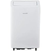
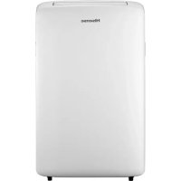
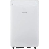
APH12 - Air Conditioning HISENSE - Free user manual and instructions
Find the device manual for free APH12 HISENSE in PDF.
| Product Type | Mobile monobloc air conditioner |
| Brand | Hisense |
| Model | APH12 |
| Refrigerant | R32 (flammable) |
| Power supply | 220-240 V ~ 50 Hz |
| Recommended electrical protection | 20 A fuse or circuit breaker |
| Required plug | 3-pin grounded plug |
| Operating modes | Cooling, Dehumidifying, Ventilation, Heating (reversible models) |
| Special functions | Smart, Sleep, Super, I Feel, Dimmer, Timer, Swing |
| Temperature range (cooling) | 16 °C to 30 °C |
| Temperature range (heating) | 16 °C to 30 °C |
| Fan speeds | Auto, High, Medium, Low |
| Plasma generator (ION) | Optional depending on model |
| Remote control | With AAA batteries (LR03), max range 7 m |
| Installation kit included | Sliding window kit, exhaust hose, adapters, sealing foam, rain cover |
| Sliding kit dimensions | Adjustable length from 60 cm to 163 cm |
| Minimum room volume | 10 m² |
| Routine maintenance | Clean air filter every 2 weeks, drain water tank if necessary |
| Safety | Safety device for flammable refrigerant, automatic shutdown if tank full (code E5) |
| Weight | Approximately 30 kg (estimate) |
| Dimensions (approx.) | Height: 70 cm, Width: 45 cm, Depth: 35 cm |
Frequently Asked Questions - APH12 HISENSE
User questions about APH12 HISENSE
0 question about this device. Answer the ones you know or ask your own.
Ask a new question about this device
Download the instructions for your Air Conditioning in PDF format for free! Find your manual APH12 - HISENSE and take your electronic device back in hand. On this page are published all the documents necessary for the use of your device. APH12 by HISENSE.
USER MANUAL APH12 HISENSE
USE AND INSTALLATION INSTRUCTIONS
Thank you very much for purchasing this Air Conditioner. Please read this use and installation instructions carefully before installing and using this appliance and keep this manual for future reference.
TABLE OF CONTENTS
SAFETY PRECAUTIONS....2
IDENTIFICATION OF PARTS....10
AIR CONDITIONER SAFETY....11
INSTALLATION REQUIREMENTS....11
Tools and Parts....11
Location Requirements....12
Electrical Requirements....12
INSTALLATION INSTRUCTIONS....12
Unpack the Air Conditioner....12
Install Local Air Conditioner(on the window) 14
Complete Installation....15
Install AirConditioner (through the wall) 16
LOCAL AIR CONDITIONER USE....17
Starting Your Local Air Conditioner....17
Using the Remote Control....18
Normal Sounds....22
Draining the Air Conditioner....23
Cleaning the Outside....23
Cleaning the Air Filter....23
Storing After Use....23
TROUBLESHOOTING....24
SAFETY INSTRUCTIONS
This appliance can be used by children aged from 8 years and above and persons with reduced physical, sensory or mental capabilities or lack of experience and knowledge if they have been given supervision or instruction concerning use of the appliance in a safe way and understand the hazards involved. Children shall not play with the appliance. Cleaning and user maintenanceshall not be made by children without supervision.
Children should be supervised to ensure that they do not play with the appliance. If the supply cord is damaged, it must be replaced by the manufacturer, its service agent or similarly qualified persons in order to avoid a hazard.
The range of external static pressures is -0.2Pa to 0.2Pa.
Keep the unit 5m or more apart from combustible surfaces.
SAFEGUARDING THE ENVIRONMENT
This appliance is made of recyclable or re-usable material. Scrapping must be carried out in compliance with local waste disposal regulations. Before scrapping it, make sure to cut off the mains cord so that the appliance cannot be re-used.
For more detailed information on handling and recycling this product, contact your local authorities who deal with the separate collection of rubbish or the shop where you bought the appliance.
SCRAPPING OF APPLIANCE
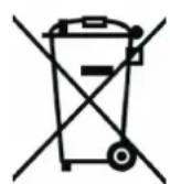
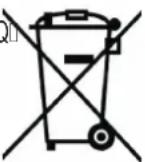
This appliance is marked according to the European Directive 2002/96/EC, Waste Electrical and Electronic Equipment (WEEE).
This marking indicates that this product should not be disposed with other household wastes throughout the EU. To prevent possible harm to the environment or human health from uncontrolled waste disposal, recycle it responsibly to promote the sustainable reuse of material resources. To return your used device, please use the return and collection systems or contact the retailer where the product was purchased.
They can take this product for environmental safe recycling.

Safety precautions
Precautions for using R32 refrigerant
The basic installation work procedures are the same as the conventional refrigerant (R22 or R410A).
However, pay attention to the following points:

CAUTION
- Transport of equipment containing flammable refrigerants
Compliance with the transport regulations
- Marking of equipment using signs
Compliance with local regulations
- Disposal of equipment using flammable refrigerants
Compliance with national regulations
- Storage of equipment/appliances
The storage of equipment should be in accordance with the manufacturer's instructions.
- Storage of packed (unsold) equipment
- Storage package protection should be constructed such that mechanical damage to the equipment inside the package will not cause a leak of the refrigerant charge.
- The maximum number of pieces of equipment permitted to be stored together will be determined by local regulations.
- Information on servicing
6-1 Checks to the area
Prior to beginning work on systems containing flammable refrigerants, safety checks are necessary to ensure that the risk of ignition is minimised. For repair to the refrigerating system, the following precautions shall be complied with prior to conducting work on the system.
6-2 Work procedure
Work shall be undertaken under a controlled procedure so as to minimise the risk of flammable gas or vapour being present while the work is being performed.
6-3 General work area
- All maintenance staff and others working in the local area shall be instructed on the nature of work being carried out. Work in confined spaces shall be avoided.
- The area around the workspace shall be sectioned off. Ensure that the conditions within the area have been made safe by control of flammable material.
6-4 Checking for presence of refrigerant
- The area shall be checked with an appropriate refrigerant detector prior to and during work, to ensure the technician is aware of potentially flammable atmospheres.
- Ensure that the leak detection equipment being used is suitable for use with flammable refrigerants, i.e. non-sparking, adequately sealed or intrinsically safe.

CAUTION
6-5 Presence of fire extinguisher
- If any hot work is to be conducted on the refrigeration equipment or any associated parts, appropriate fire extinguishing equipment shall be available to hand.
- Have a dry powder or CO2 fire extinguisher adjacent to the charging area.
6-6 No ignition sources
- No person carrying out work in relation to a refrigeration system which involves exposing any pipe work that contains or has contained flammable refrigerant shall use any sources of ignition in such a manner that it may lead to the risk of fire or explosion.
- All possible ignition sources, including cigarette smoking, should be kept sufficiently far away from the site of installation, repairing, removing and disposal, during which flammable refrigerant can possibly be released to the surrounding space.
- Prior to work taking place, the area around the equipment is to be surveyed to make sure that there are no flammable hazards or ignition risks. "No Smoking" signs shall be displayed.
6-7 Ventilated area
- Ensure that the area is in the open or that it is adequately ventilated before breaking into the system or conducting any hot work.
- A degree of ventilation shall continue during the period that the work is carried out.
- The ventilation should safely disperse any released refrigerant and preferably expel it externally into the atmosphere.
6-8 Checks to the refrigeration equipment
- Where electrical components are being changed, they shall be fit for the purpose and to the correct specification.
- At all times the manufacturer's maintenance and service guidelines shall be followed. If in doubt consult the manufacturer's technical department for assistance.
- The following checks shall be applied to installations using flammable refrigerants:
- The charge size is in accordance with the room size within which the refrigerant containing parts are installed;
- The ventilation machinery and outlets are operating adequately and are not obstructed;
- If an indirect refrigerating circuit is being used, the secondary circuit shall be checked for the presence of refrigerant;
- Marking to the equipment continues to be visible and legible. Markings and signs that are illegible shall be corrected;
- Refrigeration pipe or components are installed in a position where they are unlikely to be exposed to any substance which may corrode refrigerant containing components, unless the components are constructed of materials

CAUTION
which are inherently resistant to being corroded or are suitably protected against being so corroded.
6-9 Checks to electrical devices
- Repair and maintenance to electrical components shall include initial safety checks and component inspection procedures.
- If a fault exists that could compromise safety, then no electrical supply shall be connected to the circuit until it is satisfactorily dealt with.
- If the fault cannot be corrected immediately but it is necessary to continue operation, an adequate temporary solution shall be used.
• This shall be reported to the owner of the equipment so all parties are advised. - Initial safety checks shall include:
- That capacitors are discharged: this shall be done in a safe manner to avoid possibility of sparking;
- That there no live electrical components and wiring are exposed while charging, recovering or purging the system;
- That there is continuity of earth bonding.
7. Repairs to sealed components
- During repairs to sealed components, all electrical supplies shall be disconnected from the equipment being worked upon prior to any removal of sealed covers, etc.
- If it is absolutely necessary to have an electrical supply to equipment during servicing, then a permanently operating form of leak detection shall be located at the most critical point to warn of a potentially hazardous situation.
- Particular attention shall be paid to the following to ensure that by working on electrical components, the casing is not altered in such a way that the level of protection is affected.
- This shall include damage to cables, excessive number of connections, terminals not made to original specification, damage to seals, incorrect fitting of glands, etc.
- Ensure that apparatus is mounted securely.
- Ensure that seals or sealing materials have not degraded such that they no longer serve the purpose of preventing the ingress of flammable atmospheres.
- Replacement parts shall be in accordance with the manufacturer's specifications.
NOTE:
The use of silicon sealant may inhibit the effectiveness of some types of leak detection equipment. Intrinsically safe components do not have to be isolated prior to working on them.
8. Repair to intrinsically safe components
- Do not apply any permanent inductive or capacitance loads to the circuit without ensuring that this will not exceed the permissible voltage and current permitted for the equipment in use.
- Intrinsically safe components are the only types that can be worked on while
Safety precautions

CAUTION
live in the presence of a flammable atmosphere. The test apparatus shall be at the correct rating.
- Replace components only with parts specified by the manufacturer.
- Other parts may result in the ignition of refrigerant in the atmosphere from a leak.
9. Cabling
- Check that cabling will not be subject to wear, corrosion, excessive pressure, vibration, sharp edges or any other adverse environmental effects.
- The check shall also take into account the effects of aging or continual vibration from sources such as compressors or fans.
10. Detection of flammable refrigerants
- Under no circumstances shall potential sources of ignition be used in the searching for or detection of refrigerant leaks.
- A halide torch (or any other detector using a naked flame) shall not be used.
11.Leak detection methods
- The following leak detection methods are deemed acceptable for systems containing flammable refrigerants:
- Electronic leak detectors shall be used to detect flammable refrigerants, but the sensitivity may not be adequate, or may need re-calibration. (Detection equipment shall be calibrated in a refrigerant-free area.)
- Ensure that the detector is not a potential source of ignition and is suitable for the refrigerant used.
- Leak detection equipment shall be set at a percentage of the LFL of the refrigerant and shall be calibrated to the refrigerant employed and the appropriate percentage of gas (25 % maximum) is confirmed.
- Leak detection fluids are suitable for use with most refrigerants but the use of detergents containing chlorine shall be avoided as the chlorine may react with the refrigerant and corrode the copper pipe-work.
- If a leak is suspected, all naked flames shall be removed/ extinguished.
- If a leakage of refrigerant is found which requires brazing, all of the refrigerant shall be recovered from the system, or isolated (by means of shut off valves) in a part of the system remote from the leak.
- Oxygen free nitrogen (OFN) shall then be purged through the system both before and during the brazing process.
12. Removal and evacuation
- When breaking into the refrigerant circuit to make repairs – or for any other purpose – conventional procedures shall be used.
- However, it is important that best practice is followed since flammability is a consideration.
• The following procedure shall be adhered to: - Remove refrigerant;
– Purge the circuit with inert gas;
Safety precautions

CAUTION
- Evacuate;
– Purge again with inert gas;
- Open the circuit by cutting or brazing.
- The refrigerant charge shall be recovered into the correct recovery cylinders.
- The system shall be "flushed" with OFN to render the unit safe.
• This process may need to be repeated several times.
- Compressed air or oxygen shall not be used for this task.
- Flushing shall be achieved by breaking the vacuum in the system with OFN and continuing to fill until the working pressure is achieved, then venting to atmosphere, and finally pulling down to a vacuum.
- This process shall be repeated until no refrigerant is within the system. When the final OFN charge is used, the system shall be vented down to atmospheric pressure to enable work to take place.
- This operation is absolutely vital if brazing operations on the pipe-work are to take place.
- Ensure that the outlet for the vacuum pump is not close to any ignition sources and there is ventilation available.
13. Charging procedures
- In addition to conventional charging procedures, the following requirements shall be followed:
- Ensure that contamination of different refrigerants does not occur when using charging equipment.
- Hoses or lines shall be as short as possible to minimise the amount of refrigerant contained in them.
– Cylinders shall be kept upright.
- Ensure that the refrigeration system is earthed prior to charging the system with refrigerant.
- Label the system when charging is complete (if not already).
- Extreme care shall be taken not to overfill the refrigeration system.
- Prior to recharging the system it shall be pressure tested with OFN.
- The system shall be leak tested on completion of charging but prior to commissioning.
• A follow up leak test shall be carried out prior to leaving the site.
14. Decommissioning
- Before carrying out this procedure, it is essential that the technician is completely familiar with the equipment and all its detail.
- It is recommended good practice that all refrigerants are recovered safely.
- Prior to the task being carried out, an oil and refrigerant sample shall be taken in case analysis is required prior to re-use of reclaimed refrigerant. It is essential that electrical power is available before the task is commenced.
a) Become familiar with the equipment and its operation.
b) Isolate system electrically.
Safety precautions

CAUTION
c) Before attempting the procedure ensure that:
- Mechanical handling equipment is available, if required, for handling refrigerant cylinders;
- All personal protective equipment is available and being used correctly;
- The recovery process is supervised at all times by a competent person;
– Recovery equipment and cylinders conform to the appropriate standards.
d) Pump down refrigerant system, if possible.
e) If a vacuum is not possible, make a manifold so that refrigerant can be removed from various parts of the system.
f) Make sure that cylinder is situated on the scales before recovery takes place.
g) Start the recovery machine and operate in accordance with manufacturer's instructions.
h) Do not overfill cylinders. (No more than 80 % volume liquid charge).
I) Do not exceed the maximum working pressure of the cylinder, even temporarily.
j) When the cylinders have been filled correctly and the process completed, make sure that the cylinders and the equipment are removed from site promptly and all isolation valves on the equipment are closed off.
k) Recovered refrigerant shall not be charged into another refrigeration system unless it has been cleaned and checked.
15. Labelling
- Equipment shall be labelled stating that it has been de-commissioned and emptied of refrigerant.
• The label shall be dated and signed. - Ensure that there are labels on the equipment stating the equipment contains flammable refrigerant.
16.Recovery
- When removing refrigerant from a system, either for servicing or decommissioning, it is recommended good practice that all refrigerants are removed safely.
- When transferring refrigerant into cylinders, ensure that only appropriate refrigerant recovery cylinders are employed.
- Ensure that the correct number of cylinders for holding the total system charge is available.
- All cylinders to be used are designated for the recovered refrigerant and labelled for that refrigerant (i.e. special cylinders for the recovery of refrigerant).
- Cylinders shall be complete with pressure relief valve and associated shut-off valves in good working order.
- Empty recovery cylinders are evacuated and, if possible, cooled before recovery occurs.
- The recovery equipment shall be in good working order with a set of
Safety precautions

CAUTION
instructions concerning the equipment that is at hand and shall be suitable for the recovery of flammable refrigerants.
- In addition, a set of calibrated weighing scales shall be available and in good working order.
- Hoses shall be complete with leak-free disconnect couplings and in good condition.
- Before using the recovery machine, check that it is in satisfactory working order, has been properly maintained and that any associated electrical components are sealed to prevent ignition in the event of a refrigerant release.
- Consult manufacturer if in doubt.
• The recovered refrigerant shall be returned to the refrigerant supplier in the correct recovery cylinder, and the relevant Waste Transfer Note arranged.
• Do not mix refrigerants in recovery units and especially not in cylinders. - If compressors or compressor oils are to be removed, ensure that they have been evacuated to an acceptable level to make certain that flammable refrigerant does not remain within the lubricant.
• The evacuation process shall be carried out prior to returning the compressor to the suppliers. - Only electric heating to the compressor body shall be employed to accelerate this process.
- When oil is drained from a system, it shall be carried out safely.

CAUTION
- When moving or relocating the air conditioner, consult experienced service technicians for disconnection and reinstallation of the unit.
- Do not place any other electrical products or household belongings under indoor unit or outdoor unit. Condensation dripping from the unit might get them wet, and may cause damage or malfunction of your property.
- Do not use means to accelerate the defrosting process or to clean, other than those recommended by the manufacturer.
- The appliance shall be stored in a room without continuously operating ignition sources (for example, open flames, an operating gas appliance or an operating electric heater).
- Do not pierce or burn.
- Be aware that refrigerants may not contain an odor.
• To keep ventilation openings clear of obstruction. - The appliance shall be stored in a well-ventilated area where the room size corresponds to the room area as specified for operation.
- The appliance shall be stored in a room without continuously operating open flames (for example an operating gas appliance) and ignition sources (for example an operating electric heater).
Safety precautions

CAUTION
- Any person who is involved with working on or breaking into a refrigerant circuit should hold a current valid certificate from an industry-accredited assessment authority, which authorises their competence to handle refrigerants safely in accordance with an industry recognised assessment specification.
- Servicing shall only be performed as recommended by the equipment manufacturer.
- Maintenance and repair requiring the assistance of other skilled personnel shall be carried out under the supervision of the person competent in the use of flammable refrigerants.
- Do not use means to accelerate the defrosting process or to clean, other than those recommended by the manufacturer.
- Appliance shall be installed, operated and stored in a room with a floor area larger than 10 m. ^2
- The installation of pipe-work shall be kept to a room with a floor area larger than 10m^2 .
• The pipe-work shall be complianced with national gas regulations.
• The maximum refrigerant charge amount is 2.5 kg. - Mechanical connectors used indoors shall comply with ISO 14903. When mechanical connectors are reused indoors, sealing parts shall be renewed. When flared joints are reused indoors, the flare part shall be re-fabricated.
• The installation of pipe-work shall be kept to a minimum. - Mechanical connections shall be accessible for maintenance purposes.
Explanation of symbols displayed on the indoor unit or outdoor unit.
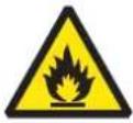 | WARNING | This symbol shows that this appliance uses a flammable refrigerant.If the refrigerant is leaked and exposed to an external ignition source, there is a risk of fire |
 | CAUTION | This symbol shows that the operation manual should be read carefully. |
 | CAUTION | This symbol shows that a service personnel should be handling this equipment with reference to the installation manual. |
 | CAUTION | This symbol shows that information is available such as the operating manual or installation manual. |
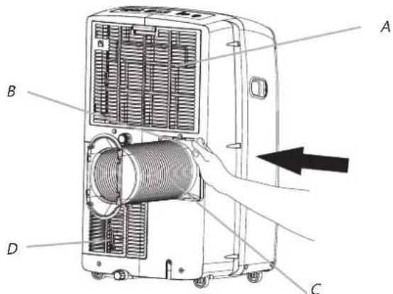
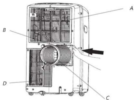
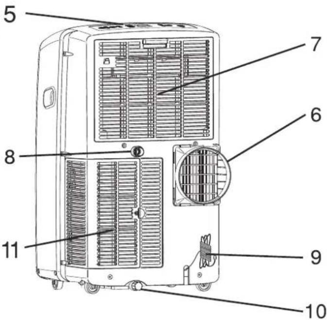
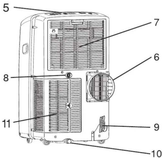
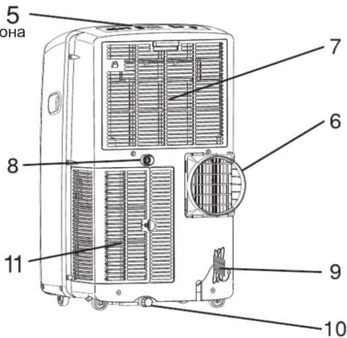
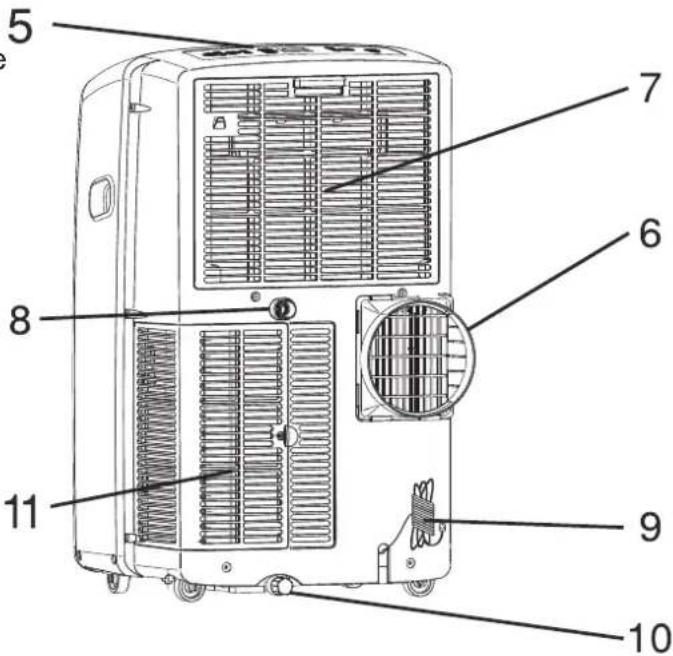
IDENTIFICATION OF PARTS
- Front
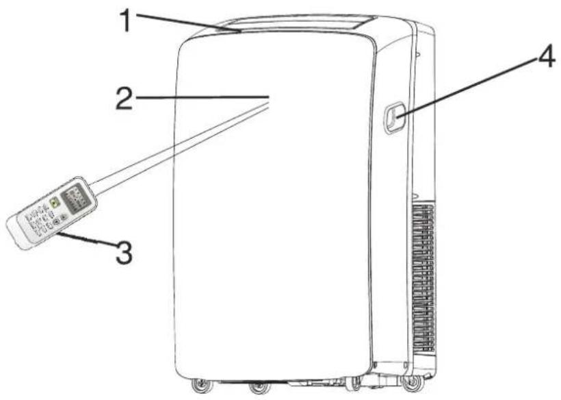
text_image
Diagram of a portable air conditioner unit with labeled parts including a remote control and indicator lights- Back
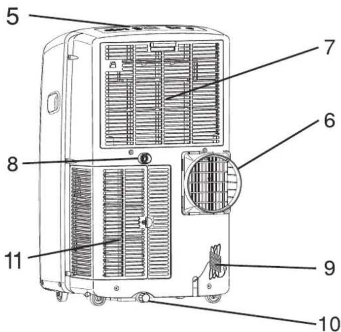
text_image
Technical diagram of an air conditioner unit with numbered parts labeled for identification.
The figures in this manual are based on the external view of a standard model.
They may differ from that of the air conditioner you have selected.
1 Cool air outlet
2 Signal receptor
3 Remote control
4 Transport handle
5 Control panel
6 Air outlet hose
7 Evaporator air intake
8 Secondary drain port
9 Power supply
10 Primary drain port
11 Condenser air intake
AIR CONDITIONER SAFETY
You safety and the safety of others are very important.
We have provided many important safety messages in this manual and on your appliance. Always read and obey all safety messages.

This is the safety alert symbol.
This symbol alerts you to potential hazards that can kill or hurt you and others.
All safety messages will follow the safety alert symbol and either the word "DANGER" or "WARNING".
These words mean:
DANGER
WARNING
You can be killed or seriously injured if you don't immediately follow instructions.
You can be killed or seriously injured if you don't follow instructions.
All safety messages will tell you what the potential hazard is, tell you how to reduce the chance of injury, and tell you what can happen if the instructions are not followed.
IMPORTANT SAFETY INSTRUCTIONS
WARNING: To reduce the risk of fire, electrical shock or injury when using your air conditioner, follow these basic precautions:
■ Plug into a grounded 3 prong outlet.
■ Do not remove ground prong.
■ Do not use an adapter.
■ Do not use an extension cord.
■ Unplug air conditioner before servicing.
■ Use two or more people to move and install air conditioner.
SAVE THESE INSTRUCTIONS
DISPOSING OF THE UNIT
■ Before throwing the device, it is necessary to pull back the battery cells and get rid of them safety for recycling reasons.
■When you need to disposal of the unit consult our dealer. If pipes are removed incorrectly, refrigerant may blow out and come into contact with your skin, causing injury. Releasing refrigerant into the atmosphere also damages the environments. please recycle or dispose of the packaging material for product in an environmentally responsible manner.
■ Never store or ship the air conditioner upside down or sideways to avoid damage to the compressor.
■ The appliance is not intended for use by young children or infirm persons without supervision. Young children should be supervised to ensure that they do not play with the appliance.
INSTALLATION REQUIREMENTS
Tools and Parts
Gather the required tools and parts before starting installation. Read and follow the instructions provided with any tools listed here.
Tools needed
Phillips screwdriver
■ Saw
■ Pencil
Scissors
■ Cordless drill and 18 " bit
Parts needed
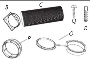
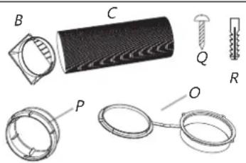
The company provides only one plan to install local air conditioner: See "Install Local Air Conditioner"(P4-P8)
PLAN 1:
text_image
N 1: A C D E F G B I H L K M N JPLAN 2:(optional)
natural_image
Technical illustration of mechanical components including a cylindrical component, threaded fastener, and ring-like parts (no text or symbols)A.Foam seal
B. Dummy coupling
C.Flexible exhaust hose
D. Window exhaust adapter
E. 1/2 "screws (2)
F. Wood screws(4)
G. Window-lock bracket(2)
H. Rain coverl.
I. Outer slider section
J. Inner slider section
K. Bolts (4)
L. Nuts (4)
M. Spring washers (4)
N.Plain washers (4)
O.Wall cover
P. Exhaust adapter
Q.Long Wood screws(3)
R.Plastics plug(3)
Location Requirements
NOTES:
■ The flexible exhaust hose allows placement of the air conditioner between 60 cm and 170 cm from window or door. For appliances with supplementary heaters, the minimum clearance from the appliances to combustible surfaces is 100cm.
■ Local air conditioners are designed as supplemental cooling to local areas within a room.
Vertical Slide Widow
text_image
Slide Widow combustible surfaces 100cm 60 cm 170 cmHorizontal Slide Window
text_image
Metal Slide Window combustible surfaces 100cm 60 cm - 170 cmNOTES:
■ To ensure proper ventilation, keep the required distance from the return air outlet to the wall or other obstacles at least 23% (60 cm).
■ Do not block the air outlet.
■ Provide easy access to the grounded 3 prong outlet.
Electrical Requirements
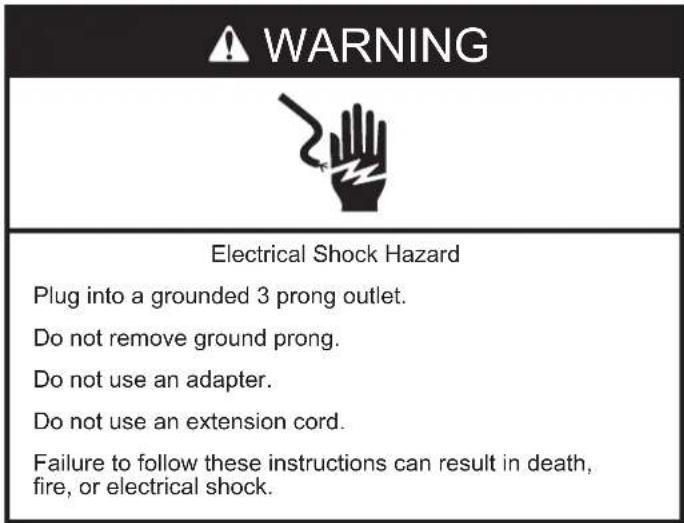
WARNING
Electrical Shock Hazard
Plug into a grounded 3 prong outlet.
Do not remove ground prong.
Do not use an adapter.
Do not use an extension cord.
Failure to follow these instructions can result in death, fire, or electrical shock.
■ The loaconditioner should be connected to a 220V-240, 50 HZ, 20-amp fuse grounded 3 prong outlet.
■ The use of a time-delay fuse or time-delay circuit breaker is recommended.
All wiring must comply with local and the national electrical codes and be installed by a qualified electrician. If you have any questions, contact a qualified electrician.
INSTALLATION INSTRUCTIONS
Unpack the Air Conditioner
WARNING
Excessive Weight Hazard
Use two or more people to move and install air conditioner.
Failure to do so can result in back or other injury.
Remove packaging materials
■ Remove and dispose of/recycle packaging materials.
■ Remove tape and glue residue from surfaces before turning on the air conditioner. Rub a small amount of liquid dish soap over the adhesive with your fingers. Wipe with warm water and dry.
- Do not use sharp instruments, rubbing alcohol, flammable fluids, or abrasive cleaners to remove tape or glue. These products can damage the surface of your air conditioner.
■ Handle the air conditioner gently.
Install Exhaust Hose and Adapter
- Roll the air conditioner to selected location. see "Location Requirements."
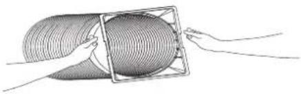
- Attach the dummy coupling to the flexible exhaust hose. Turn anticlockwise until securely locked into place.
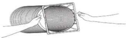
natural_image
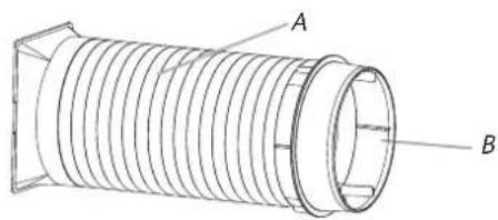
Illustration of a coiled tube being handled with two hands (no text or symbols)- Attach the window exhaust adapter to the flexible exhaust hose. Turn anticlockwise until securely locked into place.
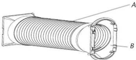
natural_image
Technical line drawing of a coiled spring or hose assembly with labeled components A and B (no text or symbols beyond labels)A. Flexible exhaust hose
B. Window exhaust adapter
-
Insert the dummy coupling into the slot on the back of the air conditioner.
-
Slide down to lock the hose into place.
text_image
A B D CA. Evaporator air intake
B. Dummy coupling
C. Flexible exhaust hose
D. Condenser air intake
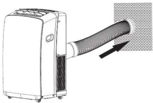
Window Installation
Your window slider kit has been designed to fit most standard vertical and horizontal window applications. Roll the air conditioner to selected location. see "Location Requirements."
- Insert the windows exhaust adapter into the slot on the window slider kit.
text_image
A BA. Window slider kit
B. Window exhaust adapter
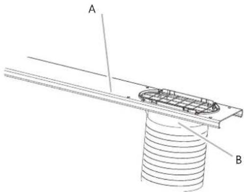
- Using the 2 bolts, washer and nuts (provided), attach the rain cover to the window slider kit for either the vertical or horizontal installation.
NOTES:
■ The holes in the window slider kit are positioned for attaching the rain cover for vertical or horizontal installation.
■ Insert the other 2 bolts, washers and nuts (provided) into the unused holes in the window slider kit to keep moisture from leaking through the window slider kit.
Rain cover--Vertical Installation
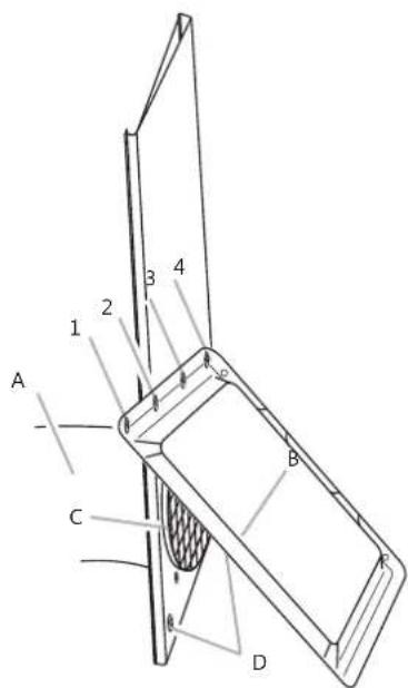
text_image
A 1 2 3 4 B C DA. Window exhaust adapter
B. Rain cover
C. Outlet grille
D. Bolts inserted into unused holes in Window slider kit
NOTES: Four holes in the rain cover for vertical installation. Insert the 2 bolts with "1" "3" or "2" "4".
Rain cover--Horizontal Installation
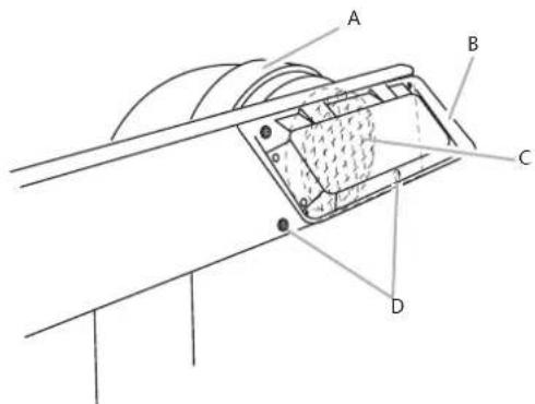
text_image
Technical diagram of a mechanical assembly with labeled components A, B, C, and DA. Window exhaust adapter
D. Bolts inserted into unused holes in Window slider kit
B. Rain cover
C. Outlet grille
-
Open the window.
-
Measure the window opening.
■ If the window opening is too narrow for the window slider kit, remove the inner slider section from the window slider kit.
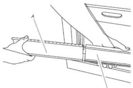
text_image
AA. Inner slider section
B. Outer slider section
■ Using a saw, cut the inner slider section to fit the window opening.
■ Slide the inner slider section into the outer slider section of the window slider kit.
- Place the window slider kit into the window, extending it to fit the width of the window. Be sure the rain cover is on the outside of the window.
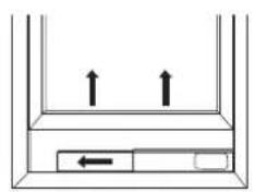
natural_image
Simple line drawing of a container with two upward arrows and one left-pointing arrow inside (no text or symbols)
natural_image
Simple line drawing of a container with two downward arrows and a textured base (no text or symbols)NOTE: For casement window installation, the window slider kit may be installed vertically with the window slider kit opening at the bottom.
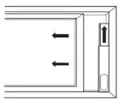
natural_image
Simple line drawing of a door with two arrows indicating left and right motion (no text or symbols)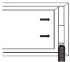
natural_image
Simple line drawing of a door frame with two arrows pointing outward and a small cylindrical object on the side (no text or symbols)- Inset 12 " screw (provide 2) into the hole in the inner slider section that is closest to the end of the outer slider section of
text_image
A B CA. 12 "screw (provide 2)
B. Inner slider section
C. Outer slider section
- Close the window onto the window slider kit to secure.
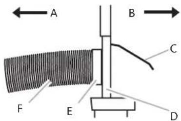
text_image
A B C F E DA. To local air conditioner
B. Outdoors
C. Rain cover
D. Window slider kit
E. Window exhaust adapter
F. Flexible exhaust hose
Complete Installation
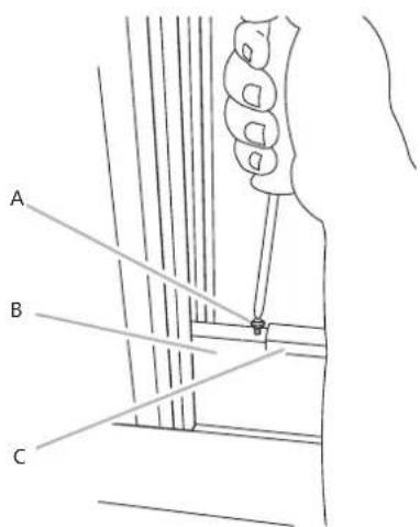
- Place the window-lock bracket on top of the lower window and against the upper window sash.
- Use 1/8" drill bit to drill a starter hole through the hole in the bracket.
- Attach the window-lock bracket to the window sash with wood screw(provide 4) to secure the window in place.
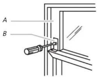
text_image
A BA. Upper window sash
B. Window-lock bracket
- Insert the foam seal behind the top of the lower window sash and against the glass of the upper window.
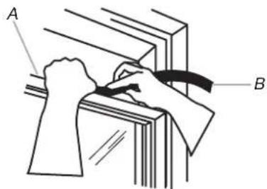
text_image
A BA. Top of lower window sash
B. Foam seal
text_image
WARNING Electrical Shock Hazard Plug into a grounded 3 prong outlet. Do not remove ground prong. Do not use an adapter. Do not use an extension cord. Failure to follow these instructions can result in death, fire, or electrical shock.- Plug into a grounded 3 prong outlet.
Install Local Air Conditioner(through the wall)
Install Exhaust Hose and Adapter
- Roll the air conditioner to selected location. see "Location Requirements."
- Attach the dummy coupling to the flexible exhaust hose. Turn anticlockwise until securely locked into place.
natural_image
Illustration of a coiled tube being handled with a transparent frame, no text or symbols present- Attach the window exhaust adapter to the flexible exhaust hose. Turn anticlockwise until securely locked into place.
text_image
A BA. Flexible exhaust hose
B. Wall exhaust adapter
- Insert the dummy coupling into the slot on the back of the air conditioner.
- Slide down to lock the hose into place.
text_image
A B D CA. Evaporator air intake
B. Dummy coupling
C. Flexible exhaust hose
D. Condenser air intake
Drill a Hole for wall cover
- Decide the position of hole for wall cover according to the location of mounting plate.
- Drill a hole on the wall. The hole should a little bigger than wall cover.
- Install wall cover through the wall hole to keep the wall tidy and clean, fixed with four screws.

text_image
Indoor Outdoor Wall hole (prepared by user)Insert the wall exhaust adapter to wall cover
- Insert the dummy coupling into the wall cover on the wall.
natural_image
Diagram of a portable air conditioner unit with a hose inserted, showing airflow direction (no text or symbols)Insert the wall exhaust adapter to wall cover
- Remove wall exhaust adapter from the wall cover.
2.Cover the wall cover.
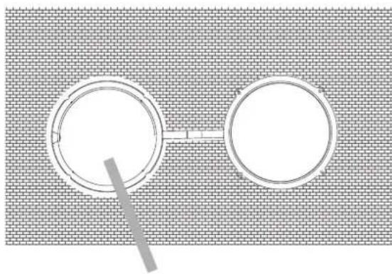
natural_image
Two circular objects connected by a line, placed on a textured surface (no text or symbols)Cover
Operating your local air conditioner properly helps you to obtain the best possible results.
This section explains proper air conditioner operation.
IMPORTANT:
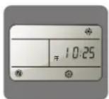
■ The air conditioner display shows the current room temperature.
■ When changing modes while the air conditioner is operation, the compressor will stop for 3 to 5 minutes before restarting.
■If a button is pressed during this time, the compressor will not restart fo another 3 to 5 minutes.
■In Cooling or Dry mode, the compressor and condenser fan will stop when the room temperature reaches the set temperature.
NOTE: In the event of a power failure, your air conditioner will operate at the previous settings when the power is restored.
Starting Your Local Air Conditioner
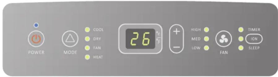
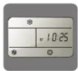
text_image
POWER MODE COOL DRY FAN HEAT 26°C - HIGH MED LOW FAN TIMER ION SLEEPNOTE: The symbols may be different from these models, but the functions are similar.
- Select the mode. See "MODE".
- Select the fan speed. See "FAN".
- Set the temperature. See "TEMPERATURE".
- Press POWER button to start the air conditioner.

POWER
NOTE:
When the air conditioner is turned on, it will run according to the previous setting.
Only if the unit is operated in UNLIKELY VERY HUMID air, water will be collected in the container inside the unit. If the water container is full, the air conditioner will stop. The screen will displays "E5" to inform you to empty the internal container.
Mode
Operating modes:
- Press and release MODE until you see the symbol flashes for the desired setting.

MODE
- Choose Cooling, Dry, Fan Only or Heating.
Cooling-Cools the room. Press FAN to select High, Mid or Low. Press the Plus or Minus button to adjust the temperature.

COOL
Dry-Dries the room. The air conditioner automatically selects the temperature. The fan runs on Low speed only.
NOTE: Dry mode should not be used to cool the room.

DRY
Fan Only-Only the fan runs. Press FAN to select High, Mid or Low.

FAN
Heating-heats the room. Press FAN to select high,
Mid or Low. Press the PLUS or MINUS button to adjust the temperature.
NOTE: Heating is NOT available for cooling only air conditioner.

HEAT
Fan Speed
- Press and release FAN to choose the desired fan speed.

FAN
- Choose High, Mid or Low.
Auto-automatically controls the fan speed depending on the current room temperature and temperature control setting.
High-for maximum fan speed
HIGH

Mid-for normal fan speed
MED

Low-for minimum fan speed
LOW

Temperature
Press the PLUS button to raise the temperature. Press the PLUS button once to increase the set temperature by 1°C.

Press the MINUS button to lower the temperature. Press the MINUS button once to decrease the set temperature by 1°C.

NOTE:
In the Cooling mode, the temperature can be set between 16^ C and 30^ C.
In Fan Only mode, the temperature cannot be set.
ION (Optional)
Press the ION button to start or stop the Plasma Generator.

When the ION indicator light of the appliance flashes, the Plasma Generator will turn on.
Using the Remote Control
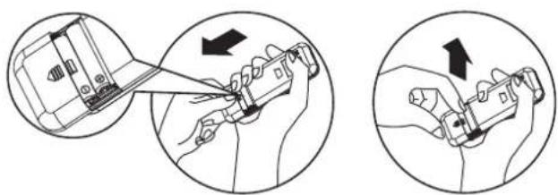
Insert the Batteries
- Remove the battery cover to the arrow direction.
natural_image
Illustration showing two hand positions: one with a device being inserted, the other holding a tool (no text or symbols present)-
Insert new batteries making sure that the (+) and (-) of battery are matched correctly.
-
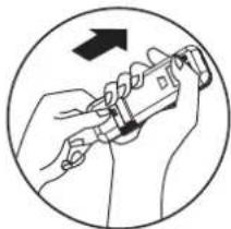
Reattach the cover by sliding it back into position.
natural_image
Illustration of hands using a tool to adjust or install a component, enclosed in a circle with an arrow indicating rotation (no text or symbols present)NOTE:
- Use 2 LR03 AAA(1.5volt) batteries. Do not use rechargeable batteries. Replace batteries with new ones of the same type when the display becomes dim, or after 6 months.
- If you reload batteries over after removing the old ones, you will miss the presetting and the timer will go back to Zero.
Storage trip
The clip on the back of the unit can be used to store the remote control.
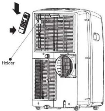
text_image
HolderHow to Use
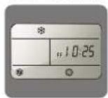
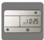
To operate the room air conditioner, aim the remote controller to the signal receptor. The remote control will operate the air conditioner at a distance of up to 23' (7m) when pointing at signal receptor of the air conditioner.
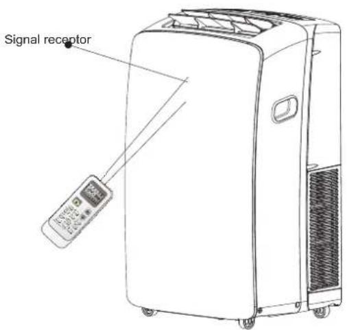
text_image
Signal receptorRemote control
NOTE: Remote control may differ in appearance.
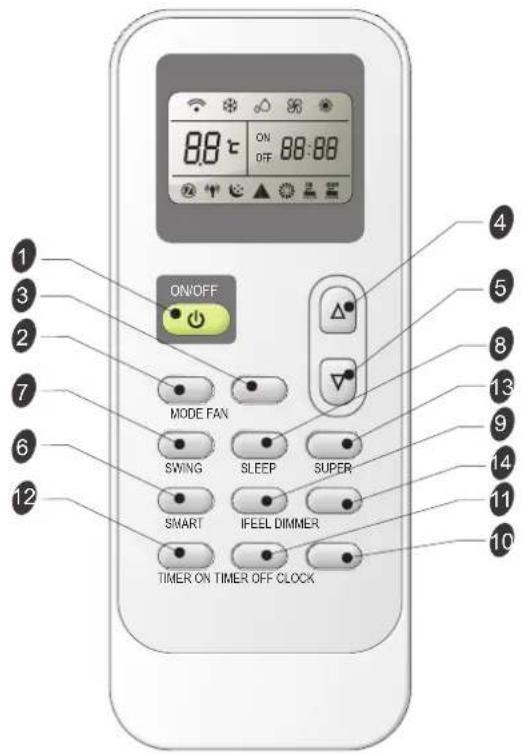
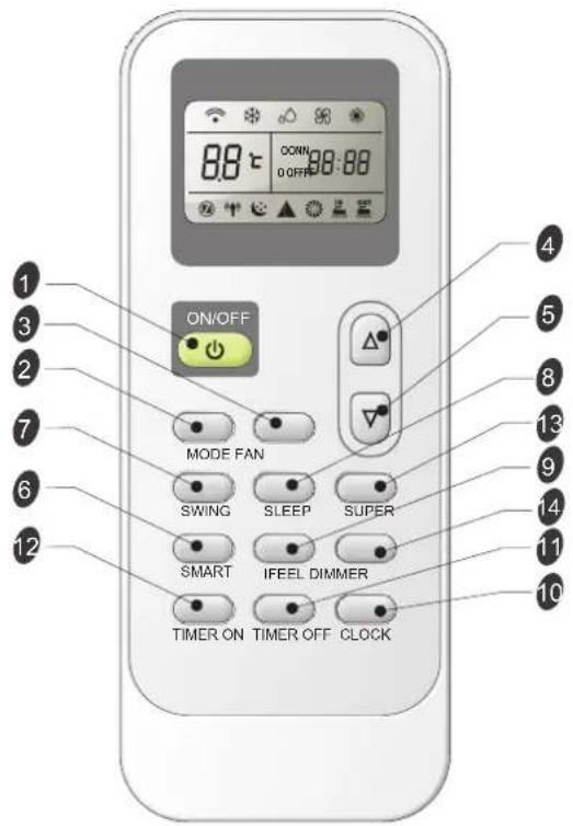
text_image
ON/OFF MODE FAN SWING SLEEP SUPER SMART IFEEL DIMMER TIMER ON TIMER OFF CLOCKButton and Function
| 1 | ON/OFF | ON/OFF | 8 | SLEEP | SLEEP | |
| 2 | MODE | MODE | 9 | IFEEL | IFEEL | |
| 3 | FAN | FAN | 10 | CLOCK | CLOCK | |
| 4 | UP | 11 | TIMER_OFF | Timer Off | ||
| 5 | DOWN | 12 | TIMER_ON | Timer On | ||
| 6 | SMART | SMART | 13 | SUPER | SUPER | |
| 7 | SWING | SWING | 14 | DIMMER | DIMMER |
Indication symbols
Indication symbols on LCD:
| Cooling indicator | Auto fan speed | ||
| Dry indicator | High fan speed | ||
| Fan only indicator | Medium fan speed | ||
| Heating indicator | Low fan speed |
| ▲ Smart indicator | Signal transmit. |
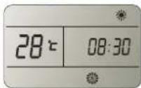
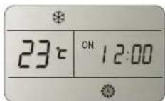
| Sleep indicator | ON OFF 88:88 Display set timer Display current time |
| I feel indicator | |
| Super indicator | 88°C Display set temperature |
Power On or Off
Press ON/OFF button to turn on or off the unit

NOTE: ■ Changing modes during operating. Sometimes the unit does not response at once. Wait 3 minutes.
■ Wait 3 minutes before restarting the appliance.
Mode
- Press MODE repeatedly until you see the symbol flashes for the desired setting.

- Choose Cooling, Dry, Fan Only and heating.
■Cooling-Cools the room. Press FAN to select AUTO, HIGH, MID or LOW.
Press the UP or DOWN button to adjust the temperature.

■ Dry-Dries the room. The air conditioner automatically selects the temperature. The fan runs on Low speed only.
NOTE: Dry mode should not be used to cool the room. A decrease or rise of up to can be set with the remote controller if you still feel uncomfortable.

■ Fan Only-Only the fan runs. Press FAN button to adjust fan speed.

NOTE: Auto fan speed cannot be selected in Fan Only mode.
■ Heating-Heats the room. Press FAN to select the fan speed. Press the up or down TEMP button to adjust the temperature.

SMART Mode
Press the SMART button, Smart mode (fuzzy logic operation) is directly regardless of the unit is on or off. In this mode, temperature and fan speed are automatically set based on the actual room temperature.
To cancel Smart Mode, just press the MODE button.
SMART
Operation mode and temperature are determined by indoor temperature.
With Heater models
| Indoor temperature | Operation mode | Target temperature |
| 21°C or below | HEATING | 22°C |
| 21-23°C | FAN ONLY | |
| 23-26°C | DRY | Room temperature decrease 2 ° after operate for 3 minutes |
| Over 26°C | COOLING | 26°C |
Cooling only models
| Indoor temperature | Operation mode | Target temperature |
| 23°C or below | FAN ONLY | |
| 23-26°C | DRY | Room temperature decrease 2 after operate for 3 minutes |
| Over 26°C | COOLING | 26°C |
NOTE: Temperature, airflow and direction are controlled automatically in smart mode. However, a decrease or rise of up to 250 be set with the remote controller if you still feel uncomfortable.
| What you can do in ▲ mode | ||
| Your feeling | Button | Adjustment |
| Uncomfortable because of unsuitable air flow volume. | Indoor fan speed alternates among High, Medium and Low each time this button is pressed. | |
| Uncomfortable because of unsuitable flow direction. | Press it once, the louver swings to change airflow direction. Press it again, swings stops. | |
SUPER
SUPER button is used to start or stop fast cooling or heating.
- Press SUPER button. The air conditioner automatically sets the fan speed to High and the temperature to 16^ C. Fast heating operates at auto fan speed, changing the set temperature automatically to 30^ C.

- To turn off Super control, press any button on the remote control or control panel except Timer On, Timer Off, Clock, Dimmer, I feel and Swing.
NOTE:
■ In the SUPER mode you can set airflow direction or timer.
■ SMART mode are not available in SUPER mode.
■ SUPER button is ineffective in SMART mode.
fast cooling
fast heating
Fan Speed
- Press FAN button, Choose desired fan speed.

■ Auto-Automatically controls fan speed depending on current room temperature and temperature control setting.
NOTE: Auto fan speed cannot be selected in Fan Only mode.

■ High for maximum fan speed

■ Mid for normal fan speed

■ Low for minimum fan speed

Temperature
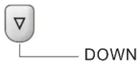
■ Press the UP button to raise the temperature. Press the UP button once to increase the set temperature by 1^ C.
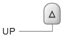
■ Press the DOWN button to lower the temperature. Press the DOWN button once to decrease the set temperature by 1°C.
NOTES:
In the Cooling and Heating mode, the temperature can be set between 16°C and 30°C.
■ In Fan Only mode, the temperature cannot be set.
Sleep mode
SLEEP mode can be set in Cooling, Heating or Dry operation mode. This function gives you a more comfortable environment for sleep.

NOTE:
■ The appliance will stop operation automatically after operating for 8 hours.
■ Fan speed is automatically set at low speed.
In the Cooling mode, if the current room temperature is below 26^ C, the temperature will automatically increase 1^ C during the first hour after Sleep control is activated, then remain the same.
If room temperature is 26^ or above, set temperature will not change.
■ In Heating mode, set temperature will decrease by 3^ C at most for 3 hours constantly, then keeps steady.
- Press MODE to select Cooling, Heating or Dry.
NOTE: Sleep control cannot be selected when Fan Only or SMART is selected. - Press the UP or DOWN button to set the temperature.
- Press SLEEP. After 5 seconds, the lights on the control panel display will dim.
NOTE: The temperature and airflow direction may be adjusted during Sleep control. The fan speed is automatically set to Low speed. After 5 seconds, the lights on the control panel display will dim again.
- To turn off Sleep control, press SLEEP, MODE, FAN, ON/OFF, SUPER or wait 8 hours for Sleep control to turn off automatically.
NOTE: The air conditioner will return to previous settings after Sleep control is turned off.
I FEEL
The temperature sensor built in remote controller is activated. It can sense its surrounding temperature, and transmit the signal back the unit. the unit can adjust the temperature so as to provide maximum comfort.

NOTE:
Used to set IFEEL mode operation. Press it once, the IFEEL function will be started. Press it again, the IFEEL function will be shut off. If the IFEEL function can't be shut off, please try to press this button about 5 seconds.
Advice to put the remote controller in the place where the indoor unit receive signal easily.
Advice to cancel the IFEEL mode so as to save energy when stopping the air conditioner.

DIMMER
Press the DIMMER button to turn off the light and the display in the unit.

NOTE:
■ When the light is off, receive signal will turn on the light again.
Clock function
- You can or adjust the real time by pressing CLOCK button

- Using the Up and Down buttons to get the correct time.
- Press CLOCK button again the real time is set.
TIMER ON/OFF
It is convenient to set the timer on with TIMER ON/OFF buttons before you leave so that you will come back to the comfortable room temperature you set.
NOTE: It is real timer control. you should set the CLOCK first.
To TIMER ON
TIMER ON button can be used to turn on the unit automatically at the time you set.
- Press TIMER ON, Then "On 12:00" flashes on the LCD.

- Press the UP or DOWN button to get your desired time to turn on the appliance.

Increase

Decrease
■ Press the UP or DOWN button once to increase or decrease the time setting by 1 minute.
■ Press and hold the UP or DOWN button for 2 seconds to increase or decrease the time setting by 10 minutes.
■ Press and hold the UP or DOWN button for a longer time to increase or decrease the time setting by 1 hour.
- When your desired time displayed on LCD, press the TIMER ON button to confirm it.
A "Beep" can be heard, "ON" stops flashing. The TIMER indicator on the appliance lights up.
- After your desired time displayed for 5 seconds, the clock will be displayed on the LCD of remote controller instead of the desired time.
To cancel Timer On
Press TIMER ON button again, a "beep" can be heard and the indicator disappears, the TIMER ON mode has been canceled.
NOTE: It is similar to set TIMER OFF, you can make the appliance unit switch off automatically at the time you set.

SWING
Press SWING once to change vertical airflow direction. Press again to stop airflow louver at desired airflow direction.

NOTE:
■ Airflow is automatically adjusted to a certain angle in accordance with the operation mode after turning on the unit.
■ The direction of airflow can be also adjusted to your own requirement by pressing the SWING button.
■ Do not turn the vertical adjustment louvers manually, otherwise malfunctions may occur. if that happens, turn off the unit first and cut off the power supply, then restore power supply again.
Normal Sounds
When your air conditioner is operating normally, you may hear sounds such as:
■ Air movement from the fan.
■ Clicks from the thermostat cycle.
■ Vibrations or noise due to poor wall or window construction.
■ A high-pitched hum or pulsating noise caused by the modern high-efficiency compressor cycling on and off.
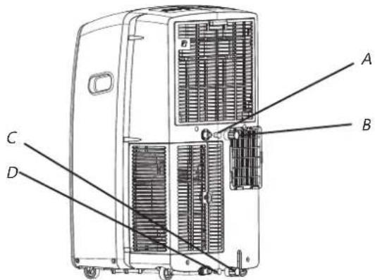
Draining the Air Conditioner
text_image
Technical diagram of a portable air conditioner unit with labeled components A, B, C, and DA. Secondary drain plug
B.Secondary drain cover
C. Primary drain plug
D. Primary drain cover
WARNING
Excessive Weight Hazard
Use two or more people to move and install air conditioner.
Failure to do so can result in back or other injury.
- Unplug the air conditioner or disconnect power.
- Move the air conditioner to a drain location or outside.
NOTE: To avoid spilling water from the bucket, move the air conditioner slowly and keep it level. - Remove the primary drain cover and plug.
- Drain water completely by the drain hole.
NOTE: If the air conditioner will be stored after use, see "Storing After Use".
- Reinstall the drain plug to the primary drain hole.
- Reinstall the primary drain cover to the drain hole.
- Reposition the air conditioner.
- Plug in the air conditioner or reconnect power.
Cleaning the Outside
- Press ON/OFF to turn off the air conditioner.
- Unplug the air conditioner or disconnect power.
- Remove the air filter and clean separately. See "cleaning the Air Filter".
- Wipe the outside of the air conditioner with a soft, damp cloth.
- Plug in the air conditioner or reconnect power.
- Press ON/OFF to start the air conditioner.
Cleaning the Air Filter
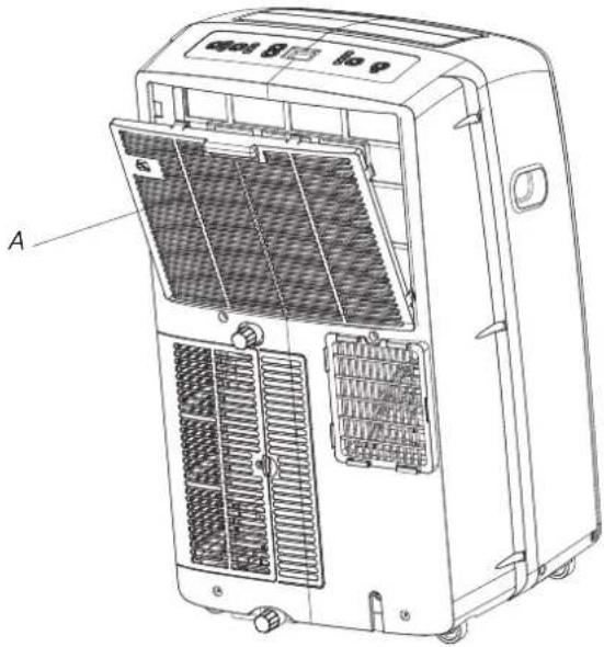
text_image
A cool 8 to 9A. doorEvaporator air intake fliter panel
- Press ON/OFF to turn off the air conditioner.
- Open the filter panel door on the back of the air conditioner and remove.
- Remove the air filter from the filter panel door.
- Use a vacuum cleaner to clean the filter. If the filter is very dirty, wash the filter in warm water with a mild detergent. NOTE: Do not wash the filter in the dishwasher or use any chemical cleaners.
- Air dry the filter completely before replacing to ensure maximum efficiency.
- Reattach the air filter to the filter panel door.
- Reinstall the filter panel door.
- Press ON/OFF to start the air conditioner.
Storing After Use
- Drain the water completely. See "draining the Air Conditioner".
- Run the air conditioner set to Fan Only for approximately 12 hours to dry the air conditioner.
- Unplug the air conditioner.
- Remove the flexible exhaust hose and store with the air conditioner in a clean, dry area. See "installation Instructions".
- Remove the window kit and store with the air conditioner in a clean, dry area. See "Installation Instructions".
- Remove the filter and clean. See Cleaning the Air Filter.
- Clean the outside of the air conditioner. See "Cleaning the Outside".
- Reinstall the filter.
- Remove the batteries and store the remote control with the air conditioner in a clean, dry area.
TROUBLESHOOTING
Before calling for service, try the suggestions below to see whether you can solve your problem without outside help.
Air conditioner will not operate

WARNING

Electrical Shock Hazard
Plug into a grounded 3 prong outlet.
Do not remove ground prong.
Do not use an adapter.
Do not use an extension cord.
Failure to follow these instructions can result in death, fire, or electrical shock.
■ The power supply cord is unplugged.
Plug into a grounded 3 prong outlet. See "electrical Requirements."
■ Time-delay fuse or circuit breaker of the wrong capacity is being used.
Replace with a time-delay fuse or circuit breaker of the correct capacity. See "electrical Requirements".
■ A household fuse has blown, or a circuit breaker has tripped.
Replace the fuse, or reset the circuit breaker. See "Electrical Requirements".
■ The On/Off button has not been pressed.
Press ON/OFF.
■ The local power has failed.
Wait for power to be restored.
Air conditioner blows fuses or trips circuit breakers
■ Too many appliances are being used on the same circuit.
Unplug or relocate appliances that share the same circuit.
■ You are trying to restart the air conditioner too soon after turning off air conditioner.
Wait at least 3 minutes after turning off air conditioner before trying to restart the air conditioner.
■ You have changed modes.
Wait at least 3 minutes after turning off air conditioner before trying to restart the air conditioner.
Air conditioner seems to run too much
■ Is there a door or window open?
Keep doors and windows closed.
■ The current air conditioner replaced an older model.
The use of more efficient components may cause the air conditioner to run longer than an older model, but the total energy consumption will be less. Newer air conditioners do not emit the “blast” of cold air you may be accustomed to from older units, but this is not an indication of lesser cooling capacity or efficiency. Refer to the efficiency rating (EER) and capacity rating (in Btu/h) marked on the air conditioner.
■ The air conditioner is in a heavily occupied room, or heat-producing appliances are in use in the room.
Use exhaust vent fans while cooking or bathing and try not to use heat-producing appliances during the hottest part of the day. Local air conditioners are designed as supplemental cooling to local areas within a room. A higher capacity air conditioner may be required, depending on the size of the room being cooled.
Air conditioner runs for a short time only, but room is not cool
■ Set temperature is close to room temperature.
Lower set temperature. See "Local Air Conditioner Use".
Display error code
■ if the unit display error code E5, it is water full in the unit, you should drain the water, see “Draining the air conditioner”. After draining, you can operate the unit again.
■ if the unit display error code E1/E2/E3/E4/E6/E7/EA please contact customer service.
Air conditioner runs, but does not cool
■ The filter is dirty or obstructed by debris.
Clean the filter.
■ Air outlet is blocked.
Clear air outlet.
■ Set temperature is too high.
Lower set temperature.
Air conditioner cycles on and off too much
■ The air conditioner is not properly sized for your room.
Check the cooling capabilities of your local air conditioner.
Local air conditioners are designed as supplemental cooling to local areas within a room.
■ The filter is dirty or obstructed by debris.
Clean the filter.
■ There is excessive heat or moisture open container cooking, showers, etc.) in the room.
Use a fan to exhaust heat or moisture from the room. Try not to use heat-producing appliances during the hottest part of the day.
■ The louvers are blocked.
Install the air conditioner in a location where the louvers are free from curtains, blinds, furniture, etc.
Hisense
4 XHVWR□DSSDUHFFKLR□q□UHDOL] ] DWR□LQ□P DWHULDCH□ULFLF□DELCH□R□ULXWLOL] ] DELCH□/ R□VP DOWLP HQWR□GHYH□HVVHUH□HIHWWXDWR□LQ□FRQIRUP LVij □D○○H□QRUP H□YLJHQWL□3 ULP D□GHOO□R□VP DOWLP HQWR□DVVLFXUDUVL□GLWDJCLDUH□LQ□FDYR□GLDOLP HQWD] LRQH□LQ□P RGR□FKH□○DSSDUHFFKLR□QRQ□SRVVD□HVVHUH□ULXWLOL] ] DWR□□3 HU□LQIRUP D] LRQL□SL□GHWWDJQLDXH□VX○○XVR□HOL□ULFLFCDJJLR□GLTXXHWRR□SURGRWWR□FRQWDWDUH□CH□DXWRULYj □CRFDOL□FKH□VL□RFFXSDQR□GHCCD□UDFFRCND□GLIIHUHQ] LDWD□GHL□ULILXW□R□LQ□SXQWR□YHQGLWD□GRYH□q□VWDWR□DFTXLV□DWRR□DSSDUHFFKLR□
60 \/ 7,0 ( 172 □' ( // □\33\$5( &&+,2 □□
4 XHVWR□DSSDUHFFKLR□q□FRQWDVVHJQDWRLQ□FRQIRUP LWj □DCDD□' LUHNWLYD□( XURSHD□□□□□□□□□& ( □□H□D00H□ QRUP H□VXL□5 LILXN□GL□\SSDUHFFKLDNXUH□ ( CHHWULFKH□HG□ ( CHWWURQLFKH□5 \ ( ( □□□
4 XHVWR□VLP ER□R□LQGLFD□FKH□TXHVWR□SURGRVVWRR□QRQ□GHYH□HVVHUH□VP DOWLWRR□FRQL
JOLDONULULILXWLGRP HVWLFQH0WHUULWRULRGH0C8(3HU5UHYHQLUHGDQQL
D□□DP ELHQWH□R□D□□D□VD□XWH□XP DQD□D□FDXVD□GL□XQ□R□VP D□WLP HQWR□QRQ□
FRQIRUP H□□ULFLFODUOR□LQ□P RGR□UHVSQRQVDEL0H□SHU□SURP XRYHUH□LO□VRVNHQLELOH□
ULXWL0L] R□GH0H□ULVRUVH□ULQQRYDEL0L□3HU□UHVMLNXLUH□LO□GLVSRVLMYR□XVDWR□
XWLOL1 1 DUH□L□VLVWHP □GL□UHVWLWX1 LRQH□H□UDFFROND□R□FRQWDWWIDUH□L□ULYHQGLNRUH□
SUHVVR□L□TXD□H□q□VWDWR□DFTXLVWDWR□L□SURGRWNR□□( VVL□SRVVRQR□ULWUDUHD
TXHVWR□SURGRWWR□SHU□XQ□ULFLF□DJJLR□DP ELHQ□WD□H□VLFXUR□
text_image
Diagram of a portable air conditioner unit with labeled parts including control panel, fan, and indicator lights• ,QGLHWUR

text_image
5 7 6 8 11 9 101 8 VFLWD□GH□□DULD□IUHGGD
2 5 HFHAWRUHGHQVHJQDCH
3 7H0HFRP DQGR
4 O DQLJOLDSHULONUDVSRUWR
5 3 DQQH00R0GLFRQWUR00R
6 FDULFR□GL□XVFLND□GH□□DULD□
7 3 UHVDDG□DULD□GH□HYDSRUDNRUH
8 %RFFD□GL□VFDULFR□VHFRQGDULD
9 \$OLP HQWD] LRQH
10 %RFFD□GL□VFDULFR□SULP DULD
11 3 UHVD□G□DULD□GH□FRQGHQVDWRUH
4 XHVWRVLP ERCDYLDVDLOQFDVRGLSRHQ] LDCLSHULFRFKHSRVVRQRFDXVDUH0HVLRQLROP RUWH
7XHNLL□□P HVVDJJ□GL□V.FXUH] D□VDUDQQR□DFFRP SDJQDW□GD□UH□DWLYR□VLP ERCR□H□GD□D□SDUR□D□3(5,&2/2□R□
(99(57(1=\$)4 XHVHHSDUROHVLJQLILFDQR)
3(5,&2/2
3 HULFROR GL P RUNH R JUDYL IHULWH QHO FDVR LQ FXL QRQ VL VHJXDQR LP P HGLDWDP HQWH OH LVWUX] LRQL
\99(57(1=\
3 HULFROR GL P RUNH R JUDYL IHULWH QHO FDVR LQ FXL QRQ VL VHJXDQR OH LVWUX] LRQL
7XWNLQLP HVVDJJLQGLVFXUH] DLOXXVNUHDQQRLOULVFKLSRWHQ] LDLOFRP HOLGXUUHCHSRVVLELCNj QGLQHVLRQHOFRVDDDFDGHQHQFDVRLOQFXLQRQVLDQRVHJXUHCHOLVUX] LRQL
$$ , 0 3 2 5 7 1 7, \square , 6 7 5 8 = , 2 1, \square^ {\prime}, \square 6, \& 8 5 (= = $$
\99(57(1=\13HJUUGXUJHILVFKLRGLLQFHQGLRIVFRVVDIHCHIMULFDTRIHVLRQUGXJDQWHITXVRNGHCIFRQGL]LRQDIRJHIVHJXUJHTXHVHHISJHFDX]LRQLIGTEDVHI
■ ,QVHULUCRQLQXQD-SUHVD-DWHUUD-FRQWJH-VSLQRWNL□
■ 1 RQ□XVDUH□XQ□FDYR□GL□HV□HQVLRQH□
■ 1 RQ□ULP XRYHUH□R□VSLQRMWR□GL□WHUUD□
text_image
2 A C D E F G B I H L K M N J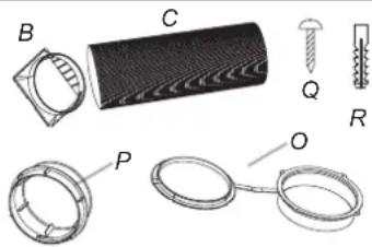
natural_image
Technical drawings of mechanical components including a cylindrical part, threaded fastener, and ring-like assemblies (no text or labels)\$□* XDUQL] LRQHOLQVFKLXP D
%JJDQFLR
&7XEROGUVFDFLFRICHVVLEUHO
* ☐ & R:OHWRUHIGLIVFDULFRISHULQDEILQHVIND
(9LGGD _2 □□□□□□
) 9LIGHJQR* 6DIIDG
FKLXVXUD[GH0:D]ILQHVIUD[□□□□]
+ [3URWH] LRQHISHUODSLRJJLD
,6H] LRQHGLVFRUUP HQIRHVHUQR
- [6H] LRQH[GL]VFRWLP HQ[MRLQ]HUQR
. 00%XORQL000
/ 00' DGL□□□
0 5 RQGH:OH:HODVILFKH
1 05 RQGHCH]SLDQH□□□□
2 □&RSHUMXUD□D□D□SDUHWH
3 LIL & ROCHWRUHIGLIVFDULFR
4 009 LWLOGL00HJQR00XQJKH000
5 7DSSLGLSODVWLFDD
text_image
Technical diagram of a mechanical assembly with labeled components A, B, C, and Dnatural_image
Simple line drawing of a container with two upward arrows and one left-pointing arrow inside (no text or symbols)
natural_image
Simple line drawing of a mechanical component with two downward arrows and a threaded base (no text or symbols)natural_image
Simple line drawing of a door with two arrows indicating left and right sides (no text or symbols)
natural_image
Simple line drawing of a door frame with two arrows pointing outward and a spring attached (no text or symbols)natural_image
Illustration of a coiled tube being handled with a transparent frame, no text or symbols presentnatural_image
Technical line drawing of a coiled pipe or duct assembly with labeled components A and B (no text or symbols beyond labels)natural_image
Illustration of a coiled tube being handled with a transparent frame, no text or symbols presenttext_image
Technical diagram of a portable air conditioner unit with labeled components A, B, C, and Dnatural_image
Illustration of a portable air conditioner unit with a coiled hose inserted, showing airflow direction (no text or symbols)natural_image
Two circular objects on a textured background, one with a diagonal line and the other empty, no text or symbols present.Copertura
USO DEL CONDIZIONATORE LOCALE
natural_image
Illustration showing two hands holding a mechanical device, with arrows indicating motion (no text or symbols)natural_image
Illustration of hands using a tool to adjust or install a component, enclosed in a circle with an arrow indicating rotation (no text or symbols present)NOTA:
NOTA: Remote control may differ in appearance.
text_image
88°C DOWN 88:88 ON/OFF MODE FAN SWING SLEEP SUPER SMART IFEEL DIMMER TIMER ON TIMER OFF CLOCKPulsanti e funzioni
| 1 | Interruttore ON/OFF | 8 | VEGLIA | |||
| 2 | MODE | 9 | IFEEL | |||
| 3 | VENTILATORE | 10 | OROLOGIO | |||
| 4 | SU | 11 | Timer Off | |||
| 5 | GIÙ | 12 | Timer On | |||
| 6 | SMART | 13 | SUPER | |||
| 7 | SWING | 14 | DIMMER |
Simboli indicatori
text_image
DOWN (Giù)NOTE:
text_image
Technical diagram of a portable air conditioner unit with labeled components A, B, C, and Dtext_image
Diagram of a portable air conditioner unit with labeled parts including a remote control and indicator lights- Parte trasera
text_image
5 7 6 8 11 9 10natural_image
Technical drawings of mechanical components including a cylindrical component, ring-like parts, and threaded fasteners (no text or labels)text_image
AN 1: A C D E F G B I H L K M N Jtext_image
Technical diagram of a mechanical component with labeled parts A, B, C, and Dnatural_image
Simple line drawing of a container with two upward arrows and one left-pointing arrow inside (no text or symbols)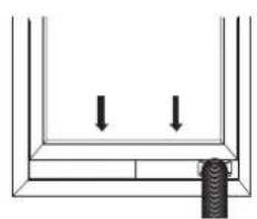
natural_image
Simple line drawing of a container with two downward arrows and a textured bottom (no text or symbols)natural_image
Simple line drawing of a door with two arrows indicating left and right sides (no text or symbols)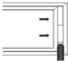
natural_image
Simple line drawing of a door frame with two arrows pointing outward and a spring attached (no text or symbols)natural_image
Illustration of a coiled tube being handled with a transparent frame, no text or symbols presentnatural_image
Technical illustration of a coiled mechanical component with labeled parts A and B (no text or symbols beyond labels)A. Manguera de escape flexible
B. Acople artificial
C. Manguera de escape flexible
natural_image
Illustration of a coiled tube wrapped in a transparent frame, with hands interacting (no text or symbols)natural_image
Illustration of a portable air conditioner unit with a hose inserted into a textured wall (no text or symbols)natural_image
Two circular objects on a textured background, one with a diagonal line and the other with a horizontal line (no text or symbols)Cobertor
USO DEL AIRE ACONDICIONADO LOCAL
natural_image
Illustration showing two hand positions: one with a device being inserted, the other holding a tool (no text or symbols present)natural_image
Illustration of hands holding a pen, with an arrow indicating direction (no text or symbols)NOTA:
- Press SUPER button. The air conditioner automatically sets the fan speed to High and the temperature to 16^ C. Fast heating operates at auto fan speed, changing the set temperature automatically to 30^ C.

- To turn off Super control, press any button on the remote control or control panel except Timer On, Timer Off, Clock, Dimmer, I feel and Swing.
NOTE:
■ In the SUPER mode you can set a airflow direction or timer.
■ SMART mode are not available in SUPER mode.
■ SUPER button is ineffective in SMART mode.
fast cooling
fast heating
Fan Speed
- Press FAN button, Choose desired fan speed.
■ Auto-Automatically controls fan speed depending on current room temperature and temperature control setting.
NOTE: Auto fan speed cannot be selected in Fan Only mode.

■ High for maximum fan speed

■ Mid for normal fan speed

■ Low for minimum fan speed

Temperatura
text_image
Technical diagram of a portable air conditioner unit with labeled components A, B, C, and Dtext_image
airbox 8 Atext_image
Diagram of a portable air conditioner unit with labeled parts including a remote control and indicator lights- Posterior

text_image
5 7 6 8 11 9 10text_image
NO 1: A C D E F G B I H L K M N JPLANO 2: (opcional)

natural_image
Technical diagram showing various mechanical components and parts (no text or labels visible)text_image
Technical diagram of a mechanical assembly with labeled components A, B, C, and Dnatural_image
Simple line drawing of a container with two downward arrows and a threaded rod at the bottom (no text or symbols)natural_image
Simple line drawing of a door with two arrows indicating left and right motion (no text or symbols)
natural_image
Simple line drawing of a door frame with two arrows pointing outward and a spring attached (no text or symbols)A. 1/2 "parafuso (fornecido 2)
natural_image
Illustration of two hands manipulating a coiled cylindrical object with a transparent frame (no text or symbols)natural_image
Technical illustration of a coiled pipe or duct assembly with labeled components A and B (no text or symbols beyond labels)natural_image
Illustration of a coiled tube being handled with a transparent frame, no text or symbols presentnatural_image
Illustration of a portable air conditioner unit with a hose inserted into a textured surface (no text or symbols)natural_image
Two circular objects on a textured background, one with a diagonal line and the other with a horizontal line (no text or symbols)Tampa
USO DO AR CONDICIONADO LOCAL
natural_image
Illustration showing two hand positions: one with a device being inserted, the other holding a tool (no text or symbols present)natural_image
Illustration of hands holding a pen with an arrow indicating direction (no text or symbols)NOTA:
text_image
Technical diagram of a portable air conditioner unit with labeled components A, B, C, and DINSTALLATIE INSTRUCTIES....12
PROBLEEMOPLOSSEN....24
VEILIGHEIDSINSTRUCTIES
text_image
Diagram of a portable air conditioner unit with labeled parts including a remote control and indicator lightstext_image
AN 1: A B C D E F G H I J K M NPLAN 2:(optioneel)
natural_image
Technical diagram showing various mechanical components and parts (no text or labels visible)INSTALLATIE INSTRUCTIES
text_image
Technical diagram of a mechanical assembly with labeled components A, B, C, and Dtext_image
Technical diagram showing a hand operating a tool with labeled parts A and B, likely illustrating a mechanical or electrical assembly.natural_image
Simple line drawing of a container with two downward arrows and a threaded rod at the bottom (no text or symbols)natural_image
Simple line drawing of a door with two arrows indicating left and right sides (no text or symbols)
natural_image
Simple line drawing of a door frame with two arrows pointing outward and a coiled spring at the bottom (no text or symbols)natural_image
Illustration of a coiled tube being handled with hands, no text or symbols presentnatural_image
Technical line drawing of a coiled pipe or duct assembly with labeled components A and B (no text or symbols beyond labels)natural_image
Illustration of a coiled tube being handled with a transparent frame, no text or symbols presenttext_image
Technical diagram of a portable air conditioner unit with labeled components A, B, C, and Dnatural_image
Diagram of a portable air conditioner unit with a hose inserted into a textured surface (no text or symbols)natural_image
Two circular objects connected by a line, placed on a textured surface (no text or symbols)Dekking
HET GEBRUIK VAN DE WANDAIRCONDITIONER
natural_image
Illustration showing two hand positions: one with a device being inserted, the other holding a tool (no text or symbols present)natural_image
Illustration of hands using a tool to adjust or install a component, enclosed in a circle with an arrow indicating rotation (no text or symbols present)OPMERKING:
text_image
Technical diagram of a portable air conditioner unit with labeled components A, B, C, and DA. Secundaire aftapplug
text_image
Diagram of a portable air conditioner unit with labeled parts including a remote control and indicator lights- Arrière
text_image
5 7 6 8 11 9 10text_image
N 1: A C D E F G B I H L K M N JPLAN 2: (optionnel)
natural_image
Technical diagram showing various mechanical components and parts (no text or labels visible)text_image
Technical diagram of a mechanical assembly with labeled components A, B, C, and Dnatural_image
Simple line drawing of a container with two upward arrows and one left-pointing arrow inside (no text or symbols)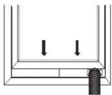
natural_image
Simple line drawing of a container with two downward arrows and a threaded base (no text or symbols)natural_image
Simple line drawing of a door with two arrows indicating left and right motion (no text or symbols)
natural_image
Simple line drawing of a door frame with two arrows pointing outward and a spring attached (no text or symbols)natural_image
Illustration of a coiled tube being handled with hands, no text or symbols presentnatural_image
Technical line drawing of a coiled pipe or duct assembly with labeled components A and B (no text or symbols beyond labels)natural_image
Illustration of a hand holding a transparent cube containing a coiled, ring-like structure (no text or symbols)text_image
Technical diagram of a device with labeled components A, B, C, and D, showing internal airflow or ventilation system.natural_image
Illustration of a portable air conditioner unit with a hose inserted, showing airflow direction (no text or symbols)natural_image
Two circular objects connected by a line, placed on a textured surface (no text or symbols)Cache
UTILISATION DU CLIMATISEUR
natural_image
Illustration showing two hand tools in a circular frame, one being inserted and the other holding a tool (no text or symbols present)natural_image
Illustration of hands using a tool to adjust or install a component, enclosed in a circle with an arrow indicating rotation (no text or symbols present)REMARQUE :
text_image
Technical diagram of a portable air conditioner unit with labeled components A, B, C, and DA. Bouchon de vidange auxiliaire
D. Couvercle principal
text_image
Diagram of a portable air conditioner unit with labeled parts including a remote control and indicator lights• Задняя сторона 5
text_image
5 7 6 8 9 10 11text_image
A C D E F G B I H L K M NПЛАН 2:(опционно)

natural_image
Technical illustration of mechanical components including a cylindrical component, ring-like parts, and screw assembly (no text or symbols)A. Монтажная пена
text_image
Technical diagram of a mechanical assembly with labeled components A, B, C, and Dnatural_image
Simple line drawing of a container with two upward arrows and one left-pointing arrow inside (no text or symbols)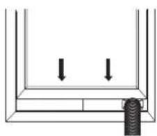
natural_image
Simple line drawing of a container with two downward arrows and a threaded base (no text or symbols)natural_image
Simple line drawing of a door with two arrows indicating left and right sides (no text or symbols)
natural_image
Simple line drawing of a door with two arrows pointing outward and a spring attached (no text or symbols)natural_image
Illustration of a coiled tube being handled with two hands (no text or symbols)natural_image
Technical illustration of a coiled pipe or duct assembly with labeled components A and B (no text or symbols beyond labels)natural_image
Illustration of a coiled tube being handled with a transparent frame, no text or symbols presenttext_image
Technical diagram of a device with labeled components A, B, C, and D, showing internal structure and airflow path.natural_image
Diagram of a portable air conditioner unit with a coiled hose inserted, showing airflow direction (no text or symbols)natural_image
Two circular objects connected by a line, one with a diagonal line and the other empty, against a textured background (no text or symbols)Крышка
natural_image
Illustration showing two hand positions: one with a device being inserted, the other holding a tool (no text or symbols present)natural_image
Illustration of hands holding a tool with an arrow indicating direction (no text or symbols)ПРИМЕЧАНИЕ:
text_image
Technical diagram of a portable air conditioner unit with labeled components A, B, C, and Dtext_image
Diagram of a portable air conditioner unit with labeled parts including a remote control and indicator lights• Die Rückseite
text_image
Technical diagram of an air conditioner unit with numbered parts labeled for identification.DISPOSING OF THE UNIT
text_image
mung 1: A C D E F G B I H L K M NPlanung 2(optional)
natural_image
Technical illustration of mechanical components including a cylindrical tube, ring, and screw (no text or symbols)A.Foam Dichtung
B.Dummy Kupplungs
D. Window Auspuffadapter
Schrauben E.1/2 "(2)
F.Wood Schrauben (4)
G. Window Blockierbügel (2)
text_image
Technical diagram of a mechanical assembly with labeled components A, B, C, and DA. Fenster Auspuffadapter
B. Regen Abdeckung
C. Austrittsgitter
natural_image
Simple line drawing of a container with two downward arrows and a threaded rod at the bottom (no text or symbols)natural_image
Simple line drawing of a door with two arrows indicating left and right sides (no text or symbols)
natural_image
Simple line drawing of a door frame with two arrows pointing outward and a spring attached (no text or symbols)E. Fenster Auspuffadapter
natural_image
Illustration of a coiled tube being handled with a transparent frame, no text or symbols presentnatural_image
Technical line drawing of a coiled pipe or duct assembly with labeled components A and B (no text or symbols beyond labels)A. Flexibler Abluftschlauch
B. Fenster-Auspuffadapter
A. Fenster Slider-Kit
B. Fenster-Auspuffadapter
natural_image
Illustration of a coiled tube being handled with a transparent frame, no text or symbols presentnatural_image
Illustration of a portable air conditioner unit with a hose inserted, showing airflow direction (no text or symbols)natural_image
Two circular objects on a textured background, one with a diagonal line and the other with a horizontal line (no text or symbols)Abdeckung