
APH09QC - Air Conditioning HISENSE - Free user manual and instructions
Find the device manual for free APH09QC HISENSE in PDF.
| Product Type | Portable air conditioner (monoblock) |
| Brand | Hisense |
| Model | APH09QC |
| Refrigerant | R290 (flammable), max charge 0.3 kg |
| Power supply | 220-240 V ~ 50 Hz, 16 A, 3-pin plug with earth |
| Cooling capacity | Not specified (model approximately 9000 BTU/h) |
| Heating capacity (heat pump) | Yes (depending on model), not specified |
| Ambient temperature range | Cooling: 21-35 °C; Heating: 7-20 °C; Drying: 19-35 °C |
| Minimum room area | 14.4 m² (for storage and use) |
| Operating modes | Cooling, Heating, Ventilation, Dehumidification, Smart, Sleep, Super, Silent |
| Fan speeds | Auto, High, Medium, Low |
| Control | Touch panel + infrared remote control (range 7 m) |
| Remote control | Yes, with AAA batteries (2 x 1.5 V) |
| Special functions | On/Off timer, Oscillation, Ifeel, Dimmer, WiFi (optional) |
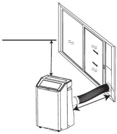
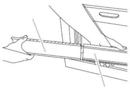
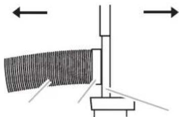
| Exhaust kit | Flexible hose (60-170 cm), window adapter, sliding kit |
| Drainage | Manual (drain pan); drain hose available in heating mode |
| Air filter | Washable, regular cleaning recommended |
| Dimensions (W x H x D) | Not specified |
| Weight | Not specified |
| Noise level | Not specified (silent mode available) |
| Included parts | Remote control, batteries, exhaust hose, window kit, seals, screws |
| Safety | Flammable refrigerant (R290), moisture protection, automatic shut-off when tank full |
| Maintenance | Filter cleaning, drainage, vertical storage before use |
Frequently Asked Questions - APH09QC HISENSE
User questions about APH09QC HISENSE
0 question about this device. Answer the ones you know or ask your own.
Ask a new question about this device
Download the instructions for your Air Conditioning in PDF format for free! Find your manual APH09QC - HISENSE and take your electronic device back in hand. On this page are published all the documents necessary for the use of your device. APH09QC by HISENSE.
USER MANUAL APH09QC HISENSE
USE AND INSTALLATION INSTRUCTIONS
APC12QB
APH12QB
APC12QC
APH12QC
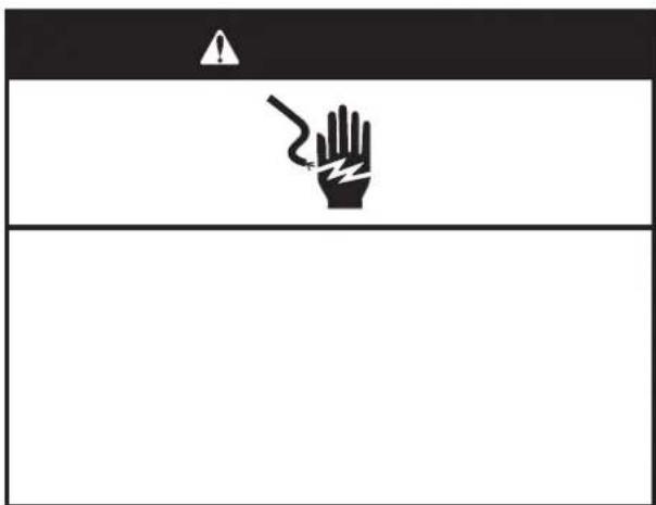
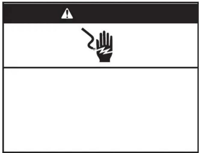
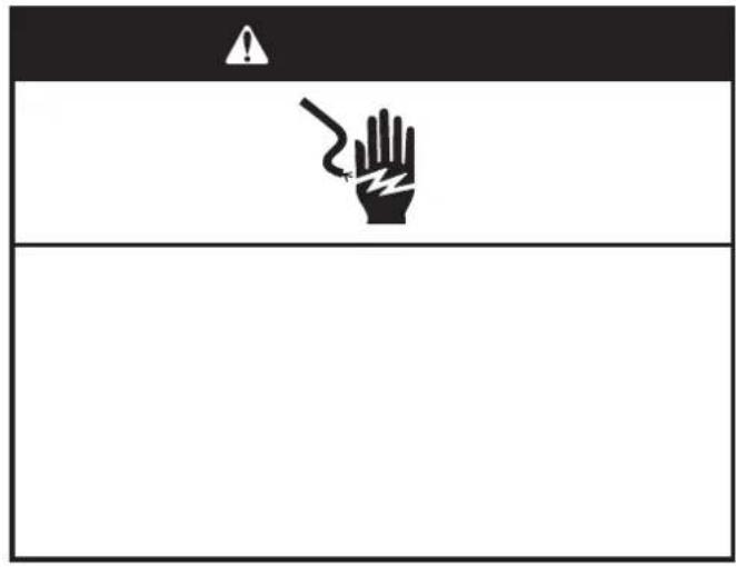
A


| Caution, risk of fire | ||
IDENTIFICATION OF PARTS
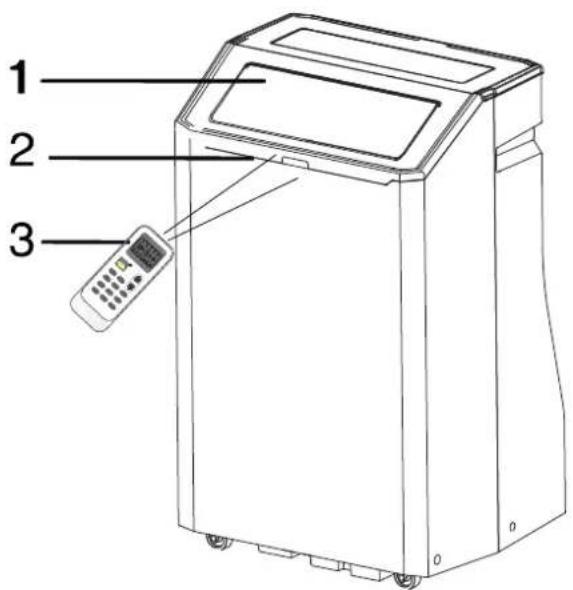
- Front
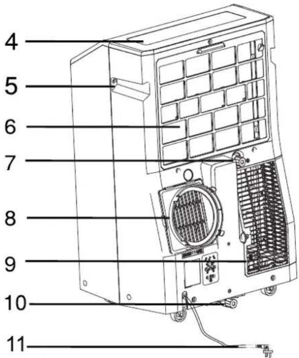
Back

Cool air outlet

Signal receptor

Remote control

Control panel

Transport handle

Evaporator air intake

Secondary drain port

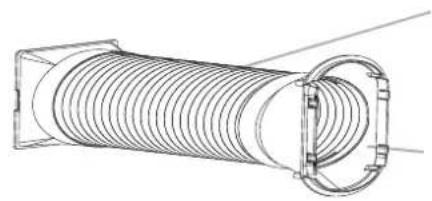
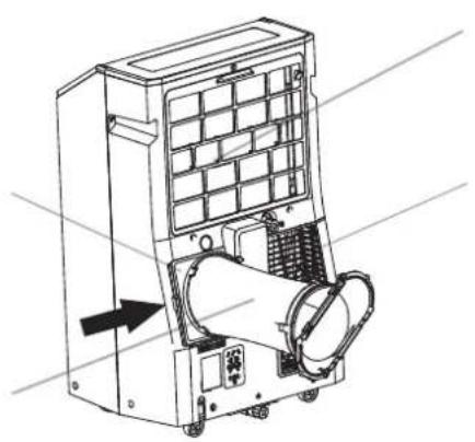
Air outlet hose coupling

Condenser air intake

Primary drain port

Power cord (May differ from the one shown)

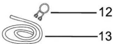
Drain hose clip (Heat pump models)

Drain hose (Heat pump models)

The figures in this manual are based on the external view of a standard model.
They may differ from that of the air conditioner you have selected.

A


■ Before throwing the device, it is necessary to pull back the battery cells and get rid of them safety for recycling reasons.
■When you need to dispose of the unit consult our dealer. If pipes are removed incorrectly, refrigerant may blow out and come into contact with your skin, causing injury. Releasing refrigerant into the atmosphere also damages the environments. please recycle or dispose of the packaging material for product in an environmentally responsible manner.
■ Never store or ship the air conditioner upside down or sideways to avoid damage to the compressor .
The appliance is not intended for use by young children or infirm persons without supervision. Young children should be supervised to ensure that they do not play with the appliance.
INSTALLATION REQUIREMENTS
Tools and Parts
Gather the required tools and parts before starting installation. Read and follow the instructions provided with any tools listed here.
Tools needed
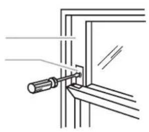
Phillips screwdriver
Scissors
Pencil
Cordless drill and 18" bit
Parts supplied
The following parts are supplied with the portable Air conditioner.
| Part | Description | Quantity |
| A. Foam seal | 1 pc | |
| B. Coupling | 1 pc | |
| C. Flexible exhaust hose | 1 pc | |
| D. Window exhaust adapter | 1 pc | |
| E. Rivets | 4 pc | |
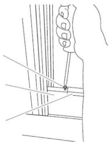
| F. Screws | 4 pc | |
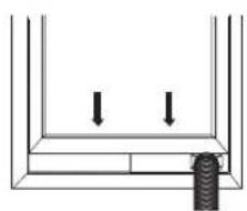
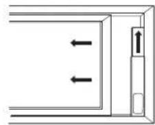
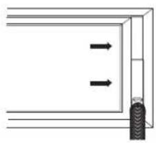
| G. Window-lock bracket | 2 pc | |
| H. Outer slider section with vent | 1 pc | |
| I. Inner slider section-short | 1 pc | |
| J. inner slider section | 1 pc | |
| K. Outer slider section | 1 pc | |
| L. Foam seal-long | 2 pc | |
| M. Foam seal-short | 2 pc | |
| N. Drain hose (Heat pump models) | 1 pc | |
| O. Drain hose clip (Heat pump models) | 1 pc | |
| P. Remote control | 1 pc | |
| Q. Standard AAA (1.5 volts) batteries | 2 pc |
Note
MERCURY FREE SUPER HEAVY DUTY R03 UM-4 SIZE AAA 1.5V BEST USED BEFORE DATE CODE (MONTH-YEAR) ON THE BOTTOM
Caution for ingestion
The battery may cause suffocation if swallowed by children
Do Not Mix Old And New Batteries. Do Not Mix Alkaline, Standard (Carbon - Zinc), Or Rechargeable (Nickel - Cadmium) Batteries
Non-rechargeable batteries are not to be recharged
Exhausted batteries are to be removed from the product
DO NOT DISPOSE OF BATTERIES IN FIRE. BATTERIES MAY EXPLODE OR LEAK.

If changing modes while the air conditioner is running,
Control panel
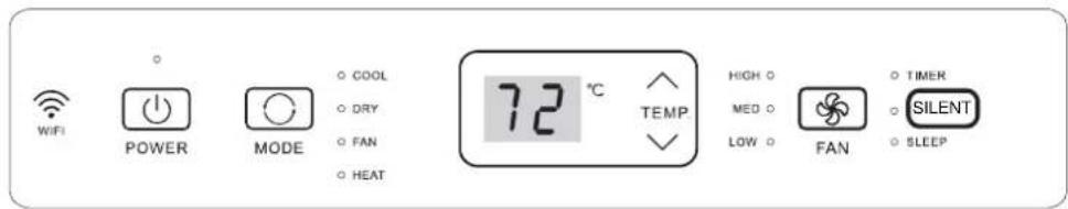
NOTE:The symbols may be different from these models, but the functions are similar.
| Power On or Off |
| ○ POWER |
NOTE: Keep upright at least 2 hours before use to prevent damaging the compressor.
At the first time when the air conditioner is plugged in and turned on after your purchase, it will be set in Cool Mode. When the air conditioner is turned on at all other times, it will run according to the previous setting.
| Mode |
- Press and release MODE until you see the symbol for the desired setting.
Operating modes:

- Choose Cool, Dry, Fan or Heat.
Cool-Cools the room. Press FAN to select High, Mid or Low speeds. Press the Plus or Minus button to adjust the temperature.

Dry-Dries the room. The air conditioner automatically selects the temperature. The fan runs on Low speed only. Dehumidification ranges between 2 to 3 pints per hour, by model.
NOTE: Dry mode should not be used to cool the room.
DRY
Fan Only mode. Press FAN to select High, Mid or Low.
FAN
Heat-heats the room. Press FAN to select high, Mid or Low speeds. Press the PLUS or MINUS button to adjust the temperature.
NOTE: Heating is NOT available for cooling only models.
HEAT (Optional)
WIFI control is available for connected models with this logo on control panel.
WiFi
WiFi (Optional)
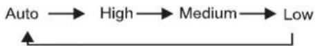
Fan Speed
- Press and release FAN to choose the desired fan speed.

- Choose High, Mid or Low.
High-for maximum fan speed
HIGH

Mid-for normal fan speed
MED

Low-for minimum fan speed
LOW
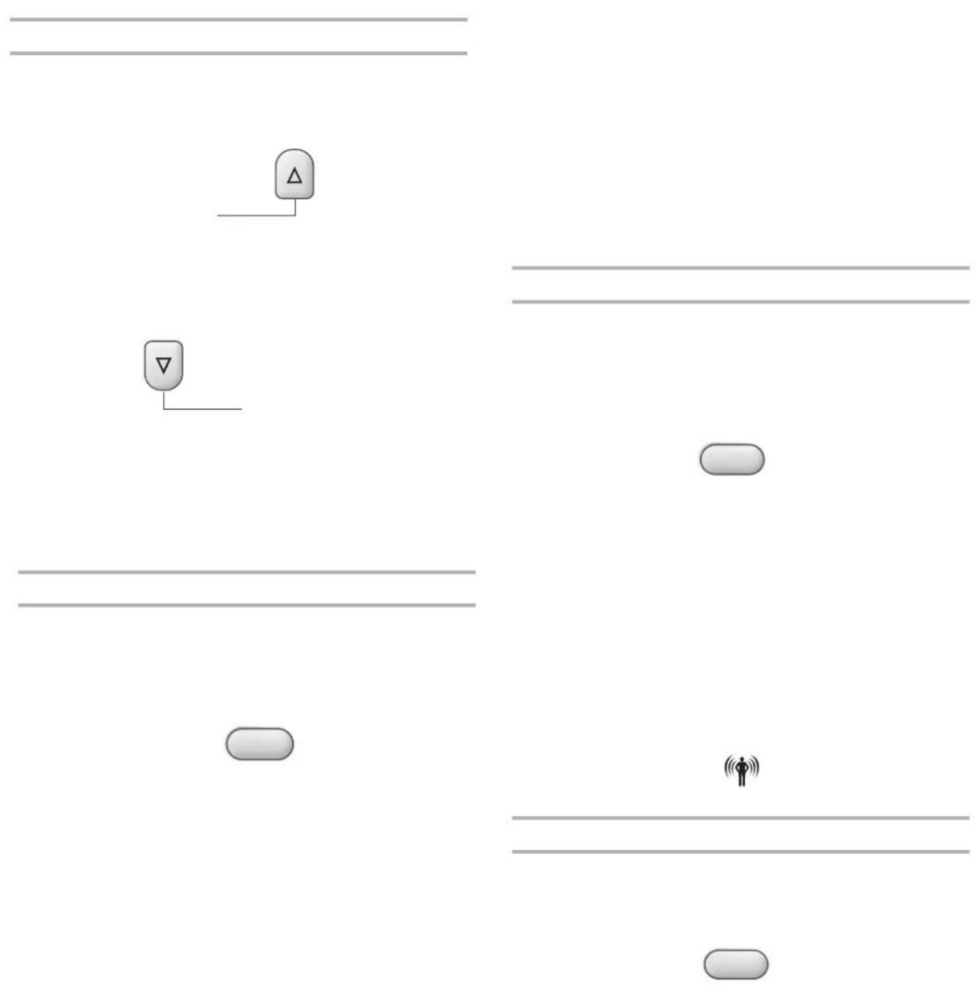
Temperature
Press the button to raise the temperature. Press the button once to increase the set temperature by 1^ ( 1^ ).

Press the button to lower the temperature. Press the button once to decrease the set temperature by 1^ ( 1^ ).

NOTE:
In the Cooling mode, the temperature can be set between 61^ and 86^ (16°C and 30°C).
In Fan Only mode, the temperature can not be set.
The unit LED shows the target temperature for 5 seconds and then displays the room temperature.
Change display between ^ F and ^ C
To change the temperature display between ^ F and ^ C press both the and Adjust buttons at the same time.
八
TEMP
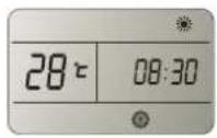
SILENT
Press the SILENTbutton to enter quiet mode.

SILENT
Using the Remote Control
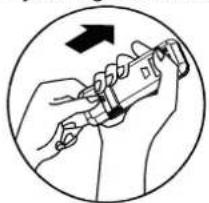
Insert the Batteries
- Remove the battery cover along the arrowed direction.
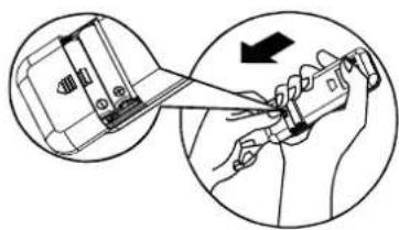
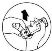
- Insert new batteries making sure that the (+) and (-) of battery are matched correctly.
- Re-attach the cover by sliding it back into position.
NOTE:
- Use 2 standard AAA(1.5volt) batteries. Do not use rechargeable batteries.
- Replace batteries with new ones of the same type when the display becomes dim, or after 6 months.
- When replacing batteries, always replace both batteries with new batteries. Do not mix old and new batteries. Do not mix alkaline, standard (carbon-zinc), or rechargeable (ni-cd, ni-mh, etc) batteries.
If the air conditioner will not be used for an extended period of time, remove the batteries from the remote.
CAUTION
- Do not use the remote if the batteries have leaked.
The chemicals in batteries could cause burns or other health hazards.
DO NOT DISPOSE OF BATTERIES IN FIRE. BATTERIES MAY EXPLODE OR LEAK.
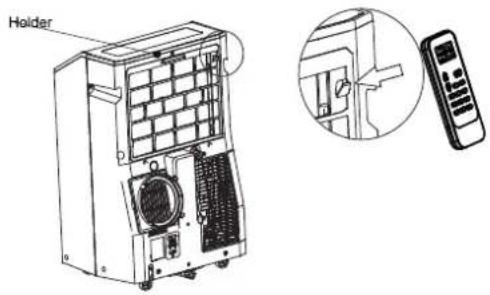
Storage Tip
The holder on the back of the unit can be used to store the remote control.
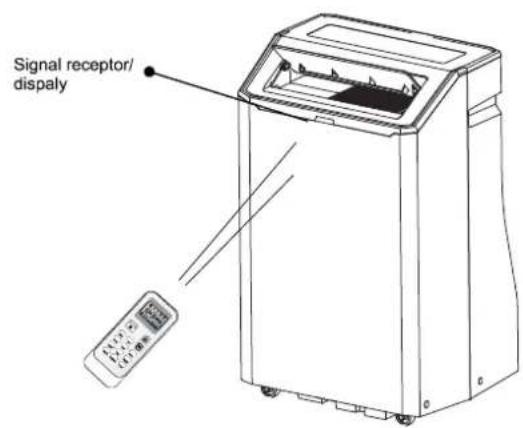
How to Use
To operate the room air conditioner, aim the remote control at the signal receptor. The remote control will operate the air conditioner at a distance of up to 23^(7m) when pointing at signal receptor of the air conditioner.

| 1 | 8 | ||||
| 2 | 9 | ||||
| 3 | 10 | ||||
| 4 | 11 | ||||
| 5 | 12 | ||||
| 6 | 13 | ||||
| 7 | 14 |
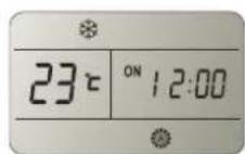
Indication symbols on LCD:
| Cooling indicator | Auto fan speed |
| Dry indicator | High fan speed |
| Fan only indicator | Medium fan speed |
| Heating indicator | Low fan speed |
| ▲ Smart indicator | Signal transmit. |
| Sleep indicator | ON OFF 88:88 Display set timer Display current time |
| Super indicator | 88℃ Display set temperature |


| Indoor temperature | Operation mode | Target temperature |
| or below | HEATING | |
| FAN ONLY | ||
| DRY | ||
| Over | COOLING |
| Indoor temperature | Operation mode | Target temperature |
| FAN ONLY | ||
| DRY | ||
| Over | COOLING |


| What you can do in mode | ||
| Your feeling | ||
| Uncomfortable because of unsuitable air flow volume. | ||
| Uncomfortable because of unsuitable flow direction. | Press it once, the louver swings to change airflow direction. Press it again, swings stops. | |


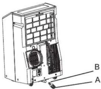
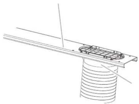
A.Primary drain cover B.Primary drain plug
WARNING
Excessive Weight Hazard
Use two or more people to move and install the air conditioner.
Failure to do so can result in back or other injury.
- Unplug the air conditioner or disconnect power.
- Move the air conditioner to a drain location or outside.
NOTE: To avoid leaking water from the unit, move the air conditioner slowly and keep it level.
- Remove the primary drain cover and plug.
-
Drain water completely through the drain hole.
-
Reinstall the drain plug to the primary drain hole.
- Reinstall the primary drain cover to the drain hole.
- Reposition the air conditioner.
- Plug in the air conditioner or reconnect power.
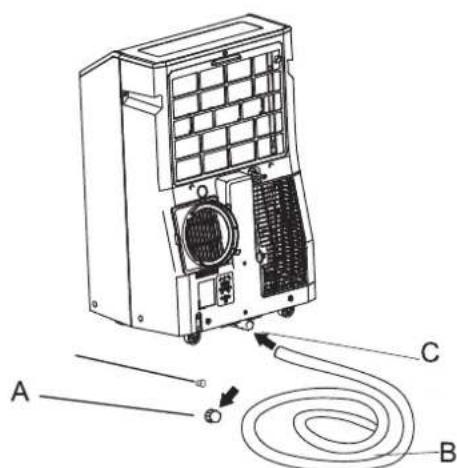
A.Primary drain port
B.Drain hose
C.Primary drain hole
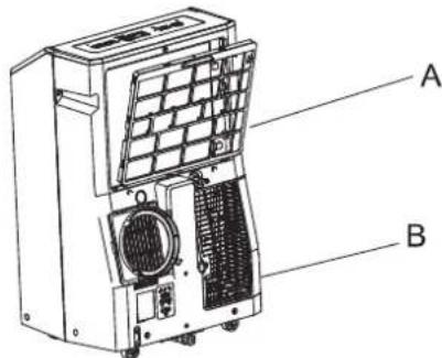
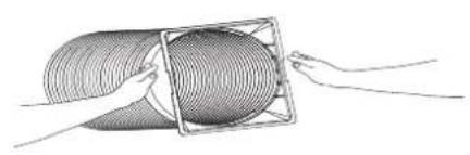
Cleaning the Air Filter
A.Evaporator air intake filter panel door B. Condenser air intake filter panel door
- Press ON/OFF to turn off the air conditioner.
- Open the filter panel door on the back of the air conditioner and remove.
- Remove the tapping screw from the condenser air intake filter panel door and remove.
-
Use a vacuum cleaner to clean the filter. If the filter is very dirty, wash the filter in warm water with a mild detergent.
-
Air dry the filter completely before replacing to ensure maximum efficiency.
- Reattach the air filter to the filter panel door.
- Reinstall the filter panel door and tapping screw
- Press ON/OFF to start the air conditioner.
Storing After Use
1.
- Run the air conditioner set to Fan Only for approximately 12 hours to dry the air conditioner.
- Unplug the air conditioner.
Hisense (Guangdong) Air Conditioning Co., Ltd.
No.8 Hisense Road, Advanced Manufacturing Jiangsha Demonstration Park, Jiangmen City, province di Guangdong, R.P.C. Cina
SOMMARIO
- Scegliere Cool, Dry, Fan o Heat.
Hisense (Guangdong) Air Conditioning Co., Ltd.
- Elija Cool, Dry, Fan o Heat.
Hisense (Guangdong) Air Conditioning Co., Ltd.
No.8 Hisense Road, Advanced Manufacturing Jiangsha
Demonstration Park, Jiangmen City, Guangdong Province, P.R. China
INDICE
PRECAUÇÖES DE SEGURANÇA 2
IDENTIFICACAO DAS PEças. 10
- Pressione TIMER ON, deposit "On 12:00" pisca no LCD.

Hisense (Guangdong) Air Conditioning Co., Ltd.

- USE AND INSTALLATION INSTRUCTIONS
- IDENTIFICATION OF PARTS
- INSTALLATION REQUIREMENTS
- Tools and Parts
- Tools needed
- Parts supplied
- Note
- Control panel
- NOTE: Keep upright at least 2 hours before use to prevent damaging the compressor.
- Fan Speed
- Temperature
- NOTE:
- Change display between ° F and ° C
- SILENT
- Using the Remote Control
- Insert the Batteries
- CAUTION
- Storage Tip
- How to Use
- WARNING
- Storing After Use
- SOMMARIO
- INDICE
Brand : HISENSE
Model : APH09QC
Category : Air Conditioning