VE 121N - Pump ESPA - Free user manual and instructions
Find the device manual for free VE 121N ESPA in PDF.
| Product type | Vertical multistage centrifugal pump |
| Brand | ESPA |
| Model | VE 121N |
| Supply voltage | 230/400 V |
| Frequency | 50 Hz |
| Rated power (P2) | 3 kW |
| Flow rate | 33 - 217 l/min |
| Head | 98 - 32 m |
| Maximum pressure | 103 mCE |
| Minimum working pressure | 32 mCE |
| Motor speed | 2800 rpm |
| Minimum efficiency index (MEI) | ≥ 0.40 |
| Liquid temperature | 4°C - 40°C |
| Ambient temperature | 0°C - 40°C |
| Storage temperature | -10°C - 50°C |
| Maximum relative humidity | 95% |
| Motor class | Class I |
| Main functions | Clean water pumping, indoor use, water supply, boosting |
| Maintenance and cleaning | No normal maintenance required; clean with a damp cloth without aggressive products; drain pipes during freezing periods |
| Safety | 30 mA residual current device recommended; mandatory grounding; never run dry |
| Spare parts and repairability | Repair only by approved technical service; consult www.espa.com |
| Disposal | No toxic materials; recycle via local collection or return to approved repairer |
| Standards and certifications | CE; 2006/42/EC, 2014/30/EU, 2014/35/EU, 2009/125/EC, 2012/19/EU, 2011/65/EU |
Frequently Asked Questions - VE 121N ESPA
User questions about VE 121N ESPA
0 question about this device. Answer the ones you know or ask your own.
Ask a new question about this device
Download the instructions for your Pump in PDF format for free! Find your manual VE 121N - ESPA and take your electronic device back in hand. On this page are published all the documents necessary for the use of your device. VE 121N by ESPA.
USER MANUAL VE 121N ESPA
natural_image
Technical line drawings of two vertical cylindrical industrial pumps with mounting flanges and internal components (no text or symbols)EN Instruction manual.... 10 (Translation from the original Spanish)
EN: EVIDENCE OF CONFORMITY
We declare, under our responsibility, that the products in this manual comply with the following directives and standards:
- Directive 2006/42/EC (Machine Security): Standard EN 809 and EN 60204-1
- Directive EMC 2014/30/EU (Electromagnetic compatibility): Standard EN 61000-6-1 y EN 61000-6-3
- Directive 2014/35/EU (Low voltage): Standard EN 60335-1 andre EN 60335-2-41
- Directive 2009/125/EC (ecological design): Regulation (EU) 2019/1781 electrical motors and variable speed drives. Standard EN 60034-30. Regulation 547/2012 for Hydraulic pumps. Standard EN 16480
- Directive 2012/19/EU (on waste electrical and electronic equipment (WEEE)): Standard EN 50419:2006 about marking of electrical and electronic equipment.
- Directive 2011/65/UE (Restriction of hazardous sustances): Standard EN 50581.
FR : DECLARATION DE CONFORMITÉ
EVIDENCE OF CONFORMITY
We declare, under our responsibility, that the products in this manual comply with the following directives and standards:
- Supply of Machinery (Safety) Regulations 2008: Standard BS 809 and BS 60204-1
- Electromagnetic Compatibility Regulations 2016: Standard BS 61000-6-1 and BS 61000-6-3.
- Electrical Equipment (Safety) Regulations 2016: Standard BS 60335-1 and BS 60335-2-41.
- The Ecodesign for Energy-Related Products and Energy Information (Amendment) (EU Exit) Regulations 2019: Standard BS 60034-30.
- The Restriction of the Use of Certain Hazardous Substances in Electrical and Electronic Equipment Regulations 2012. Standard BS 50581.
Banyoles, January 7th 2021
Josep Unyó (Technical Manager)
ESPA 2025, SL
Ctra. de Mieres, s/n – 17820 Banyoles
Girona - Spain
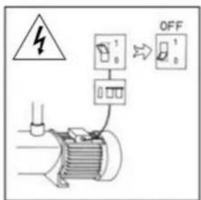
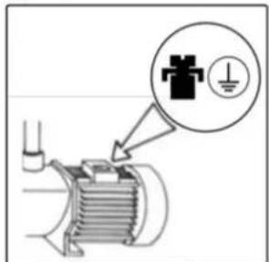
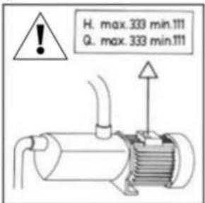
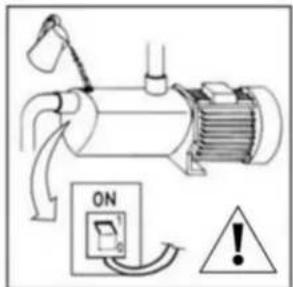
Damage prevention and safety instructions (See figure 5)
| A | Warning! Observe limitations of use. |
| B | The name plate voltage must be the same as the mains voltage. |
| C | Connect the pump to the mains via an omnipolar switch with at least a 3 mm opening between contacts. |
| D | Install a high-sensitivity differential switch (0.03A) as extra protection against lethal electric shocks. |
| E | Connect the pump to the ground. |
| F | Use pump only within performance limits indicated or the name plate. |
| G | Remember to prime pump. |
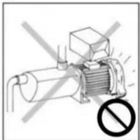
| H | Check for motor self-ventilation. |
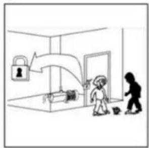
| I | This apparatus may be used by children 8 years or older and persons with reduced physical, sensory or mental capacities, or lacking experience and knowledge, if they are supervised or receive adequate training on the safe use of the apparatus and understand the dangers.Children should not be allowed to play with the apparatus.Children should not perform the ordinary cleaning and maintenance tasks without supervision. |
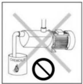
| J | Be careful with hazardous liquids and environments. |
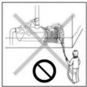
| K | Caution! Look out for accidental leaks.Do not expose pump to bad weather. |
| L | Caution! Avoid icing.Cut out power supply before servicing pump. |
Contents
Safety precautions....10
- General information....11
- Handling....11
- Installation ....11
3.1. Fixing....11
3.2. Suction pipe assembly .....11
3.3. Discharge pipe assembly 11
3.4. Electrical connection .....12
3.5. Pre-start checks 12
- Starting 12
- Maintenance 12
- Disposing of the product....12
- Nameplate 12
- Possible faults, causes and solutions....13
- Technical data 13
- List of main components....44
11.Wiring diagrams....45 - Illustrations....46
Safety precautions
This symbol
together with one of the
following words “Danger” or “Warning” indicates the risk level deriving from failure to observe the prescribed safety precautions:

DANGER
risk of
electric
shock

DANGER
Warns that failure to observe the pre cautions involves a risk of electric shock.
Warns that failure to observe the pre cautions involves a risk of damage to persons and/or things.

WARNING
Warns that failure to observe the pre cautions involves the risk of damaging the pump and/or the facility
1. GENERAL INFORMATION
Please observe the following instructions to achieve the best pump performance possible and a trouble free installation.

Read these instructions before installing the pump. Save them for future reference.
These are vertical multistage centrifugal pumps having more than one impeller assembled in-line. The same flow passes through each impeller but the pressure increases each time, i.e. more impellers, more pressure.
These pumps are designed to operate with clean water, free from particles in suspension and with a maximum temperature of 40^ C.

Correct pump operation is assured providing the instructions on electrical connection, installation and use are strictly adhered to.

Failure to adhere to the instructions can result in premature failure of the pump and voiding of the warranty.
Minimum efficiency index
With the application of the European Regulation 547/2012, the minimum efficiency index after 01/01/2015 must be MEI ≥ 0.40.
The reference value for the most efficient hydraulic pumps is rated at MEI ≥ 0.70.
The performance curves and efficiency characteristics can be checked on the technical catalogues and on www.espa.com.
The operation of this hydraulic pump with variable operating points can be cheaper and more efficient when controlled with, for example, a speed regulation control that adjusts the pump's operation to the system performance.
The efficiency reference criteria can be found on the following link:
http://global.espa.com/doc-descarrega-1/fingerprints.pdf
2. HANDLING
The pumps are supplied suitably packaged to prevent damage in transit. Before unpacking, check that the packaging has not been damaged or deformed,

Lift and handle the product with care and with the right tools.
3. INSTALLATION
These pumps are designed for indoor use. Make sure that pump is never submerged and that it rests in a dry and well aired room.
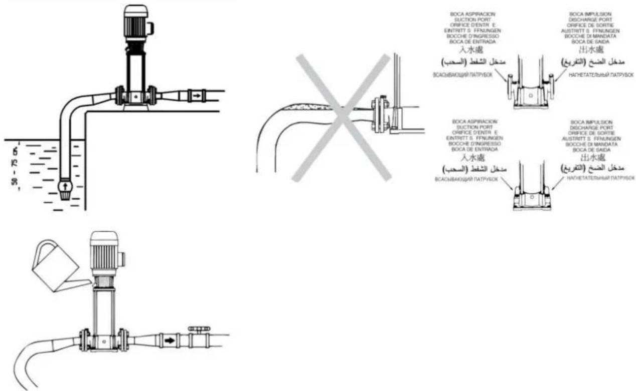
Ensure the correct hydraulic positioning with the supplied tool. (See fig.4).
3.1. Fixing
The pump should be installed on a solid, horizontal base, secured by screws or bolts and using the existing holes in the mount.
3.2. Suction pipe assembly
The suction pipe, if longer than 7 meters, must be of the same or greater diameter than the pump inlet and installed in an upward inclination to prevent trapped air pockets forming.
If the pump is required to perform a suction lift, to avoid unnecessary losses of head on the discharge side, the pump should be installed as close as possible to the water.
The end of the suction pipe must always remain, at least, 50 cm below the water level. (Fig.2)
3.3. Discharge pipe assembly
It is recommended to use pipes with a diameter equal or greater than the pump outlet. This will reduce loss of head caused by friction in longer pipe runs.
Pipework must be supported and their weight must not rest on the pump.
If a foot valve has not been installed it is recommended to fit a check valve to prevent accidental draining down of the system.
3.4. Electrical connection

The electrical installation must have a multi-pole isolator with minimum 3 mm contact openings. The protection of the system will be based on a differential switch ( fn = 30 mA )
The power cable must correspond at least to the type H05 RN-F (according to 60245 IEC 57) and having terminals.
The connection and its dimensioning must be performed by a qualified installer according to the needs of the facility and following the regulations in force in each country.

The motors are not thermally protected. They must be connected to a motor-protective circuit breaker that can be adjusted manually. Set the circuit breaker according to the current given in the rating plate plus 10%.
Follow instructions given on fig.1 for correct electrical connection.
3.5. Pre-start checks

Ensure the voltage and frequency of the supply corresponds to the values indicated on the electrical data label.
Ensure that the pump shaft is rotating freely.
Fill the pump body with water through the self-priming plug opening. If a foot valve has been installed, also fill the suction pipe.
Check all joints and connections for leaks.
THIS PUMP MUST NEVER BE DRY RUN.
4. STARTING
Ensure all valves in the pipework are open.
Connect power supply. There will be a delay before water appears at the end of the discharge pipe.
Viewings from the fan ensure that the rotation of the motor is clockwise. On three phase pumps the motor may rotate anticlockwise. If this is happening, the flow will be lower than expected. To rectify this situation the two supply phases need to be reversed.
Ensure that the absorbed current is the same or lower than the maximum shown on the nameplate.
Adjust the thermal relay if is necessary.
If the pump fails to operate refer to the possible faults, causes and solutions list for assistance.
5. MAINTENANCE
Under normal conditions these pumps require no special or planned maintenance.
Clean the pump with a damp cloth without using harsh products.

If the pump is not to be operated for a long period it is recommended to remove it from the installation, drain down and store in a dry, well ventilated place.
ATTENTION: In the event of faults or damage occurring to the pump, repairs should only be carried out by an authorised service agent.
The Official Technical Services list is in www.espa.com.
6. DISPOSING OF THE PRODUCT
When the pump is eventually disposed of, please note that it contains no toxic or polluting material. All main components are material identified to allow selective disposal.
This product or parts of it must be disposed of in an environmentally sound way, use the waste collection service. If this is not possible, contact the nearest ESPA service workshop.
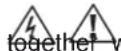
7. PLATE SHOWING CHARACTERISTICS
text_image
VE94 10 230/400 50 000093/STD 2019W14-00003 Q(l/min): 33-217 H(m): 98-32 Tmax: 40°C Hmin: 32m Hmax: 103m 2800 min.⁻¹ Motor 3kW 50Hz MEI ≥ 0,40 (η= -.) CE ESPA 2025, S.L. 17820 Banyoles (MADE IN SPAIN) Is.KL.F S1 15 9 10 11 12 13 14DESCRIPTION
| 1 | Item reference |
| 2 | Voltage + frequency + item specifications |
| 3 | Flow |
| 4 | Minimum working pressure |
| 5 | Motor max. nominal output (P2) and frequency |
| 6 | EC mark |
| 7 | Pressure |
| 8 | Maximum pressure |
| 9 | Year and week of manufacture + Pump serial number |
| 10 | Max. liquid temperature |
| 11 | Engine rotation speed |
| 12 | Minimum Efficiency Index |
| 13 | Designated motor insulation |
| 14 | Continuous operation symbol |
| 15 | Name and address of vendor responsible for the product |
8. POSSIBLE FAULTS, CAUSES AND SOLUTIONS
1) The motor does not start.
2) Motor operates but there is no pressure.
3) Motor over-heating.
4) Pump does not deliver rated capacity.
5) Motor starts and stops automatically.
6) Shaft rotates with difficulty.
| 1 | 2 | 3 | 4 | 5 | 6 | POSSIBLE PROBLEM | SOLUTIONS |
| X | X | Pump blocked | Disconnect it and take it to the official Technical Service | ||||
| X | Foot valve clogged | Clean it or replaced by new one | |||||
| X | X | Total head higher than expected | Verify geometric head and loss of head | ||||
| X | X | X | Wrong tension | Check that the tension is the same as that on the name plate | |||
| X | X | Water level in well or tank has come down | Verify suction head | ||||
| X | Fuse or thermal relay disconnected | Change fuse or thermal relay | |||||
| X | X | Impellers are worn out | Disconnect pump and take it to your Service Dealer | ||||
| X | Foot valve not submerged | Be sure suction pipe is submerged | |||||
| X | Pump was not primed | Fill pump body with water | |||||
| X | X | Room not properly aired | Provide good ventilation | ||||
| X | Air entry | Seal unions and joints properly |
9. TECHNICAL DATA
Liquid temperature: 4°C - 40°C
Ambient temperature: 0°C - 40°C
Storage temperature: -10°C - 50°C
Ambient relative humidity, max.: 95%
Motor class I.
Other data see Figure 3.
6. AFVOEREN VAN HET PRODUCT
text_image
Technical cross-sectional diagram of a mechanical device with numbered components for identification.| ES | EN | FR | DE | IT | |
| 1 | Adaptador | Adapter | Lanterne | Passfeder | Lanterna |
| 2 | Tapón de carga + aro tórico | Fill plug + OR | Bouchon de remplissage + joint torique | Füllstopfen + O-ring | Tappo di carico + OR |
| 3 | Rodete | Impeller connector | Roue | Läufer | Girante |
| 4 | Difusor | Diffuser | Diffuseur | Diffusor | Diffusore |
| 5 | Envoltura | Sleeve | Chemise | Gehäuse | Camicia |
| 6 | Cuerpo bomba | Pump body | Corps de pompe | Pumpengehäuse | Corpo pompa |
| 7 | Contrabrida + empaquetadura | Counterflange + gasket | Contre-bride + joint torique | Gegenflansche + Dichtung | Controflangia + guarnizio |
| 8 | Kit par de semijuntas | Coupling kit | Kit paire de demimanchons | Kupplungssatz | Kit coppia di semigiunti |
| 9 | Retén mecánico | Mechanical seal | Garniture mécanique | Rückhalter | Tenuta meccanica |
| 10 | Árbol | Shaft | Arbre | Welle | Albero |
| 11 | Tirante | Tie rod | Tirant | Zugstange | Tirante |
| 12 | Tapón de descarga + aro tórico | Drain plug + OR | Bouchon de vindage + joint torique | Ablassstopfen + O-ring | Tappo di scarico + OR |
| PT | NL | RU | ZH | AR | |
| 1 | Adaptador | Adapter | Кожух соединительной муфты | 適配器 | محول |
| 2 | Tampão de enchimento + OR | Vulplug + OR | Заливная пробка+O-обр. кольцо | 填寫插頭 + O型圖 | شعل قابس + یا خاتم |
| 3 | Impulsor | Waaier | Рабочее колесо | 叶轮 | المکرو |
| 4 | Difusor | Diffusor | Диффузор | 扩散器 | الناشر |
| 5 | Camisa | mouw | Гильза | 套 | ام |
| 6 | Corpo da bomba | Pomplichaam | Корпус насоса | 泵體 | جسم المنsectة |
| 7 | Contraflange + vedante | contra-flens + pakking | Ответный фланец+прокладка | 反法圖 + 垫片 | مکفحة شثة + ملوقا |
| 8 | Kit par de semi-juntas | Koppeling kit | Соединительная муфта | 偶聯試剤盒 | ahanم اقتران |
| 9 | Retentor mecânico | Mech. afdichting | Торцевое уплотнение | 机械密封 | ختم الميكانيكية |
| 10 | Veio | schacht | Вал | 軸 | رح |
| 11 | Tirante | trekstang | Шпилька | 拉桿 | ال lbadal قضيب |
| 12 | Tampão de descarga + OR | Aftapplug + OR | Сливная пробка+O-обр. кольцо | 排放塞 + O型圈 | استتراف قابس + یا خاتم |
Fig.1 / Abb.1 / Afb.1 / Puc.1 / 图 1 / 1
ALIMENTACIÓN MONOFÁSICA SINGLE PHASE SUPPLY ALIMENTATION MONOPHASÉE EINPHASENSTROM ALIMENTAZIONE MONOFASICA ALIMENTAÇÃO MONOFASICA EENFASIGE VOEDING ОДНОФАЗНОЕ ПОДКЛЮЧЕНИЕ
單相交貨
text_image
Electrical schematic symbols and component labels for a circuit or measurement device, including schematic symbols and terminal connections.Fig.2 / Abb.2 / Afb.2 / Puc.2 / 图 2 / 2
text_image
BOCA ASPIRACION SUCTION PORT ORIFICE D'ENTR E ENTRITT S. FFNUNGEN BOCCHIE D'INGRESSO BOCA DE ENTRADA 入水處 (منخل الشفط (السحب) ВСАСИВАЮЩЯ ПАТРУБОК) BOCA ASPIRACION SUCTION PORT ORIFICE D'ENTR E ENTRITT S. FFNUNGEN BOCCHIE D'INGRESSO BOCA DE ENTRADA 入水處 (منخل الشفط (السحب) ВСАСИВАЮЩЯ ПАТРУБОК) BOCA IMPULSION DISCHARGE PORT ORIFICE DE SORTIE AUSTRITT S. FFNUNGEN BOCCHIE DI MANDATA BOCA DE SAIDA 出水處 (مدخل الضخ (التاريخ) НАЧЕТАТЕЛЬНЫЙ ПАТРУБОК) BOCA IMPULSION DISCHARGE PORT ORIFICE DE SORTIE AUSTRITT S. FFNUNGEN BOCCHIE DI MANDATA BOCA DE SAIDA 出水處 (مدخل الضخ (التاريخ) НАЧЕТАТЕЛЬНЫЙ ПАТРУБОК)Fig. 3
Abb. 3
Afb. 3
Рис. 3
图3
3 الشكل
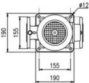
text_image
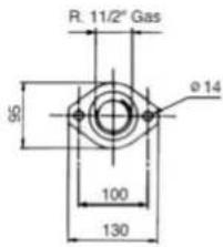
R. 11/2" Gas Ø 14 95 100 130DIN 2558 A-40
DIN 2566 C-40
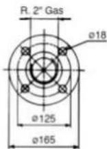
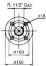
DIN 2566 C-50
VE 94
text_image
190 155 155 190 Ø12VE 121
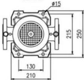
text_image
Ø15 215 250 130 210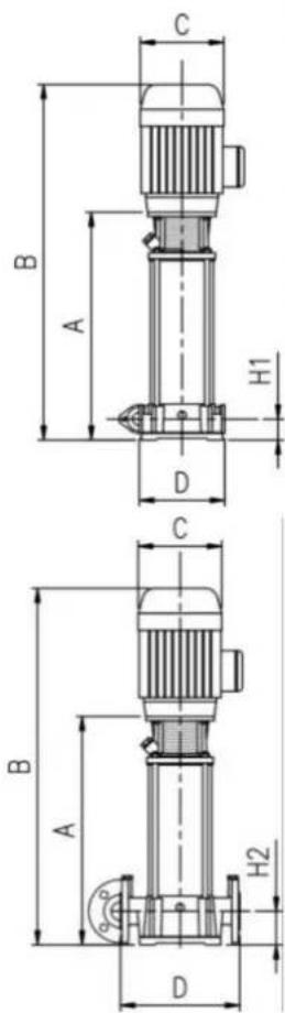
text_image
C B A H1 D C B A H2 D| 50 Hz | Q max. [l/min] | H max. [m] | P max. [MPa] | Pa max. [MPa] | A 1~220V | A 3~400V | C μF | P1 [kW] | IP | dBa ± 2 | A [mm] | B [mm] | C [mm] | D [mm] | H1 [mm] | H2 [mm] | Fig.2 | T kg |
| VE94 4 | 217 | 42 | 1,2 | 0,78 | 8,6 | 2,6 | 25 | 1,60 | 54 | 72 | 412 | 647 | 156 | 200 | 50 | - | A-40 | 33,0 |
| VE94 5 | 217 | 52 | 1,2 | 0,68 | 8,6 | 3,5 | 40 | 2,00 | 54 | 72 | 450 | 700 | 176 | 200 | 50 | - | A-40 | 35,5 |
| VE94 6 | 217 | 61 | 1,2 | 0,59 | 11 | 3,9 | 40 | 2,30 | 54 | 72 | 486 | 738 | 176 | 200 | 50 | - | A-40 | 36,5 |
| VE94 7 | 217 | 71 | 1,2 | 0,49 | - | 4,5 | - | 2,70 | 54 | 72 | 525 | 800 | 176 | 200 | 50 | - | A-40 | 45,0 |
| VE94 8 | 217 | 80 | 1,2 | 0,40 | - | 5,2 | - | 3,00 | 54 | 72 | 563 | 838 | 176 | 200 | 50 | - | A-40 | 47,0 |
| VE94 9 | 217 | 91 | 2,0 | 1,09 | - | 6,5 | - | 3,60 | 54 | 73 | 629 | 937 | 194 | 280 | - | 80 | C-40 | 60,0 |
| VE94 10 | 217 | 103 | 2,0 | 0,97 | - | 6,9 | - | 3,90 | 54 | 73 | 666 | 974 | 194 | 280 | - | 80 | C-40 | 61,0 |
| VE94 11 | 217 | 115 | 2,0 | 0,85 | - | 7,2 | - | 4,40 | 54 | 73 | 703 | 1010 | 194 | 280 | - | 80 | C-40 | 62,0 |
| VE94 12 | 217 | 122 | 2,0 | 0,78 | - | 8,3 | - | 4,80 | 54 | 74 | 742 | 1048 | 194 | 280 | - | 80 | C-40 | 65,0 |
| VE94 13 | 217 | 130 | 2,0 | 0,70 | - | 8,6 | - | 5,00 | 54 | 74 | 780 | 1086 | 194 | 280 | - | 80 | C-40 | 68,0 |
| VE94 14 | 217 | 140 | 2,0 | 0,60 | - | 9,4 | - | 5,50 | 54 | 74 | 816 | 1134 | 220 | 280 | - | 80 | C-40 | 84,0 |
| VE121 2 N | 500 | 35 | 1,2 | 0,85 | - | 6,0 | - | 3,00 | 54 | 81 | 470 | 776 | 195 | 300 | - | 90 | C-50 | 73,0 |
| VE121 3 N | 500 | 50 | 1,2 | 0,70 | - | 7,0 | - | 4,20 | 54 | 81 | 522 | 847 | 195 | 300 | - | 90 | C-50 | 80,0 |
| VE121 4 N | 500 | 66 | 1,2 | 0,54 | - | 10,1 | - | 5,50 | 54 | 81 | 574 | 943 | 220 | 300 | - | 90 | C-50 | 97,0 |
| VE121 5 N | 500 | 84 | 1,2 | 0,36 | - | 11,8 | - | 6,80 | 54 | 83 | 626 | 995 | 220 | 300 | - | 90 | C-50 | 99,0 |
| VE121 6 N | 500 | 100 | 1,2 | 0,20 | - | 14,6 | - | 7,80 | 54 | 83 | 678 | 1085 | 220 | 300 | - | 90 | C-50 | 107,0 |
| VE121 7 N | 500 | 116 | 1,2 | 0,04 | - | 16,5 | - | 9,20 | 54 | 83 | 730 | 1137 | 220 | 300 | - | 90 | C-50 | 116,0 |
| VE121 8 N | 500 | 133 | 2,0 | 0,67 | - | 19,5 | - | 10,60 | 54 | 83 | 782 | 1189 | 220 | 300 | - | 90 | C-50 | 117,0 |
| VE121 9 N | 500 | 147 | 2,0 | 0,53 | - | 21,0 | - | 13,80 | 54 | 84 | 834 | 1241 | 220 | 300 | - | 90 | C-50 | 124,0 |
| VE121 10 N | 500 | 160 | 2,0 | 0,40 | - | 23,0 | - | 15,00 | 54 | 84 | 886 | 1293 | 220 | 300 | - | 90 | C-50 | 125,0 |
| 60 Hz | Q max. [l/min] | H max. [m] | P max. [MPa] | Pa max. [MPa] | A 3~440V | P1 [kW] | IP | dBa ± 2 | A [m] | B [mm] | C [mm] | D [mm] | H1 [mm] | H2 [mm] | Fig.4 | T_ [kg] |
| VE94 5 | 240 | 74 | 1,2 | 0,46 | 5,5 | 3,3 | 54 | 72 | 450 | 726 | 176 | 200 | 50 | - | A-40 | 37,0 |
| VE94 6 | 240 | 90 | 2,0 | 1,10 | 8,1 | 4 | 54 | 72 | 517 | 821 | 164 | 280 | - | 80 | C-40 | 49,0 |
| VE94 7 | 240 | 104 | 2,0 | 0,96 | 8,1 | 4,5 | 54 | 72 | 554 | 858 | 194 | 280 | - | 80 | C-40 | 50,0 |
| VE94 8 | 240 | 120 | 2,0 | 0,80 | 9,5 | 5,4 | 54 | 72 | 591 | 895 | 194 | 280 | - | 80 | C-40 | 55,0 |
| VE94 9 | 240 | 135 | 2,0 | 0,65 | 10,3 | 5,9 | 54 | 73 | 629 | 933 | 194 | 280 | - | 80 | C-40 | 56,0 |
| VE94 10 | 240 | 150 | 2,0 | 0,50 | 13,1 | 6,9 | 54 | 73 | 666 | 994 | 218 | 280 | - | 80 | C-40 | 65,0 |
| VE94 11 | 240 | 160 | 2,0 | 0,40 | 13,1 | 7,8 | 54 | 73 | 704 | 1032 | 218 | 280 | - | 80 | C-40 | 68,5 |
| VE121 2 N | 600 | 50 | 2,0 | 1,50 | 8,0 | 4,7 | 54 | 81 | 470 | 776 | 195 | 300 | - | 90 | C-50 | 63,5 |
| VE121 3 N | 600 | 74 | 2,0 | 1,26 | 12,0 | 7,0 | 54 | 81 | 522 | 847 | 195 | 300 | - | 90 | C-50 | 69,7 |
| VE121 4 N | 600 | 100 | 2,0 | 1,00 | 17,0 | 9,5 | 54 | 81 | 574 | 943 | 220 | 300 | - | 90 | C-50 | 82,3 |
| VE121 5 N | 600 | 124 | 2,0 | 0,76 | 20,0 | 11,5 | 54 | 83 | 626 | 995 | 220 | 300 | - | 90 | C-50 | 95,0 |
| VE121 6 N | 600 | 153 | 2,0 | 0,47 | 24,0 | 14,0 | 54 | 83 | 678 | 1085 | 220 | 300 | - | 90 | C-50 | 101,0 |
| VE121 7 N | 600 | 174 | 2,0 | 0,26 | 25,0 | 17,0 | 54 | 83 | 730 | 1137 | 220 | 300 | - | 90 | C-50 | 121,0 |
text_image
Diagram showing a motor connected to an open booklet labeled ABC, with a person icon and directional arrow indicating rotation or transformation.A
text_image
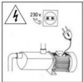
230 V F 230 VB
text_image
Diagram showing electrical hazard symbol and circuit components with labels 'OFF' and warning symbolsC

text_image
Diagram showing electrical hazard symbol and circuit components with labeled switches and indicatorsD
text_image
Diagram showing a motor with a warning symbol and electrical symbols, indicating a hazard or hazard.E
text_image
H. max. 333 min.111 Q. max. 333 min.111F
text_image
Diagram showing electrical circuit components with ON/OFF warning symbol and warning triangleG
natural_image
Diagram of an electric motor with a crossed-out valve and no visible text or symbolsH
natural_image
Simple line drawing of a room with a person walking and a person standing near a door, featuring a lock and wall-mounted device (no text or symbols)I
text_image
CHEMICAL NO]
text_image
Safety warning illustration showing a person disinfecting an industrial pipe with a 'No' symbol belowK
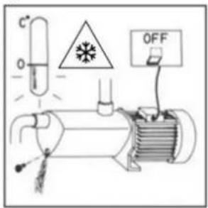
text_image
Diagram of an electrical circuit with labeled components including a test tube, warning symbol, and OFF buttonL
ESPA 2025, S.L.
C/ Mieres, s/n - 17820 BANYOLES
GIRONA - SPAIN
www.espa.com