Super Bassman - Guitar amp FENDER - Free user manual and instructions
Find the device manual for free Super Bassman FENDER in PDF.

| Product type | Tube bass amplifier head |
| Brand | Fender |
| Model | Super Bassman |
| Output power | 300 W RMS at 8 Ω, 4 Ω or 2 Ω (THD < 5%) |
| Power consumption | 900 W |
| Power supply | 100–240 V AC, 50/60 Hz depending on version |
| Channels | 2 (Vintage and Overdrive) with footswitch selection |
| Vintage EQ | Passive Bass, Passive Mid, Passive Treble + Deep/Bright (Pull) |
| Overdrive EQ | Bass ±15 dB, Mid Frequency sweep 200 Hz–3.3 kHz ±18 dB, Treble ±15 dB |
| Power tubes | 6 × 6550C |
| Preamp tubes | 3 × 12AX7A, 1 × 12AT7 |
| Automatic bias | Yes (Fender Automatic Bias) with WARM/NORMAL/COOL setting |
| Speaker outputs | Main Speaker + Extension, impedance switch 2/4/8 Ω |
| XLR output | Yes, line level, pre/post with Ground Lift |
| Effects loop | Yes (PREAMP OUT / POWER AMP IN) at line level |
| Tuner output | Yes (TUNER OUT) |
| Instrument inputs | 2 (input 1 high sensitivity, input 2 at -6 dB) |
| Footswitch included | Yes, for channel switching |
| Dimensions (H × W × D) | 25.4 × 62.2 × 34.3 cm |
| Weight | 29.5 kg |
| Main fuse | F 10 A L (125 V) or F 5 A L (250 V) depending on version |
| Power fuses | 3 × T100 mA L (250 V) |
| Maintenance | Clean with a dry cloth. Replace worn-out tubes. Have any complex repairs done by an authorized service center. |
Frequently Asked Questions - Super Bassman FENDER
User questions about Super Bassman FENDER
0 question about this device. Answer the ones you know or ask your own.
Ask a new question about this device
Download the instructions for your Guitar amp in PDF format for free! Find your manual Super Bassman - FENDER and take your electronic device back in hand. On this page are published all the documents necessary for the use of your device. Super Bassman by FENDER.
USER MANUAL Super Bassman FENDER
MANUAL DE INSTRUÇÕES
操作方法
Fender® www.fender.com
Super Bassman®
Thank you for choosing the Fender® Super Bassman 300 watt tube bass head. This amplifier was designed to provide the ultimate bass playing experience, with two channels (Vintage/Overdrive), classic good looks and modern technology designed to maximize classic technology.
The Vintage channel offers a classic Fender passive tone stack. This "cut-only" interactive circuit provides a distinctly old-school caramel-like thickness to the notes. The Overdrive channel has an active tone stack, very quick and responsive, with the ability to get incredibly
aggressive. Foot switch between these on stage for an instant tone make-over.
Fender Automatic Bias removes "tube anxiety" by constantly monitoring and re-biasing the tubes for perfect performance and alerting when service is required. Silent recording is easy. Simply turn the Speaker Output switch to MUTE and capture the preamp tone out of the XLR output without waking the neighbors!
The Super Bassman will provide a life time of thick, natural, balanced tone that sits fat in your live or studio mix.
Front Panel
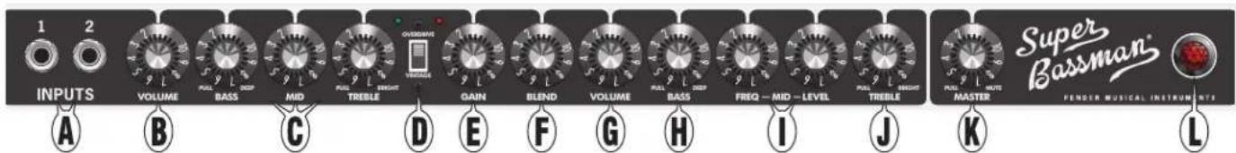
A. INPUTS: Plug your bass into the input that sounds the best to you. Input 2 is a lower sensitivity input (-6dB) and provides cleaner response with high-output or active instruments. If both inputs are used simultaneously, their input sensitivities become identical, both -6dB.
B. VOLUME: Adjusts the volume level of the Vintage channel.
C. BASS/MID/TREBLE: Classic, cut-only (passive) tone stack. Pull the BASS knob out for emphasis in the low-frequency range (DEEP). Pull the TREBLE knob out for an increase in the high-frequency range (BRIGHT).
D. CHANNEL SELECT: Selects the active channel as indicated by the green and red LEDs. When the VINTAGE channel is selected (switch in the down position, green LED), the knobs on the left (B–C) are active. When the OVERDRIVE channel is selected (switch in the up position, red LED), the knobs on the right (E–J) are active.

The included Footswitch can also be used to select channels. See FOOTSWITCH (U) on next page.
E. GAIN: Adjusts the amount of preamp tube distortion in the Overdrive channel.
F. BLEND: Controls the amount of distorted signal (set by GAIN) to be blended with the clean bass signal. Lower settings can maintain a cleaner tone, with some added grit. Higher settings will produce more distorted tones and add sustain. Set to "1" for clean tube bass signal only.
G. VOLUME: Adjusts the volume level of the Overdrive channel. Use together with the GAIN knob (E) to set the overall loudness of the Overdrive channel.
H. BASS: Adjusts the amount of low-frequency boost or cut ( ± 15dB) of the Overdrive channel. Set this knob to the center detent position for flat bass response. Pull this knob out for low-frequency emphasis (DEEP).
I. MID FREQ/MID LEVEL: Use the FREQ knob to set the frequency at which the LEVEL knob adjusts the middle-frequency boost or cut (±18dB) of the Overdrive channel. Set the LEVEL knob to the center detent position for flat mid response.

It is easiest to adjust MID when the LEVEL control is at its maximum or minimum, so that the effect of the FREQ knob is more easily heard. Once the proper FREQ setting is found, adjust the LEVEL knob to the desired setting.
J. TREBLE: Adjusts the amount of high-frequency boost or cut (±15dB) of the Overdrive channel. Set this knob to the center detent position for flat treble response. Pull this knob out for a high-frequency boost (BRIGHT).
K. MASTER: Adjusts the overall volume of the amplifier. Pull this knob out to mute all outputs from the amp except the TUNER output, useful for silent instrument tuning.
L. POWER INDICATOR: Illuminates when power to the unit is switched on.
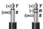
TRS Connections
NOTE: The TUNER OUT (V), POWER AMP IN and PRE AMP OUT (W) jacks are balanced TRS (Tip/Ring/Sleeve) type jacks, with tip=positive (+), ring=negative (-) and sleeve=ground (GND). While standard shielded TS (Tip/Sleeve) "mono" guitar cables can certainly be used, the use of "stereo" TRS cables may improve signal-to-noise ratio and reduce hum due to line noise.
Rear Panel
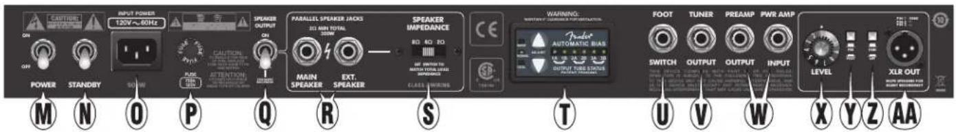
M. POWER SWITCH: Switches power on-off to the unit. Both the POWER switch and the STANDBY {N} switch must be in the "ON" position to play the amplifier. Switch to the "OFF" position to completely shut off power to the amplifier.

You can extend the life span of the amplifier tubes by keeping the Standby switch in the "STANDBY" position for the first 60 seconds each time you switch the Power to "ON."
N. STANDBY SWITCH: In the "STANDBY" position, high-voltage power is turned off to the pre-amp and power-amp tubes, extending their life and silencing the amplifier. Power is still supplied to the tube filaments, keeping them warm and ready.

Use STANDBY instead of switching the POWER off during short breaks to extend tube life span and to avoid the tube warm-up delay upon returning to play the amp.
O. POWER INLET: Connect to a grounded outlet in accordance with the INPUT POWER voltage and frequency specified above the power socket on your amplifier.
P. PRIMARY/MAINS FUSE: Protects the amplifier from electrical faults. Replace a blown fuse only with the type and rating specified below the fuse holder on your amplifier.
Q. SPEAKER OUTPUT SWITCH: Select the MUTE position if you want to disable the MAIN and EXTENSION speaker outputs (R) but not the XLR OUT (AA) output. This allows for "silent" recording by keeping the preamp active, while protecting the power amp if the speaker is disconnected, and to reduce wear on the power amp tubes.
R. MAIN SPEAKER/EXTENSION SPEAKER: Connect speaker enclosures, then set the SPEAKER IMPEDANCE switch (S) accordingly.

A speaker must ALWAYS be connected to the MAIN SPEAKER jack when the amplifier is ON or damage may occur to the unit. Switch the amplifier to STANDBY (N) or switch SPEAKER OUTPUT (Q) to MUTE while changing speaker connections.
S. SPEAKER IMPEDANCE: Set this switch to match the total load impedance of the speakers you have connected, according to the table below:
| MAIN SPEAKER | EXTENSION SPEAKER | TOTAL IMPEDANCE | IMPEDANCE SWITCH SETTING | |
| 8Ω | + | None | = 8Ω | 8Ω |
| 8Ω | + | 8Ω | = 4Ω | 4Ω |
| 4Ω | + | 8Ω | = 2.6Ω | 4Ω |
| 4Ω | + | None | = 4Ω | 4Ω |
| 4Ω | + | 4Ω | = 2Ω | 2Ω |
| 2Ω | + | None | = 2Ω | 2Ω |

Switch the amplifier to STANDBY (N) or switch SPEAKER OUTPUT (Q) to MUTE while changing SPEAKER IMPEDANCE settings.
T. AUTOMATIC BIAS: Monitors and adjusts the bias setting for your amplifier's power output tubes. Please refer to the Fender Automatic Bias section on the next page for greater detail.
U. FOOTSWITCH: Plug the included footswitch in here to enable remote channel switching. When the footswitch is connected, the front panel CHANNEL SELECT switch (D) is disabled, but the channel indicator LEDs will operate normally.
V. TUNER: Connect your instrument tuner here.
W. PREAMP OUT/POWER AMP IN: Multi-functional input/output jacks that can be used in a variety of configurations:
- Effects loop: Connect PREAMP OUTPUT to the input of your effects device and connect PWR AMP INPUT to the output jack of your effects device. The signal level here is nominally line level (+4dBu) and is most suitable for professional rack-style effects. MASTER (K) affects the send level, and the effects device controls the return level.
- Multiple Super Bassman amps: Connect PREAMP OUTPUT on the primary unit to POWER AMP IN on an auxiliary unit. The knobs on the primary unit control the auxiliary unit.
X. LEVEL: Use to adjust the output level of the XLR OUT jack (AA) to accommodate the input sensitivities of outboard sound equipment.
Y. PRE/POST: Select "POST" to include all preamp adjustments (B-C or E-J) in the XLR OUT signal. Select "PRE" for a DIRECT tube driven signal, unaffected by preamp controls.
Z. GROUND/LIFT: Select "LIFT" to disconnect the ground connection on the XLR OUT jack which may reduce hum or line noise in some situations. Normally leave this button out, in the "GND" (grounded) position.
AA. XLR OUT: A balanced, line level output for connection to mixing consoles and recording equipment. Set the SPEAKER OUTPUT switch (Q) to "MUTE" for silent recording.
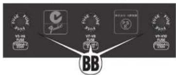
BB. POWER TUBE SCREEN FUSES: These fuses protect the amplifier from tube failures in the respective pair of power
tubes. Replace a blown fuse only with the type and rating specified below the fuse holder on your amplifier.
Fender Automatic Bias
Many musicians desire the rich and full tones produced by a tube amplifier, but heavy amps full of glass tubes which must be maintained and occasionally serviced can be intimidating. The goal of Automatic Bias is to maximize tube life and ensure peak performance.

Bias: What is it? Why is it Important?
The bias setting on your tube power amplifier determines the idle current flowing through each tube. In other words, the bias setting (WARM/NORMAL/COOL), determines how much power is flowing through each tube at idle (while the amplifier is not being played).
Tubes are complex devices that are difficult to manufacture in a consistent way. To account for this, tubes are often measured and then given "grades" to sort them by performance characteristics. All tubes of the same grade can be set at the same bias, which is why in traditional tube amplifiers (without Fender Automatic Bias) it is necessary to replace all output tubes at the same time and with a matched set of the same grade. Furthermore, if the new matched set is not the same grade as the old matched set the amplifier would need to be taken to a service center to have the bias adjusted.
Fender Automatic Bias monitors the bias of each tube individually. If one tube fails, it is not necessary to replace all output tubes with a matched set. Simply replace the single failed tube with a tube of the same type and grade. When it is necessary or desired to replace all six (6550C) output tubes at the same time, a matched set (of six tubes) of any grade may be used.
The bias setting affects amplifier tone, dynamics, tube life, and power consumption in the following ways:
WARM: More aggressive (dirtier) tone, faster attack. Shorter tube life, higher power consumption.
NORMAL: Typical setting. Good balance between tone and tube life.
COOL: Less aggressive (cleaner) tone, smoother attack. Longer tube life, lower power consumption.
Adjusting the Tube Bias
Press the up/down ADJUST buttons for WARM/COOL settings. Each button may be pressed 5 times from the NORMAL setting for the full range of bias adjustment. The range of bias (per tube) is 23mA (COOL) to 28mA (NORMAL) to 33mA (WARM). The amplifier does not need to be in standby for this adjustment. Allow 10-20 seconds for the adjustment to be completed. The LEDs will stop blinking when the adjustment is complete.
NOTE: To preserve the amplifier's rich tube tone, Fender Automatic Bias will not make any bias adjustments while the amplifier is being played. Fender Automatic Bias will always wait until the amplifier is at idle or being played at very low levels before making any adjustments.
Press and hold both the up and down arrows to restore the bias to factory settings (NORMAL). Always restore the bias settings to factory setting after installing an entire set of new tubes with a different grade than the previous set.
Output Tube Status LED Indicators
Fender Automatic Bias has one LED indicator for each output tube, corresponding to the location of each output tube from left to right on the back of the amplifier. These LEDs show the current status of the output tubes and can aid in service and trouble-shooting. Here is a definition of each of the LED display functions:
| GREEN LED moving left to right | The tubes are warming up. You should always wait longer than one minute before taking the amplifier out of STANDBY. The SPEAKER OUTPUT switch must be ON or the amplifier will remain in the warmup state.NOTE: If the STANDBY switch is set to ON before one minute (not recommended), the display will not update until after the one minute warm up period has passed. |
| LED is solid green | The tube is OK and operating at the desired bias level (WARM/NORMAL/COOL). |
| LED is green and blinking | The bias for that tube is being adjusted. It can take up to 20 seconds to complete the adjustment.NOTE: If an LED blinks continuously for longer than 5 minutes (after power-up or bias adjustments), that tube is worn out and should be replaced. |
| LED is orange | The tube is wearing out and should be replaced with a new tube with the same tube rating. |
| Within any pair (1A/1B, 2A/2B, 3A/3B) one LED is red and the other LED is orange | The tube indicated with the red LED has failed, and should be replaced (refer to the Tube Replacement section on next page for instructions). The tube indicated with the orange LED, has been shut off to allow the amplifier to run safely with the remaining pair(s) of tubes (green LEDs).NOTE: In this condition the amplifier will continue to operate safely (and allow you to finish your gig), but will operate with only the remaining power tubes at reduced power. |
| Within any pair (1A/1B, 2A/2B, 3A/3B) both LEDs are red | Sometimes, if a tube fails under certain high level signal conditions, Fender Automatic Bias cannot determine which tube of the pair has failed, and displays both in the pair red. It is still safe to operate the amplifier in this mode, but it will operate at reduced power (as discussed above).There are two service options in this situation (refer to the Tube Replacement section for tube replacement procedure):1. Replace both tubes that were indicated red, and the appropriate fuse (BB).OR2. Troubleshoot to replace only the failed tube. This is the best option if replacing both tubes is not practical (i.e., at a gig), and spare fuses are available.A. Replace either of the tubes that were indicated red, with a new or known good tube. Keep the removed tube handy, in case it was not actually the failed tube.B. Replace the appropriate tube fuse (BB) with the same type and rating.C. Turn POWER (M) on, keep the amplifier in STANDBY (N) at least one minute.D. Take the amplifier out of STANDBY, wait 10-15 seconds for Fender Automatic Bias to determine the tube status and update the display.E. If all LEDs are now green, the bad tube was replaced (dispose of the removed tube properly).F. If the two LEDs remain red, the wrong tube was replaced. Keep the removed tube and proceed to step G.G. Remove the other tube in the pair with the red LED indicator and replace it with the tube that was removed during step A. Repeat steps B-E.H. If there are still two red LEDs, both tubes had failed. Replace the tube from step g with a brand-new tube (dispose of the removed tube properly). Repeat steps B-E. |
| All LEDs are red or orange | Multiple tube failures; the amplifier will be silent. Service each pair of tubes as described above. This is unlikely to occur.NOTE: If any tubes are missing (not installed), the LED indicator for that tube will display orange. A pair of tubes may also display orange if the fuse for that pair of tubes is missing and Fender Automatic Bias did not detect a tube failure. |
| All LEDs flash at a slow rate | The amplifier has been placed in STANDBY (N) or the SPEAKER OUTPUT switch (Q) has been set to MUTE. |
Tube Replacement
The Super Bassman uses the following types of tubes:
Pre-Amplifier: Two 12AX7A tubes (V1, V2)

(Upper Chassis, bottom view)
Power Amplifier: One 12AX7A tube (V3), One 12AT7 tube (V4), and Six 6550C power tubes (V5, V6, V7, V8, V9 and V10)
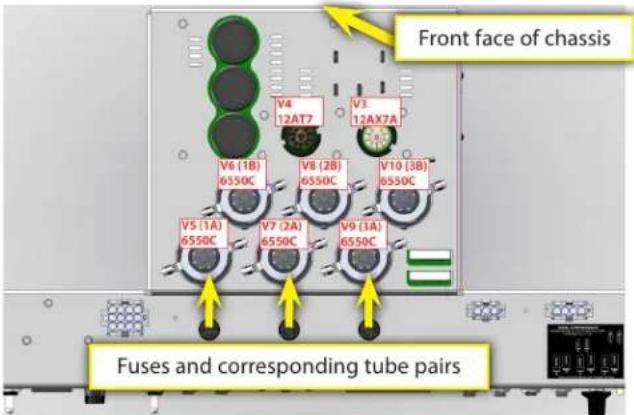
(Lower Chassis, top view)
If your amplifier is not performing as it should, refer to the Troubleshooting section below. Generally speaking with most tube audio amplifiers the tubes are the most likely thing to fail and may be replaced without taking your amplifier to a qualified service technician. If any tubes need replacing, carefully read and follow these steps. If you do not feel comfortable replacing your amplifier's tubes, take it to an authorized Fender service center. All other service needs should be referred to an authorized Fender service center. There are no user serviceable parts inside the electronics chassis. Lethal voltages exist inside your tube amplifier. Tube amplifier components get very hot. Failure to follow all these instructions may result in damage to your amplifier, or personal injury.
How to Replace the Tubes on Your Amplifier
- If Fender Automatic Bias indicated a tube failure, make a note of which tube(s) failed. NOTE: Bad tubes will remain displayed as bad until they are replaced, even if the power is cycled on/off.
- Turn off the amplifier and remove the power cable from the IEC inlet (O). You might also want to disconnect other cables (such as the speaker, line-out, effects loop, etc) so that they are not in the way.
- Caution: Tubes and transformers get very hot during operation, and may cause burn injuries. Wait for the amplifier to cool down before proceeding to step 4.
-
After the amplifier has cooled down, to gain access to the preamp tubes use a #2 Phillips screw driver to remove the 4 nickel screws holding the front grille underneath the front panel controls. Power amp tubes can be accessed by using a Phillips screwdriver to remove the 5 black screws holding the rear metal grille. Remove the grille slowly and disconnect the connector for the FAN wires.
-
You now have access to all of the tubes. Preamp tubes have metal shields that must be twisted and pulled down to remove them. Pull the tubes straight down to remove them. The small driver tubes near the power tubes have no shields and may simply be pulled straight up to remove them. The power tubes each have a top retainer ring (and insulating washer) held down by springs. Gently lift each retainer up pull it over the tube and off to the side. Pull the tubes straight upward to remove them and avoid rocking them side-to-side to prevent breakage. They should be somewhat difficult to remove. Caution: Excessive side-to-side motion could cause the locator pin on the bottom of the tube to fracture in the socket, which will not be covered by the Fender Electronic Product Warranty to remove. If you are uncomfortable in performing this process please seek the assistance of an Authorized Fender Electronics Service Center.
- Refer to the tube chart for tube type and location. Fuse holders are marked to indicate the corresponding tube pairs.
- Replace faulty tubes with tubes of the same type. Refer to the note below about proper tube handling methods. Any output tube should be replaced with the same type (6550C) and grade.
- Replace all the necessary fuses. NOTE: The type of fuses used for the tubes can be blown without showing any visible signs of failure. If Fender Automatic Bias indicated that one or more tubes have failed, you should replace the fuse for the corresponding pair(s) of tubes, even if it looks okay.
- Replace the front grille and install the four nickel mounting screws if necessary. Replace the rear metal grille and install the five black mounting screws. Don't forget to reconnect the FAN wires before installing the rear metal grille.
- Reconnect the speaker cable and any other signal cables you disconnected in step 2.
- Reconnect the power cable.
- Turn on the amplifier, but keep it in standby for at least 1 minute.
- Press and hold the up/down adjust buttons for 2 seconds to reset the Automatic Bias settings.
- Take the amplifier out of standby and wait for the Fender Automatic Bias display to update (10-15 seconds). If the display still indicates that the tubes are bad, either the fuse or tubes used as replacements were not good. Repeat steps 1-14, with new tubes or fuses.
Note on Handling Tubes
It is important not to leave fingerprints, grease, or other foreign substances on the glass surface of the tubes. This is especially important for the power output tubes. If fingerprints or other substances are left on the surface of the tube, they will cause the tube to become hotter than normal in that spot, which can lead to cracks in the glass and premature failure of the tube. Some people recommend not touching the tubes with bare hands at all. However, it this is usually impossible to avoid. Take the following steps to ensure that the tubes are clean and will have the maximum possible life:
- Wash your hands before handling the tubes.
- Avoid excess handling of the tubes.
- After installation of the tubes, wipe them with a clean cloth to remove any fingerprints or foreign substances.
Troubleshooting

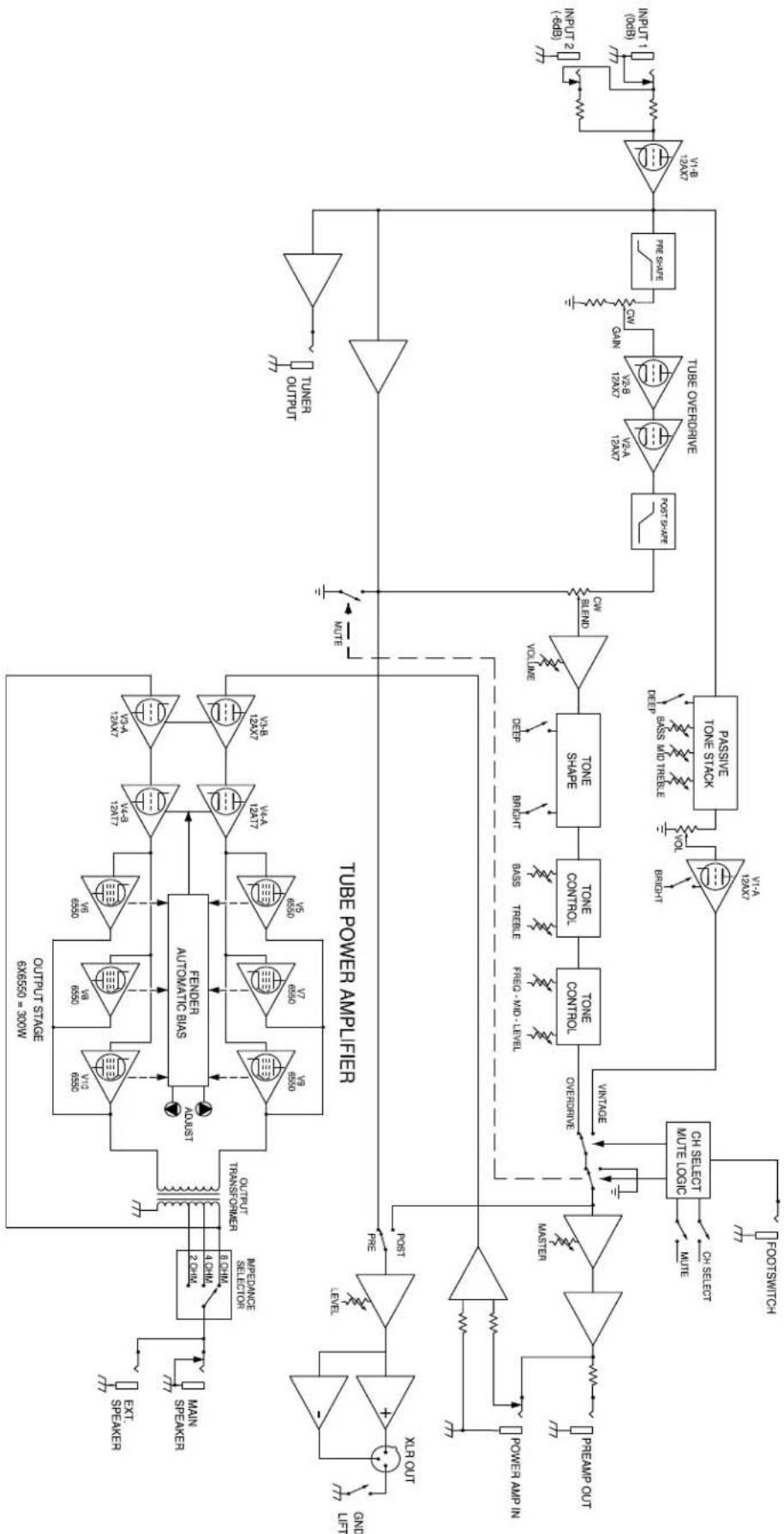
Please see the block diagram of the Super Bassman amplifier circuitry on page 6 for reference.
PROBLEM: I cannot hear any sound coming out of my Super Bassman, but my instrument is plugged in and the power to the amplifier is turned on and the red jewel (L) on the front is glowing.
SOLUTIONS:
- Make sure the VOLUME knobs (B and G) and MASTER Volume (K) are set above 1.
- Make sure that the MASTER Volume knob (K) is pressed in (defeat "MUTE").
- Make sure the STANDBY switch (N) is in the up position.
- Check the position of switch (Q).
- If outboard gear is connected in the effects loop (W) (between PREAMP OUTPUT and PWR AMP INPUT) make sure it is turned on and functioning. If unplugging the cable from the PWR AMP INPUT jack solves the problem, the problem is in the outboard gear in the effect loop, not with the Super Bassman.
- Check the status of the OUTPUT tubes on the Automatic Bias panel (T). If there are problems with the output tubes, refer to the 'Fender Automatic Bias' section for further instructions troubleshooting tubes.
- Verify that the speaker cable is connected properly between the MAIN SPEAKER jack (R) and the speaker cabinet.
- Try replacing the speaker and instrument cables.
- Try a different instrument.
If none of these solutions solve the problem, investigate the pre-amp tubes (see below).
PROBLEM: No sound is coming from the amplifier when the instrument is connected to INPUT (A), but the amplifier DOES work when connecting the instrument directly into the POWER AMP INPUT (W).
SOLUTIONS: One of the preamp tubes V1 or V2 (both 12AX7) is bad. If the amplifier works normally in the VINTAGE channel, but does not work properly in the OVERDRIVE channel (unless BLEND (F) is set to 1), replace preamp tube V2 with a new tube. Otherwise, replace preamp tube V1 with a new tube.
PROBLEM: Amplifier feeds back creating a loud high-pitched sound, even when no instrument is connected, and especially when Volume, Gain, or tone controls are at high settings in either channel. Or the amplifier creates unintentional ringing noises, which sound like chimes, while playing certain notes. Or mechanical noises like tapping on the amplifier chassis (i.e., with a pick or drumstick) are picked up and amplified through the speakers.
SOLUTIONS: Preamp tubes are becoming microphonic. Replace V1 and/or V2 (both 12AX7) with a new tube. If the problem only occurs in the OVERDRIVE channel, try replacing V2 first.
PROBLEM: Signals are present and working normally in the PREAMP OUT (W) and XLR (PRE or POST position) (AA) jacks and Automatic Bias display (T) shows all output tubes are good (solid green LEDs), but the Power amplifier lacks power and punch, sounds different than normal, or produces no sound from speaker.
SOLUTIONS: Power amp driver tube V3 (12AX7) and/or V4 (12AT7) has failed. Replace V3 with a new tube. If the amplifier still does not produce sound, replace V4 with a new tube.
PROBLEM: One or more POWER TUBE SCREEN FUSES (BB) keeps blowing, even after replacing with the same fuse type and rating (T100mA L). AUTOMATIC BIAS display (T) indicates the offending pair of tubes are bad (RED LEDs).
SOLUTIONS: One or both power tubes in the pair have failed. Replace tubes with the same type and tube rating. Refer to 'Fender Automatic Bias' section for instructions on on troubleshooting failed power tubes.
PROBLEM: PRIMARY/MAINS FUSE (P) keeps blowing, even after replacing with same type and rating.
SOLUTIONS: There is an electrical fault that needs servicing. Refer amplifier to authorized service center for service by a qualified technician.
TIP: Try replacing PRIMARY/MAINS FUSE (P) (with correct type and rating) and turn POWER and STANDBY switches to ON, with all POWER TUBE SCREEN FUSES (BB) removed. If fault is removed (fuse does not blow), problem is likely one or more failed power tubes. Refer to 'Fender Automatic Bias' section for instructions on on troubleshooting failed power tubes.
Specifications
CE
| PART NUMBERS | 2249000000 (120V, 60Hz) | 2249001000 (110V, 60Hz) TW | 2249003000 (240V, 50Hz) AUS | 2249004000 (230V, 50Hz) UK |
| 2249005000 (220V, 50Hz) ARG | 2249006000 (230V, 50Hz) EUR | 2249007000 (100V, 50/60Hz) JPN | 2249009000 (220V, 60Hz) ROK | |
| POWER | REQUIREMENTS: 900W | OUTPUT: 300W into 8Ω, 4Ω or 2Ω @ <5% THD | ||
| INPUT IMPEDANCES | INPUT 1: >820kΩ | INPUT 2: 136kΩ (-6dB) | POWER AMP: 43kΩ (balanced) | |
| OUTPUT IMPEDANCES | XLR OUT: 50Ω (balanced) | TUNER: 220Ω (balanced) | PREAMP: 220Ω (balanced) | |
| TONE CONTROLS VINTAGE | BASS: 10dB range @ 40Hz (MID: 5, TREBLE: 5) | MID: 15dB range @ 400Hz (BASS: 5, TREBLE: 5) | TREBLE: 9dB range @ 4kHz (BASS: 5, MID: 5) | |
| TONE CONTROLS OVERDRIVE | BASS: ±15dB @ 80Hz (Deep: -18dB @ 640Hz) | MID LEVEL/FREQ: ±18dB @ 200Hz to 3.3kHz | TREBLE: ±15dB @ 4kHz (Bright: +10dB @ 6kHz) | |
| SPEAKERS (RECOMMENDED) | Bassman 810 (PN: 2249200000) | Bassman 610 (PN: 2249300000) | Bassman 410 (PN: 2249400000) | Bassman 115 (PN: 2249500000) |
| TUBES | Six Matched 6550C (PN: 0048489000); | Three 12AX7A (PN: 0013341000); | One 12AT7 (PN: 0023531000); | |
| FUSES | 100V–120V VERSIONS: F 10A L, 125V (Main); Three T100mA L, 250V (Power Tubes) | 220V–240V VERSIONS: F 5A L, 250V (Main); Three T100mA L, 250V (Power Tubes) | ||
| ACCESSORIES (INCLUDED) | FOOTSWITCH: 1-button, Vintage (PN: 0057172000) | |||
| DIMENSIONS | HEIGHT: 10 in (25.4 cm) | WIDTH: 24.5 in (62.2 cm) | DEPTH: 13.5 in (34.3 cm) | WEIGHT: 65 lb (29.5 kg) |
Product specifications are subject to change without notice.
Block Diagram
flowchart
graph TD
    A["OUTRUT STAGE 6x6550 = 300W"] --> B["FENDER AUTOMATIC BIAS"]
    B --> C["OUTPUT STAGE 6x6550 = 300W"]
    C --> D["OUTRUT STAGE 6x6550 = 300W"]
    D --> E["OUTPUT STAGE 6x6550 = 300W"]
    E --> F["OUTPUT STAGE 6x6550 = 300W"]
    F --> G["OUTPUT STAGE 6x6550 = 300W"]
    G --> H["OUTPUT STAGE 6x6550 = 300W"]
    H --> I["OUTPUT STAGE 6x6550 = 300W"]
    I --> J["OUTPUT STAGE 6x6550 = 300W"]
    J --> K["OUTPUT STAGE 6x6550 = 300W"]
    K --> L["OUTPUT STAGE 6x6550 = 300W"]
    L --> M["OUTPUT STAGE 6x6550 = 300W"]
    M --> N["OUTPUT STAGE 6x6550 = 300W"]
    N --> O["OUTPUT STAGE 6x6550 = 300W"]
    O --> P["OUTPUT STAGE 6x6550 = 300W"]
    P --> Q["OUTPUT STAGE 6x6550 = 300W"]
    Q --> R["OUTPUT STAGE 6x6550 = 300W"]
    R --> S["OUTPUT STAGE 6x6550 = 300W"]
    S --> T["OUTPUT STAGE 6x6550 = 300W"]
    T --> U["OUTPUT STAGE 6x6550 = 300W"]
    U --> V["OUTPUT STAGE 6x6550 = 300W"]
    V --> W["OUTPUT STAGE 6x6550 = 300W"]
    W --> X["OUTPUT STAGE 6x6550 = 300W"]
    X --> Y["OUTPUT STAGE 6x6550 = 300W"]
    Y --> Z["OUTPUT STAGE 6x6550 = 300W"]
    Z --> AA["OUTPUT STAGE 6x6550 = 300W"]
    AA --> AB["OUTPUT STAGE 6x6550 = 300W"]
    AB --> AC["OUTPUT STAGE 6x6550 = 300W"]
    AC --> AD["OUTPUT STAGE 6x6550 = 300W"]
    AD --> AE["OUTPUT STAGE 6x6550 = 300W"]
    AE --> AF["OUTPUT STAGE 6x6550 = 300W"]
    AF --> AG["OUTPUT STAGE 6x6550 = 300W"]
    AG --> AH["OUTPUT STAGE 6x6550 = 300W"]
    AH --> AI["OUTPUT STAGE 6x6550 = 300W"]
    AI --> AJ["OUTPUT STAGE 6x6550 = 300W"]
    AJ --> AK["OUTPUT STAGE 6x6550 = 300W"]
    AK --> AL["OUTPUT STAGE 6x6550 = 300W"]
    AL --> AM["OUTPUT STAGE 6x6550 = 300W"]
    AM --> AN["OUTPUT STAGE 6x6550 = 300W"]
    AN --> AO["OUTPUT STAGE 6x6550 = 300W"]
    AO --> AP["OUTPUT STAGE 6x6550 = 300W"]
    AP --> AQ["OUTPUT STAGE 6x6550 = 300W"]
    AQ --> AR["OUTPUT STAGE 6x6550 = 300W"]
    AR --> AS["OUTPUT STAGE 6x6550 = 300W"]
    AS --> AT["OUTPUT STAGE 6x6550 = 300W"]
    AT --> AU["OUTPUT STAGE 6x6550 = 300W"]
    AU --> AV["OUTPUT STAGE 6x6550 = 300W"]
    AV --> AW["OUTPUT STAGE 6x6550 = 300W"]
    AW --> AX["OUTPUT STAGE 6x6550 = 300W"]
    AX --> AY["OUTPUT STAGE 6x6550 = 300W"]
    AY --> AZ["OUTPUT STAGE 6x6550 = 300W"]
    AZ --> BA["OUTPUT STAGE 6x6550 = 300W"]
    BA --> BB["OUTPUT STAGE 6x6550 = 300W"]
    BB --> BC["OUTPUT STAGE 6x6550 = 300W"]
    BC --> BD["OUTPUT STAGE 6x6550 = 300W"]
    BD --> BE["OUTPUT STAGE 6x6550 = 300W"]
    BE --> BF["OUTPUT STAGE 6x6550 = 300W"]
    BF --> BG["OUTPUT STAGE 6x6550 = 300W"]
    BG --> BH["OUTPUT STAGE 6x6550 = 300W"]
    BH --> BI["OUTPUT STAGE 6x6550 = 300W"]
    BI --> BJ["OUTPUT STAGE 6x6550 = 300W"]
    BJ --> BK["OUTPUT STAGE 6x6550 = 300W"]
    BK --> BL["OUTPUT STAGE 6x6550 = 300W"]
    BL --> BM["OUTPUT STAGE 6x6550 = 300W"]
    BM --> BN["OUTPUT STAGE 6x6550 = 300W"]
    BN --> BO["OUTPUT STAGE 6x6550 = 300W"]
    BO --> BP["OUTPUT STAGE 6x6550 = 300W"]
    BP --> BQ["OUTPUT STAGE 6x6550 = 300W"]
    BQ --> BR["OUTPUT STAGE 6x6550 = 300W"]
    BR --> BS["OUTPUT STAGE 6x6550 = 300W"]
    BS --> BT["OUTPUT STAGE 6x6550 = 300W"]
    BT --> BU["OUTPUT STAGE 6x6550 = 300W"]
    BU --> BV["OUTPUT STAGE 6x6550 = 300W"]
    BV --> BW["OUTPUT STAGE 6x6550 = 300W"]
    BW --> BX["OUTPUT STAGE 6x6550 = 300W"]
    BX --> BY["OUTPUT STAGE 6x6550 = 300W"]
    BY --> BZ["OUTPUT STAGE 6x6550 = 300W"]
    BZ --> CA["OUTPUT STAGE 6x6550 = 300W"]
    CA --> CB["OUTPUT STAGE 6x6550 = 300W"]
    CB --> CC["OUTPUT STAGE 6x6550 = 300W"]
    CC --> CD["OUTPUT STAGE 6x6550 = 300W"]
    CD --> CE["OUTPUT STAGE 6x6550 = 300W"]
Super Bassman®
Assistance Technique