HCB98744AH - Basket BEKO - Free user manual and instructions
Find the device manual for free HCB98744AH BEKO in PDF.
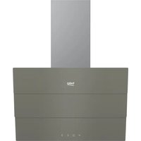
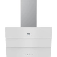
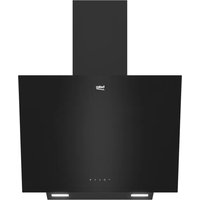
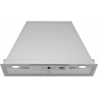
| Product Type | Kitchen Hood |
| Brand | Beko |
| Model | HCB98744AH |
| Width | 898 mm |
| Depth | 490 mm |
| Height | 916 mm |
| Net Weight | 25 kg |
| Gross Weight | 34.4 kg |
| Power Supply | 220-240 V, 50-60 Hz |
| Suction Power | 765 m³/h |
| Motor Power | 270 W |
| Lighting | 1 x 9 W (LED) |
| Fuse | 10 A |
| Air Outlet Diameter | 150 mm (reducible to 120 mm) |
| Minimum Distance Above Hob | 650 mm |
| Number of Speeds | 3 + intensive |
| Grease Filter Type | Washable metallic (dishwasher-safe) |
| Charcoal Filter | For recirculation version, replace every 24 months |
| Color | Anthracite |
| Installation | Exhaust or recirculation |
Frequently Asked Questions - HCB98744AH BEKO
User questions about HCB98744AH BEKO
0 question about this device. Answer the ones you know or ask your own.
Ask a new question about this device
Download the instructions for your Basket in PDF format for free! Find your manual HCB98744AH - BEKO and take your electronic device back in hand. On this page are published all the documents necessary for the use of your device. HCB98744AH by BEKO.
USER MANUAL HCB98744AH BEKO
Please read this user manual first!
Dear Customer,
Thank you for preferring a Beko product. We hope that you get the best results from your product which has been manufactured with high quality and state-of-the-art technology. Therefore, please read this entire user manual and all other accompanying documents carefully before using the product and keep it as a reference for future use. If you handover the product to someone else, give the user manual as well. Follow all warnings and information in the user manual.
Remember that this user manual is also applicable for several other models. Differences between models will be identified in the manual.
Explanation of symbols
Throughout this user manual the following symbols are used:

Important information or useful hints about usage.

Warning for hazardous situations with regard to life and property.
Warning for electric shock.

Packaging materials of the product are manufactured from recyclable materials in accordance with our National Environment Regulations.
Do not dispose of the packaging materials together with the domestic or other wastes. Take them to the packaging material collection points designated by the local authorities.

This product was manufactured using the latest technology in environmentally friendly conditions.
1 Recommendations and Suggestions 4
1.1 Installation 4
1.2 Use ....5
1.3 Maintenance ....5
2 Characteristics 6
2.1 Components....6
2.2 Dimensions 6
2.3 Technical Specifications .....6
3 Installation 7
3.1 Boring the wall .....7
3.2 Mounting the hood body .....7
3.3 Connection....8
3.3.1 Air Outlet In A Ducting Hood Version.....8
3.3.2 Air Outlet In A Recycling Hood Version . . . .9
3.4 Electrical Connection .....9
4 Use 10
4.1 Control panel .....10
5 Maintenance 11
5.1 Grease Filters....11
5.1.1 Cleaning Metal Self- Supporting Grease Filters 11
5.2 Activated charcoal filter (Recirculation version) .....11
5.2.1 Replacing The Activated Charcoal Filter . .11
5.3 Lighting unit....11
1 Recommendations and Suggestions

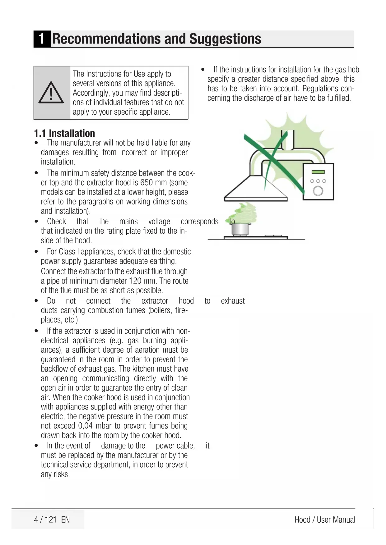
The Instructions for Use apply to several versions of this appliance. Accordingly, you may find descriptions of individual features that do not apply to your specific appliance.
1.1 Installation
- The manufacturer will not be held liable for any damages resulting from incorrect or improper installation.
- The minimum safety distance between the cooker top and the extractor hood is 650 mm (some models can be installed at a lower height, please refer to the paragraphs on working dimensions and installation).
- Check that the mains voltage corresponds that indicated on the rating plate fixed to the inside of the hood.
- For Class I appliances, check that the domestic power supply guarantees adequate earthing. Connect the extractor to the exhaust flue through a pipe of minimum diameter 120 mm. The route of the flue must be as short as possible.
- Do not connect the extractor hood ducts carrying combustion fumes (boilers, fireplaces, etc.).
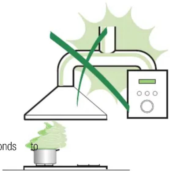
- If the extractor is used in conjunction with non-electrical appliances (e.g. gas burning appliances), a sufficient degree of aeration must be guaranteed in the room in order to prevent the backflow of exhaust gas. The kitchen must have an opening communicating directly with the open air in order to guarantee the entry of clean air. When the cooker hood is used in conjunction with appliances supplied with energy other than electric, the negative pressure in the room must not exceed 0,04 mbar to prevent fumes being drawn back into the room by the cooker hood.
- In the event of damage to the power cable, must be replaced by the manufacturer or by the technical service department, in order to prevent any risks.
- If the instructions for installation for the gas hob specify a greater distance specified above, this has to be taken into account. Regulations concerning the discharge of air have to be fulfilled.
text_image
ends toto exhaust
1 Recommendations and Suggestions
1.2 Use
The extractor hood has been designed exclusively for domestic use to eliminate kitchen smells.
- Never use the hood for purposes other than for which it has been designed.
- Never leave high naked flames under the hood when it is in operation.
- Adjust the flame intensity to direct bottom of the pan only, making sure that it does not engulf the sides.
- Deep fat fryers must be continuously monitored during use: overheated oil can burst into flames.
- Do not flambè under the range hood; risk of fire
- This appliance is not intended for use by persons (including children) with reduced physical, sensory or mental capabilities, or lack of experience and knowledge, unless they have been given supervision or instruction concerning use of the appliance by a person responsible for their safety.
- Children should be supervised to ensure that they do not play with the appliance.
- “CAUTION: Accessible parts may become hot when used with cooking appliances.”
1.3 Maintenance
- Switch off or unplug the appliance from mains supply before carrying out any maintenance work.
- Clean and/or replace the Filters after the specified time period (Fire hazard).
- Clean the hood using a damp cloth and a neutral itliquid detergent.
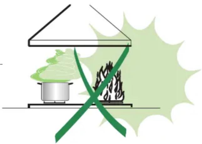
natural_image
Illustration of a cooking setup with a pot and steam rising, crossed by a green X-shaped line (no text or symbols)2 Characteristics
2.1 Components
Ref. Q.ty Product components
1 1 Hood Body complete with: Controls, Light, Suction Unit, Filters, Lower Duct
7 1 PVC Pipe (fitted)
8 1 Inclinable grid (fitted)
9 1 Reduction flange ø 150-120 mm
10 1 Metal cover
Ref. Q.ty Assembly components
11 1 Wall Plugs
11a 2 SB 12/10 Plugs
12a 1 Screws 4,2 x 44,4
Q.ty Documents
1 Instruction Manual
2.2 Dimensions
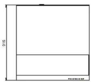
text_image
916 ..........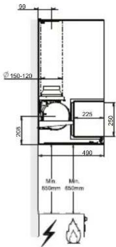
text_image
39 Ø 150-120 208 225 250 490 Min. 650mm Min. 650mm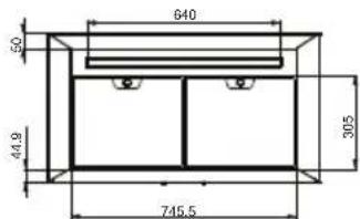
text_image
640 50 44.9 305 745.5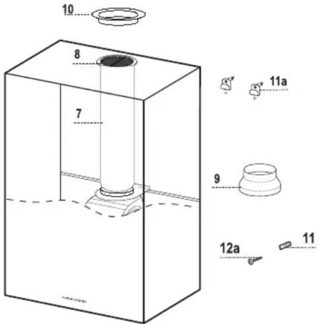
text_image
10 8 7 11a 9 12a 112.3 Technical Specifications
| Width 898 mm | |
| Depth 490 mm | |
| Height 916 mm | |
| Supply voltage 220 - 240 V, 50-60 Hz | |
| Control 3 positions | |
| Suction power 765 m | ^3/_h |
| Motor power | 270 W |
| Lamp power | 1X9 W |
| Fuse | 10 A |
| Air outlet pipe diameter | 150 mm |
| Net weight | 25 kg |
| Gross weight | 34,4 kg |
| Color | Antracite |
Markings on the product or the values stated in other documents supplied with the product are values obtained under laboratory conditions as per relevant standards. These values may vary according to the usage of the product and ambient conditions.
3 Installation
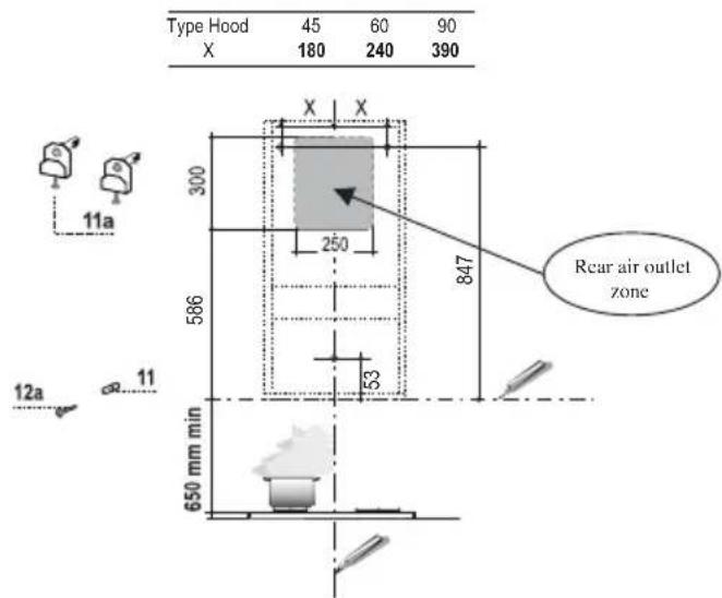
3.1 Boring the wall
text_image
Type Hood 45 60 90 X 180 240 390 X X 300 250 847 Rear air outlet zone 586 53 12a 11 650 mm minIf you want to use the hood in suction version with the air outlet at the back of the hood, make sure to follow the indications given below in the drawing for a correct boring operation of the air outlet opening.
When installing the hood in recycling version it has to be taken into consideration that space remaining between the hood and the upper limit (ceiling or self) is at least 8-10 cm.
On the wall, trace:
- a vertical line up to the ceiling or top limit, at the centre of the area where you intend to fit the hood;
- a horizontal line at: 650 mm min. cooking hob;
- As shown, mark a reference point at 847 mm above the horizontal reference line, and at X mm (X= see table in figure) to the right of the vertical reference line.
- Repeat this operation on the opposite side, checking levelling.
- Drill the points marked using a 12 mm bit
- Insert plugs with screws and brackets 11a in the holes then tighten them.
- As shown, mark a reference point at above the horizontal reference line, at the center of the of the vertical reference line.
- Drill the points marked using a 8 mm bit.
- Insert the plug 11 in the hole.
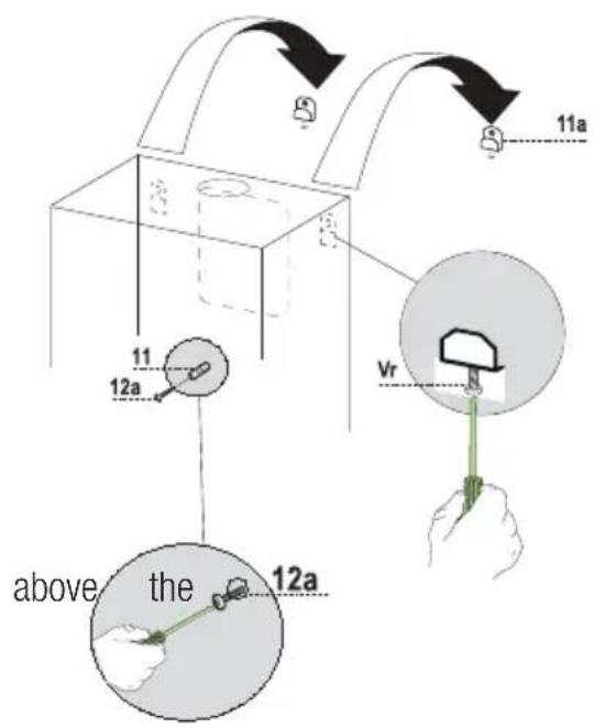
3.2 Mounting the hood body
- Remove the metal grease filters by turning the handles provided.
- Adjust the two screws Vr, on brackets 11a, to a minimum.
- Hook the hood canopy onto the two 11a.
- From inside the hood canopy, adjust the screws Vr to set the Hood Canopy level.
• Tighten the safety screw 12a.
text_image
11a 11 12a Vr above the 12aside,
3 Installation
3.3 Connection
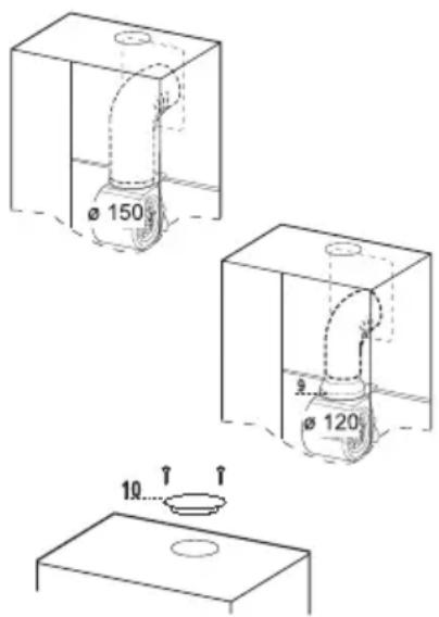
3.3.1 Air Outlet In A Ducting Hood Version
When installing the hood in ducting version, basing on the installer's choice, a rigid or a flexible pipe with a 150 or 120 mm is used in order to connect the hood to the air outlet piping. The pipe connection can be made on the upper part or on the rear side of the hood.
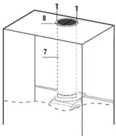
Before connecting the hood to the air outlet ducting remove the lateral air outlet grid 8 and the plastic tube 7. The adapting flange 9 has to be removed only in case the connecting diameter is 150.
text_image
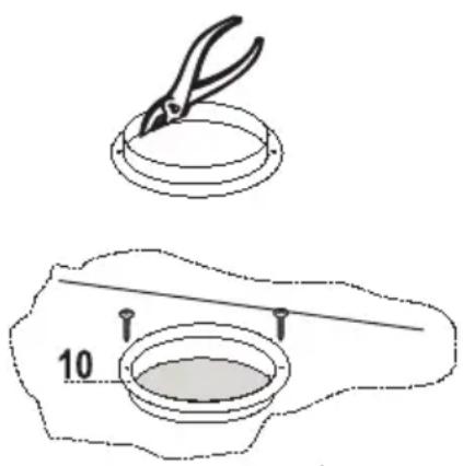
ø 150 ø 120 103.3.1.1 Rear Air Outlet
- When drilling the air outlet hole in the wall proceed in accordance with the scheme in the part concerning the wall drilling.
- Use a pair of tongs when breaking the rear air outlet hole in the wall.
- In case the connection is made by using a 120 mm pipe insert the reduction flange 9 on the hood body outlet.
- Fix the pipe with an adequate quantity of pipe clamps. This material is not supplied together with the hood.
- Remove the charcoal filter if present.
- Fix the metal cover 10 to the upper air outlet hole of the hood by using the screws supplied.
3.3.1.2 Upper Air Outlet
- In case the connection is made by using a 120 mm pipe insert the reduction flange 9 on the hood body outlet.
- Use a pair of tongs when removing the central part of the metal cover 10. Fix the cover to the air outlet hole of the hood by using the screws supplied.
- Fix the pipe with an adequate quantity of pipe clamps. This material is not supplied together with the hood.
- Remove the charcoal filter if present.
text_image
Diagram showing two steps of a hairpin application: first to apply, second to applying a sample into a container with a 10-unit mark.3 Installation
3.3.2 Air Outlet In A Recycling Hood Version
- In case the components requested cycling functioning have been removed earlier these have to be positioned again.
- Put the plastic tube onto the flange 7.
- Place the air outlet grid 8 on the air outlet. Make sure that the position of the grid is correct.
- Make sure that charcoal filters have been placed inside the hood.
text_image
8 73.4 Electrical Connection
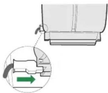
- Connect the hood to the mains through a two-pole switch having a contact gap of at least 3 mm.
- Remove the grease filters (see paragraph Maintenance) being sure that the connector of the feeding cable is correctly inserted in the socket placed on the side of the fan.
natural_image
Diagram showing a mechanical component with a green arrow indicating direction, no text or symbols present4 Use
text_image
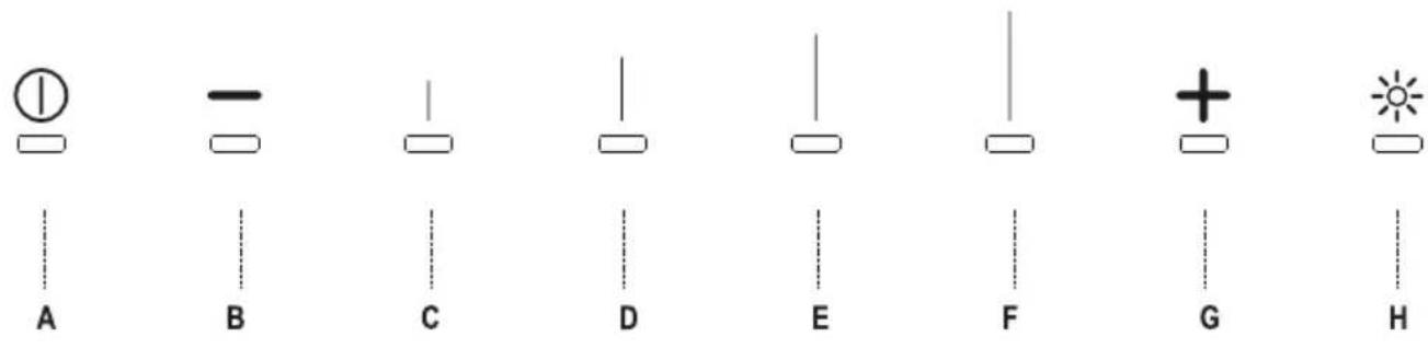
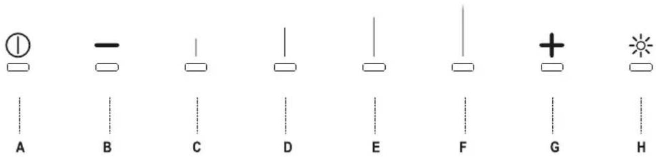
A B C D E F G H4.1 Control panel
| Button Function Led | |
| A Turns the motor On/Off Leds off | |
| B Decreases the speed(Intensive-3-2-1) | Leds C-D-E-F light up according to the speed that is set |
| C Lights up when speed 1 is active | |
| D Lights up when speed 2 is active | |
| E Lights up when speed 3 is active | |
| F Lights up when Intensive speed is active | |
| G Increases the speed.(1-2-3-Intensive) | Leds C-D-E-F light up according to the speed that is set |
| H Turns the lights ON/OFF at maximum intensityPress and hold the button for 2 seconds to turn the lights on at intermediate intensity | Led H lights up |
5 Maintenance
5.1 Grease Filters
5.1.1 Cleaning Metal Self- Supporting Grease Filters
- The filters must be cleaned every 2 months of operation, or more frequently for particularly heavy usage, and can be washed in a dishwasher.
- Remove the filters one at a time by pushing them towards the back of the group and pulling down at the same time.
- Wash the filters, taking care not to bend them. Allow them to dry before refitting.
- When refitting the filters, make sure handle is visible on the outside.
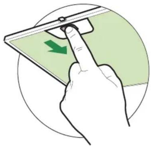
natural_image
Illustration of a hand pressing a green arrow on a device screen, enclosed in a circular frame (no text or symbols)5.2 Activated charcoal filter (Recirculation version)
These filters are not washable and cannot be regenerated, and must be replaced approximately every 4 months of operation, or more frequently with heavy usage.
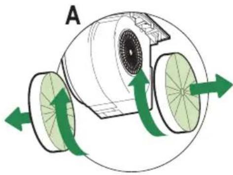
5.2.1 Replacing The Activated Charcoal Filter
- Remove the metal grease filters
- Remove the saturated activated charcoal filter as shown (A).
• Fit the new filters (B).
• that the replace the metal grease filters.
natural_image
Diagram of a mechanical device with green arrows indicating rotational or directional motion (no text or symbols)
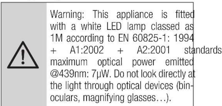
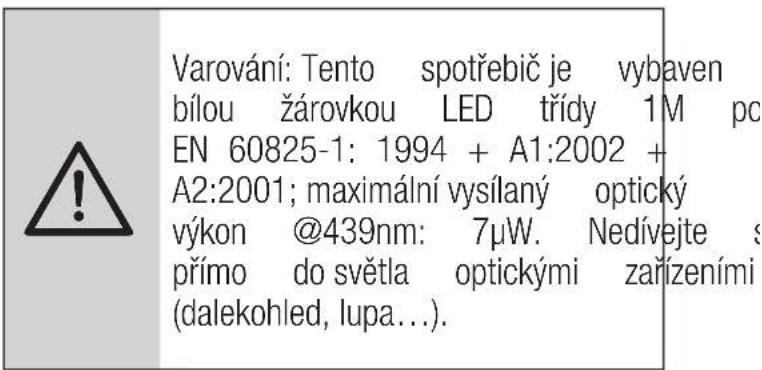
5.3 Lighting unit
text_image
Warning: This appliance is fitted with a white LED lamp classed as 1M according to EN 60825-1: 1994 + A1:2002 + A2:2001 standards maximum optical power emitted @439nm: 7μW. Do not look directly at the light through optical devices (bin- oculars, magnifying glasses...).- For replacement contact technical support. ("To purchase contact technical support")
text_image
916 400mm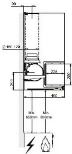
text_image
99 ②150-120 205 225 250 490 Min. 650mm Min. 650mm p
text_image
640 50 44.9 305 745.5
text_image
10 8 7 11a 9 12a 11text_image
Diagram showing two steps of a tool application: top shows a pliers on a circular base, bottom shows a measuring cup with a scale and a numbered label '10'.3 Installation
natural_image
Diagram showing a mechanical component with an inset view of a pipe fitting and a green arrow indicating direction (no text or symbols present)4 Nutzung


4.1 Bedienfeld
natural_image
Illustration of a hand pressing down on a device with a green arrow indicating left motion (no text or symbols)natural_image
Diagram of a mechanical device with green directional arrows indicating rotation or movement (no text or symbols)5.3 Lampeneinheit
Cher client, chère cliente,
natural_image
Illustration of a cooking setup with a pot and steam rising, crossed by a green ribbon (no text or symbols)2 Caractéristiques
2.1 Composants
text_image
Diagram showing two steps of a hairpin application: top is using a ring-shaped tool, bottom is a circular component with a numbered label '10' indicated.l'aide d'un
3 Installation
natural_image
Diagram showing a mechanical component with a green arrow indicating direction, no text or symbols present4 Utilisation

text_image
A B C D E F G Hnatural_image
Illustration of a hand pressing down on a device with a green arrow indicating left motion (no text or symbols)natural_image
Diagram of a mechanical device with green directional arrows indicating rotational flow, labeled A and B (no text or symbols present)text_image
Diagram showing two steps of a hairpin application: top view with scissors on a circular base, bottom view with a measuring tool and scale labeled '10'.natural_image
Diagram showing a mechanical component with a green arrow indicating direction, no text or symbols present4 Użytkowanie

text_image
A B C D E F G Hnatural_image
Illustration of a hand pressing a green arrow on a smartphone screen, enclosed in a circular frame (no text or symbols)natural_image
Diagram of a mechanical device with green directional arrows indicating motion or force, labeled A and B (no text or symbols present)5.3 Oświetlenie

natural_image
Illustration of a laboratory setup with a conical flask, test tube, and heating device (no text or symbols)je treba prostoru,
natural_image
Illustration of a cooking setup with a pot and steam rising, crossed by a green X-shaped line (no text or symbols)2 Značilnosti
2.1 Komponente
Ref. Kol. Komponente izdelka
1 1 Celotni osrednji del nape z/s: krmilniki, lučko, sesalno enoto, filtri, spodnjo cevjo
text_image
Diagram showing two steps of a hairpin application: top is applying a cup to a ring, bottom is applying a container with a handle labeled '10'.natural_image
Diagram showing a mechanical component with a green arrow indicating direction, no text or symbols present4 Uporaba
text_image
A B C D E F G H4.1 Nadzorna plošča
| Gumb Funkcija Lučka LED | |
| A Izklopi/vklopi motor LED lučke ugasnjene | |
| B Zniža hitrost(intenzivno-3-2-1) | LED lučke C-D-E-F zasvetijo glede na nastavljeno hitrost |
| C Sveti, kadar je aktivna hitrost 1 | |
| D Sveti, kadar je aktivna hitrost 2 | |
| E Sveti, kadar je aktivna hitrost 3 | |
| F Sveti, kadar je aktivna intenzivna hitrost | |
| G Zviša hitrost.(1-2-3-intenzivno) | LED lučke C-D-E-F zasvetijo glede na nastavljeno hitrost |
| H Vklopi/izklopi lučke pri največji intenzivnostiPritisnite in zadržite gumb za 2 sekundi, da prižgete lučke pri vmesni hitrosti | LED lučka H zasveti |
5 Vzdrževanje
natural_image
Illustration of a hand pressing a device with a green arrow indicating left motion (no text or symbols)5.2 Filter z aktivnim ogljikom (različica s kroženjem)
natural_image
Diagram of a mechanical device with green directional arrows indicating rotational flow, labeled A and B (no text or symbols present)5.3 Luč
natural_image
Illustration of a chemical experiment setup with a conical flask, thermometer, and smoke rising (no text or symbols)junto con
text_image
916 a50000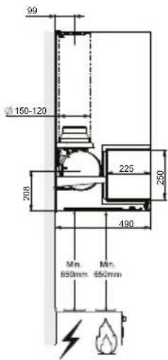
text_image
99 Ø150-120 208 225 250 490 Mn. 650mm Mn. 650mm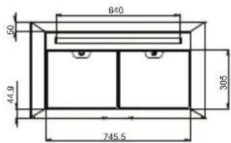
text_image
640 50 44.9 305 745.5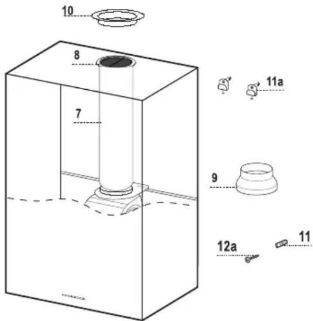
text_image
10 8 7 11a 9 12a 11text_image
Diagram showing two steps of a hairpin application: top view with a clip, bottom view with a circular object labeled '10'3 Instalación
natural_image
Diagram showing a mechanical component with an inset view of a pipe fitting and a green arrow indicating direction (no text or symbols present)4 Uso

text_image
A B C D E F G H4.1 Panel de control
natural_image
Illustration of a hand pressing a green arrow on a device screen, enclosed in a circular frame (no text or symbols)natural_image
Diagram of a mechanical device with green directional arrows indicating rotational flow, labeled A and B (no text or symbols present)text_image
Diagram showing two steps of a hairpin application: first to apply, second to apply with a numbered label '10'.3 Inštalácia
natural_image
Diagram showing a mechanical component with an inset view of a disassembly or assembly process (no text or symbols present)4 Používanie

text_image
A B C D E F G H4.1 Ovládací panel
natural_image
Illustration of a hand pressing down on a smartphone screen with a green arrow indicating left-side motion (no text or symbols)natural_image
Diagram of a mechanical device with green directional arrows indicating rotation or movement (no text or symbols)natural_image
Illustration of a chemical experiment setup with a conical flask, thermometer, and smoke rising (no text or symbols)1 Aanbevelingen en suggesties
1.2 Gebruik
Ref. hvh Montageonderdelen
11 1 Wandpluggen
11a 2 SB 12/10 pluggen
12a 1 Schroeven 4,2 x 44,4
Hvh Documenten
natural_image
Diagram showing a mechanical component with an inset view of a green arrow indicating direction (no text or symbols present)4 Gebruik

text_image
A B C D E F G Hnatural_image
Illustration of a hand pressing down on a device with a green arrow indicating left motion (no text or symbols)natural_image
Diagram of a mechanical device with green directional arrows indicating rotation or movement (no text or symbols)natural_image
Illustration of a chemical experiment setup with a conical flask, thermometer, and gas being heated by a steaming lamp (no text or symbols)natural_image
Illustration of a cooking setup with a pot and smoke, crossed by a green ribbon, against a light green background (no text or symbols)2 Caratteristiche
2.1 Componenti
natural_image
Simple line drawing of a rectangular frame with a vertical dimension labeled 216 (no text or symbols beyond the number)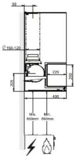
text_image
90 Ø 150-120 208 225 250 490 Mn. 650mm Mn. 650mm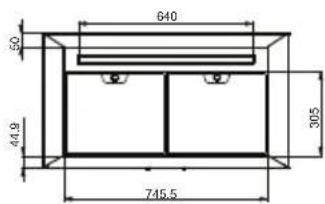
text_image
640 50 44.9 305 745.5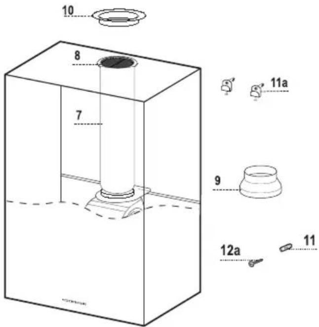
text_image
10 8 7 11a 9 12a 11text_image
Diagram showing two steps of a hairpin application: first to apply, second to apply with a numbered label '10'3 Installazione
natural_image
Mechanical component diagram showing a bracket with a green arrow indicating direction (no text or symbols present)4 Uso

text_image
A B C D E F G Hnatural_image
Illustration of a hand pressing a device on a green screen, with a green arrow indicating the left side (no text or symbols present)natural_image
Diagram of a mechanical device with green directional arrows indicating rotation or movement (no text or symbols)natural_image
Illustration of a chemical experiment setup with a conical flask, thermometer, and gas stove (no text or symbols)natural_image
Illustration of a cooking setup with a pot and smoke, crossed by a green ribbon, against a light green background (no text or symbols)2 Caracteristici
2.1 Componente
Ref. Cant. Componente produs
text_image
Diagram showing two steps of a hairpin application: top view with scissors on a circular base, bottom view with a measuring tool and a labeled component '10'.3 Instalare
natural_image
Diagram showing a mechanical component with an inset view of a pipe fitting and a green arrow indicating direction (no text or symbols present)4 Utilizare

text_image
I - A B C D E F G Hnatural_image
Illustration of a hand pressing a green arrow on a device screen, enclosed in a circular frame (no text or symbols)5.2 Filtru cu carbon activ (versiunea cu recirculare)
natural_image
Diagram of a mechanical device with green directional arrows indicating rotation or movement (no text or symbols)5.3 Lampa

text_image
Diagram showing two steps of a hairpin application: top view with scissors on a circular base, bottom view with a measuring tool and a labeled point '10'natural_image
Diagram showing a mechanical component with a green arrow indicating direction, no text or symbols present4 Použití

A

B

C
D
E
F

G

H
4.1 Ovládací panel
natural_image
Illustration of a hand pressing a green arrow on a device screen, enclosed in a circular frame (no text or symbols)natural_image
Diagram of a mechanical device with green directional arrows indicating rotation or movement (no text or symbols)5.3 Osvětlení
natural_image
Illustration of a chemical experiment setup with a conical flask, thermometer, and smoke rising (no text or symbols)natural_image
Illustration of a cooking setup with a pot and steam rising, crossed by a green smoke cover (no text or symbols)2 Характеристики
2.1. Компоненты
text_image
Diagram showing two steps of a hairpin application: first to apply, second to apply with a numbered label '10'3 Установка
natural_image
Diagram showing a mechanical component with a green arrow indicating direction, no text or symbols present4 Использование

A

B


C

D
E
F

G

H
natural_image
Illustration of a hand pressing down on a smartphone screen with a green directional arrow (no text or symbols)natural_image
Diagram of a mechanical device with green directional arrows indicating rotation or movement (no text or symbols)5.3. Освещение