Smart Generator - Power bank ECOFLOW - Free user manual and instructions
Find the device manual for free Smart Generator ECOFLOW in PDF.
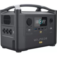
| Product type | Portable inverter generator |
| Brand | EcoFlow |
| Model | Smart Generator |
| Dimensions (L × W × H) | 597 × 296 × 475 mm |
| Net weight | 29.3 kg |
| Rated power | 1,800 W (peak 1,900 W) |
| Rated voltage | 230 V / 50 Hz |
| Power factor | 1 |
| DC output | 42-58.8 V, max current 32 A |
| Engine | R80-i, single cylinder 4-stroke, 79.7 cm³, forced air cooling |
| Fuel | Unleaded, tank 4 L |
| Engine oil | SAE SJ 10W-40, capacity 0.38 L |
| Runtime | 3.5 h at full load |
| Noise level (7 m) | 56-67 dB at full load |
| Spark plug | Model A5RTC, gap 0.6-0.8 mm |
| Starting mode | Electric (button) and manual (recoil) |
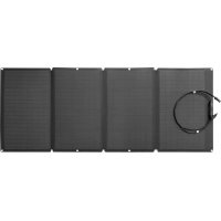
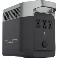
| Main features | DC charge for DELTA Max/Pro batteries, EcoFlow app, ECO mode, auto shutdown, CO detection |
| Routine maintenance | Oil change every 50 h, air filter cleaning every 10 h in dusty environments, spark plug check |
| Safety | Carbon monoxide detection (shutdown+alarm), overload protection, temperature, battery |
| Spare parts & repairability | Spark plug, air filter, fuel strainer, oil; maintenance by dealer for carburetor and valve clearance |
| Operating temperature | -15 °C to 40 °C |
| Warranty | Refer to enclosed warranty card |
Frequently Asked Questions - Smart Generator ECOFLOW
User questions about Smart Generator ECOFLOW
0 question about this device. Answer the ones you know or ask your own.
Ask a new question about this device
Download the instructions for your Power bank in PDF format for free! Find your manual Smart Generator - ECOFLOW and take your electronic device back in hand. On this page are published all the documents necessary for the use of your device. Smart Generator by ECOFLOW.
USER MANUAL Smart Generator ECOFLOW
text_image
ECOFLOW SMART GENERATORDisclaimer
Users are expected to read this User Manual carefully and ensure they have fully understood the content before using this product. Please keep this User Manual for future reference. Any incorrect usage may result in severe injury to the user or others, damage to the product or loss of property. By using this product, the user will be deemed as having understood, recognized and accepted all the terms and contents of the User Manual, and will be responsible for any incorrect usage, and all the consequences arising therefrom. EcoFlow hereby disclaims any liability for any losses due to the user's failure to use the product according to the User Manual.
Subject to compliance with laws and regulations, our company has the final right to interpret this document and all documents of and related to this product. Any update, revision or termination of the content thereof, if necessary, will be made without prior notice, and users must visit the official website of EcoFlow for the latest information regarding the product.
Contents
1. Safety Guidelines 1
1.1 Safety Warning 1
1.2 Safety Instructions 1
1.3 Important Labels 2
2. Quick Start 3
2.1 Appearance Description 3
2.2 Introduction to the Icons on the Display Screen 5
2.3 Before You Use the Product 6
2.4 Using the Product 9
--2.4.1 Startup 9
--2.4.2 Turning Off 10
--2.4.3 AC Connections 10
--2.4.4 DC Charging 11
2.4.4.1 Charging the DELTA Max or the DELTA Pro 11
2.4.4.2 Charging the DELTA Max Extra Battery Pack or the DELTA Pro Extra Battery Pack 12
--2.4.5 Using the App 12
--2.4.6 Application Range 13
--2.4.7 Special Requirements 13
3. Maintenance and Servicing 14
3.1 Checking the Spark Plug 15
3.2 Adjusting the Carburetor 15
3.3 Replacing the Engine Oil 16
3.4 Air Filter 16
3.5 Fuel Filter Strainer 17
3.6 Muffler 17
4. Storage and Transportation 18
4.1 Draining the Fuel 18
4.2 Storing the Generator 18
4.3 Rechargeable Battery 18
4.4 Use after storage 19
4.5 Transportation 19
5. Faults and Troubleshooting 20
6. Parameters and Specifications 21
7. Package List 21
8. Circuit Diagram 22
1. Safety Guidelines
1.1 Safety Warning
The safety of you and others, as well as of property are of the primary importance. Please carefully read the extremely important safety warnings we have written in the User Manual and the sticker of the generator set. This is to remind you of the potential dangers which may harm you and others. Before each safety warning is a symbol and one of the three following words: danger, warning or caution.
These words indicate:

If you fail to follow the instructions, your life will be at risk or you will be severely injured.
If you fail to follow the instructions, your life may be at risk or you may be seriously injured.
If you fail to follow the instructions, your generator set and other property may be damaged.
1.2 Safety Instructions
Please read the User Manual carefully before using the generator in order to avoid accidents.

natural_image
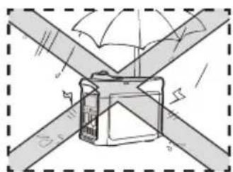
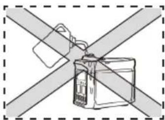
Diagram showing a cross-shaped structure with a box and window, no text or symbols presentDo not use indoors and keep away from doors, windows and vents
natural_image
Diagram of a mechanical device with intersecting beams and a central component, no visible text or symbolsDo not use in damp environments

natural_image
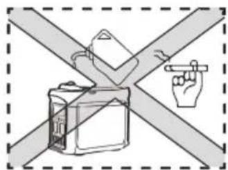
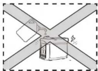
Diagram of a device with two crossed bands and a central connector (no text or symbols)Make sure that no fuel is spilled when refueling
text_image
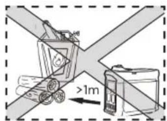
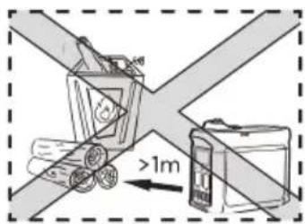
Diagram showing a vehicle with two wheels and a battery, labeled with distance '1m' and 'd'Keep any combustibles at least 1m / 3ft away
text_image
Diagram showing a hand pointing at a device against a cross-shaped barrier, with no text or symbols present.Do not smoke when refueling Switch off the engine before refueling
natural_image
Diagram of a device with two crossed bands and a warning symbol (no text or labels)Earthing the Generator
The generator is equipped with system grounding, which is used to connect the generator's frame components to the ground terminal in the AC outlet. The system grounding doesn't connect to the AC neutral.
Connect the Generator to the Electrical System
Do not connect the generator to the electrical system of a building, unless an isolation switch has been properly installed by a licensed electrician. Please comply with all applicable laws and electrical regulatory requirements.
Caution
Keep the air inlets in the side of front panel, the muffler and the bottom of generator clean and unblocked and prevent any debris, mud or water from entering. The generator, the controller or the engine may be damaged if these air inlets become blocked. Do not transport, store or use the generator together with other products. Any oil leaks may damage the generator or endanger your personal safety as well as your property.
1.3 Important Labels
Please refer the following stickers carefully before starting to use the product.
| WARNING | ||
| Read the owner's manual and all labels before operating. | ||
| Only operate in well-ventilated areas. Using a generator indoors CAN KILL YOU IN MINUTES Generator exhaust contains carbon monoxide. This is a poison you cannot see or smell. Tampering with this CO alarm system will cause Carbon Monoxide poisoning! | ||
| Electrocution can occur if generator is used in rain, snow, or near water. Keep this unit dry at all times. Electrocution or property damage can occur. Refer to the owner's manual. | Backfeed into utility system can cause property damage and electrocution hazard. Do not connect the generator to a building's electrical system unless an isolation switch has been properly installed by a licensed electrician. | |
| Check for spilled fuel or fuel leaks. Stop engine before refueling. Do not operate near flammable materials. | ||
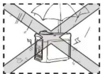
| When operating the generator: Never place a partition or other barrier around the generator. Do not cover the generator with a box. Do not place any objects on the generator. Turn the fuel tank cap air vent knob to "OFF" after the engine has completely cooled down. | ||
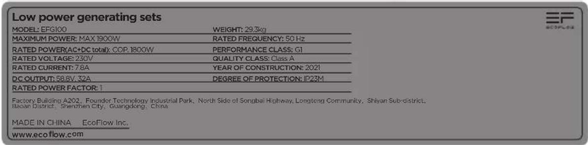
text_image
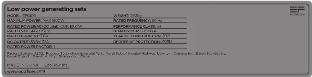
Low power generating sets MODEL: EFG100 WEIGHT: 29.3kg MAXIMUM POWER: MAX 1800W RATED FREQUENCY: 50 Hz RATED POWER(AC+DC total): COP. 1800W PERFORMANCE CLASS: CI RATED VOLTAGE: 230V QUALITY CLASS: Class A RATED CURRENT: 7.8A YEAR OF CONSTRUCTION: 2021 DC OUTPUT: 58.8V, 32A DEGREE OF PROTECTION: IP23M RATED POWER FACTOR: 1 Factory Building A202, Founder Technology Industrial Park, North Side of Songbai Highway, Longtong Community, Shiyan Sub-district, Bao'an District, Shenzhen City, Guangdong, China MADE IN CHINA EcoFlow Inc. www.ecoflow.com
text_image
WARNING Operation of this equipment may create sparks that can start fires around dry vegetation. A spark arrestor may be required, The operator should contact local fire agencies for laws or regulations relating to fire prevention requirements. Hot exhaust can bum you, Stay away if engine has been running. ↓ ECORLOW2. Quick Start
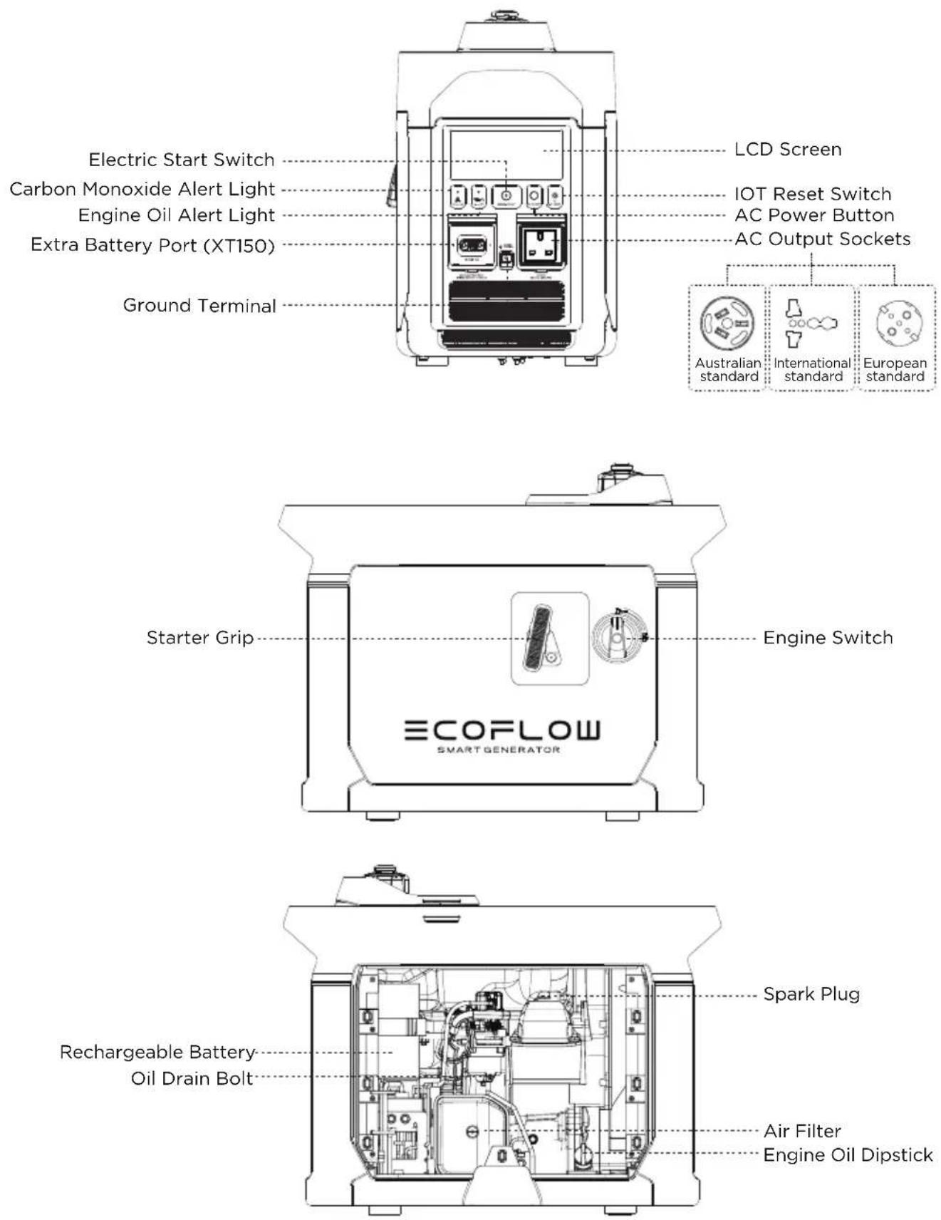
2.1 Appearance Description
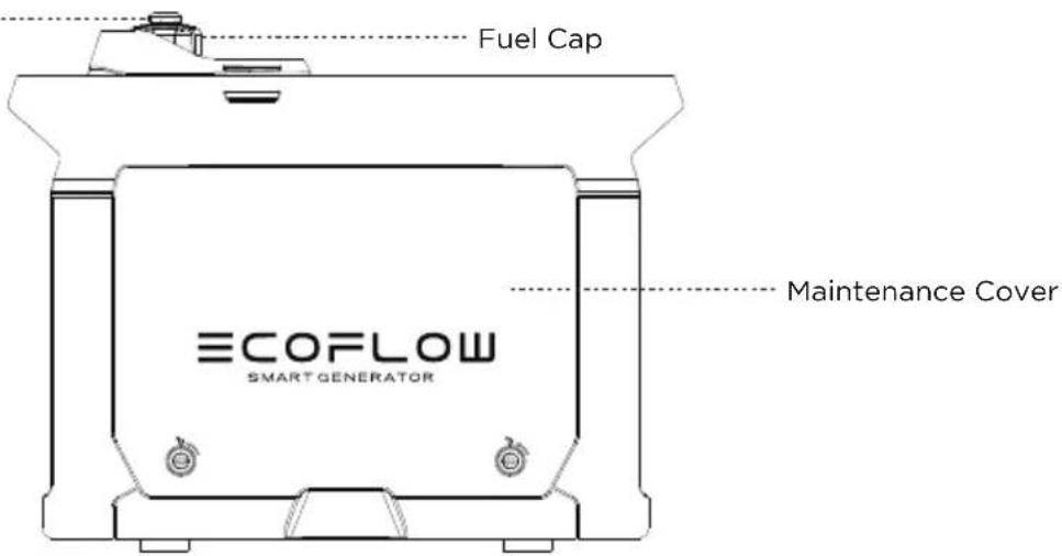
Fuel Cap Breather Valve
text_image
Fuel Cap ECOFLOW SMART GENERATOR Maintenance Cover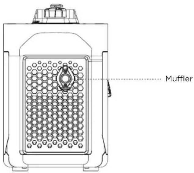
text_image
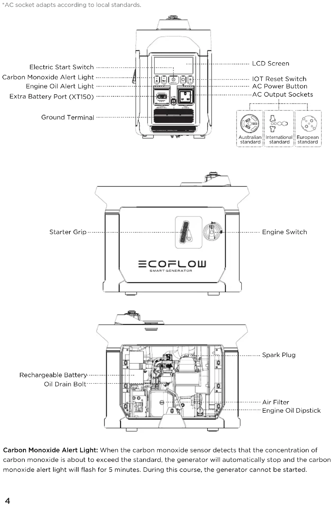
Muffler*AC socket adapts according to local standards.
text_image
Electric Start Switch Carbon Monoxide Alert Light Engine Oil Alert Light Extra Battery Port (XT150) Ground Terminal LCD Screen IOT Reset Switch AC Power Button AC Output Sockets Australian standard International standard European standard Starter Grip Engine Switch ECOFLOW SMART GENERATOR Spark Plug Rechargeable Battery Oil Drain Bolt Air Filter Engine Oil DipstickCarbon Monoxide Alert Light: When the carbon monoxide sensor detects that the concentration of carbon monoxide is about to exceed the standard, the generator will automatically stop and the carbon monoxide alert light will flash for 5 minutes. During this course, the generator cannot be started.
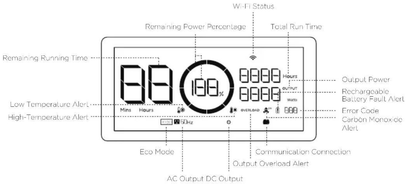
2.2 Introduction to the Icons on the Display Screen
text_image
Wi-Fi Status Remaining Power Percentage Total Run Time Remaining Running Time 88 180% Mins Hours Hours OUTPUT Watts Output Power Rechargeable Battery Fault Alert Error Code Carbon Monoxide Alert Low Temperature Alert High-Temperature Alert Eco Mode 5DHz OVERLOAD Communication Connection Output Overload Alert AC Output DC OutputRemaining Power Percentage: If the remaining fuel level is lower than 600 mL/20.3 oz., the indicator will be at 0% charge and flash to warn you.
Wi-Fi Status: After pressing the IOT button for 3 seconds, the Wi-Fi status will flash on the LCD screen which indicates that the product is ready for pairing. There're two ways to connect the product with the App, either directly connect to the product's hotspot or using the Internet. If the App is successfully connected to the product's hotspot, the icon will keep flashing; if it is successfully connected to the Internet, the icon will stay on.
Error Code: Please refer to the EcoFlow app for specific information on error codes.
ECO Mode: In ECO mode, the Smart Generator will adjust its rotational speed to match the output power demand, in order to conserve fuel and reduce noise. This is the default mode. You can modify the mode settings in the EcoFlow app. For details please refer to 2.4.5.
2.3 Before You Use the Product
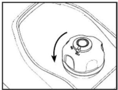
Refueling

Danger
Please read the Safety Guidelines carefully before refueling as fuel is inflammable and toxic. Do not overfill the fuel tank, as fuel may expand and spill out when the fuel tank warms up. Be sure to tightly close the fuel cap after refueling.
natural_image
Diagram of a mechanical component with an arrow indicating rotational motion (no text or symbols)Open fuel cap
Caution
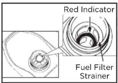
Clean away the residual fuel with a clean and soft cloth after refueling to avoid damage to the rubber shell. Please use unleaded fuel rather than leaded fuel which may severely damage the internal parts of generator. Take off the fuel cap and fill up until the red indicator.
text_image
Red Indicator Fuel Filter StrainerRefueling
Recommended fuel: unleaded fuel Fuel tank capacity: 1.05 gal. / 4 L
Caution
There is no engine oil in the generator when delivered from the factory. Do not start up the generator until after adding sufficient engine oil. Do not tilt the generator when adding engine oil, to prevent damage to the generator due to adding excessive oil.
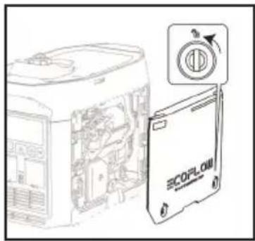
- Place the generator on a level plane.
- Turn the maintain cover knob to and take off the maintenance cover.
- Unscrew the lid and oil dipstick.
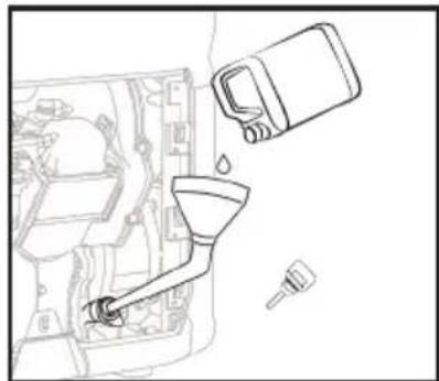
- Inject the specified amount of recommended engine oil, and screw the lid and oil dipstick closed tightly. Reinstall the maintenance cover and turn the knob to Closed.
Recommended engine oil: SAE SJ 10W-40
Grade of recommended engine oil: API Grade SJ or higher
Oil capacity: 0.1 gal. / 0.38 L
text_image
Technical diagram showing a device with internal components and a labeled 'SCOPLOW' card, alongside a circular icon with an arrow.Removing the maintenance cover
natural_image
Line drawing of a car interior with a funnel, water drop, and spray bottle (no text or symbols)Refilling the engine oil
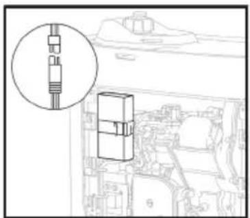
Rechargeable Battery Connection
The generator cannot be started by the Electric Start switch unless connected to the internal battery.
Turn the maintain cover knob to ☐, take off the maintenance cover and connect the positive and the negative wires of the battery respectively.
natural_image
Technical line drawing of a mechanical component with an inset magnified detail (no text or symbols)Connecting the positive and negative wires
Warning
Please check the following components carefully each time before using the generator.
a) Check the fuel level
Take off the fuel cap and check the fuel level. Inject more fuel into the tank if the fuel level is too low.
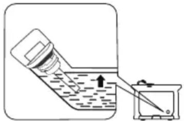
b) Check the engine oil level
- Make sure there are no engine oil leaks.
-
Check the engine oil level. If the oil level is low, the engine oil alarm system may shut off the engine.
-
Unscrew the lid, take out the oil dipstick and wipe it clean.
- Dip the oil dipstick into the oil filler without screwing it in, and check the oil level.
- Add the recommended amount of engine oil if the oil level is low.
- Screw the oil dipstick and lid firmly shut.
natural_image
Simple line drawing of a bottle being poured into a container with an arrow indicating liquid level (no text or symbols)Engine oil level check
c) Check whether the rechargeable battery is connected correctly
Turn the maintain cover knob to Open, take off the maintenance cover and check whether the positive and the negative wires of battery are connected correctly.
Malfunctions While Running
Check for any issues while the generator is running and consult EcoFlow for further technical support if necessary.
2.4 Using the Product
Danger
- Read the Safety Guidelines before use.
- Do not use the generator in a closed space as the exhaust fumes may result in a loss of consciousness or even death. Use it in a well-ventilated place.
- Do not connect the AC Output Socket with any electrical equipment before starting the generator.
Tips: The generator is used at 5 °F -104 °F (-15 °C—40 °C). The generator can operate at rated power under standard atmospheric conditions (“standard atmospheric conditions” - ambient temperature 77°F (25 °C)-atmospheric pressure 100KPA - relative humidity 30%). Once the temperature, humidity and altitude exceed standard atmospheric conditions, the output of the generator will drop. Using for a long time in a high temperature (above 95°F /35 °C) environment will affect the service life of the generator and the built-in battery. Moreover, if the generator is used in any narrow space, its load must be reduced as the generator cooling is affected.
2.4.1 Startup
text_image
OFF OFF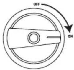
text_image
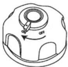
OFF ON- Turn the fuel cap breather valve knob to "ON". 2. Turn the Engine Switch to "ON".
The generator can be started using any of the four methods below:
a) Electric Start Switch
Press and hold the Electric Start Switch for 2 seconds to execute the start-up program and start up the generator.
Tips: To save battery power consumption, when the Engine Switch is at the "ON" position, if the generator fails to start up, the power will be disconnected after 3 mins and the display screen will switch off. In this situation, press the start button to activate the screen display to then re-enable the Electric Start Switch.
natural_image
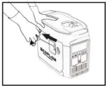
Line drawing of hands operating a device labeled 'SCORILOA' with a handle, showing no text or symbols beyond the label.Manual start
b) Manual start
Pull the Manual Starter Grip until the line tightens and push it by force.
Tips: When starting by hand, it is necessary to hold the generator still to prevent it from tilting or tumbling during the pull-push process.
c) Self-start, see paragraph 2.4.4
d) Starting through the app, see paragraph 2.4.5
Tips: When the ambient temperature is below 32^ F ( 0^ C), the engine will need to warm up for three minutes after being started, during which time no load should be loaded.
2.4.2 Turning off
To turn the engine off in an emergency, turn the engine switch to the "OFF" position. In any other circumstances, please follow the below steps.
- Switch off all electrical equipment and disconnect them from the generator.
- There are four methods to turn off the generator:
a) Using the Engine Switch: Turn the Engine Switch to "OFF" to turn off the generator.
b) Using the Electric Start button: Press and hold the Electric Start button for 2 seconds to stop the engine.
c) Automatic shutdown: If the AC Power Button is turned off, this generator will automatically stop when the DC charging is completed. Refer to 2.4.4.
Tips: When the AC Power Button and DC output are turned off, it will automatically stop after 10mins to save fuel.
d) APP shutdown, refer to 2.4.5.
- Wait until the generator is completely cooled down, then turn the Engine Switch and the fuel cap breather valve knob to "OFF".
2.4.3 AC Connections
- Start the generator.
- Insert the plug into the AC Output Socket and check that the on-screen AC output port icon is illuminated.
- Switch on the electrical equipment.
Tips: During the operation of the generator set, the AC output can be turned on and off through the AC switch. If the generator supplies power to multiple loads or electrical equipment, please start electrical equipment in descending order, according to the size of the load.

Warning
Switch off all electrical equipment before inserting plugs.
Caution
Make sure that all electrical equipment including wires and plugs are in good condition before being connected to the generator, and confirm that all loads carried by the generator are within the rated load range and that the load current is within the rated current range.
Tips: Make sure that the generator is grounded. If any electrical equipment needs to be grounded, the generator must also be grounded.
2.4.4 DC Charging
2.4.4.1 Charging the DELTA Max or the DELTA Pro
- Turn the fuel cap breather valve knob to "ON" (see Step 1 in paragraph 2.4.1).
- Turn the Engine Switch to "ON" (see Step 2 in paragraph 2.4.1).
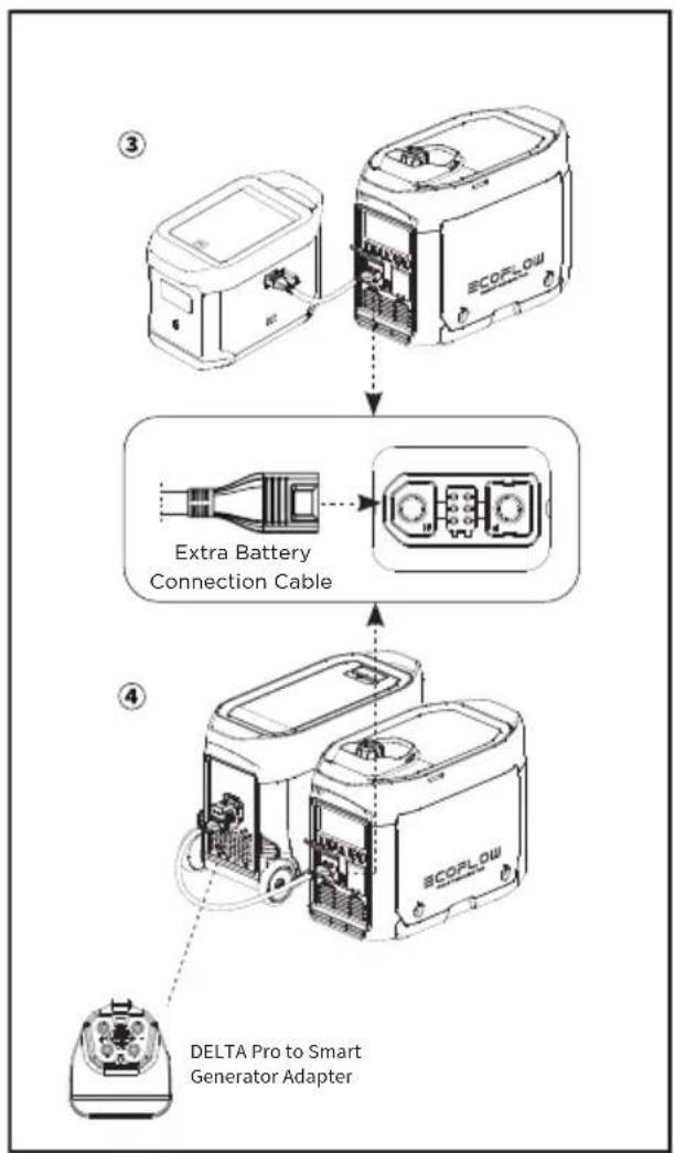
- Connect with the DELTA Max ① or the DELTA Pro ② through the 5m/16.4ft Extra Battery Connection Cable*.
- If the remaining power of the DELTA Max or the DELTA Pro falls to the lower limit, it will send a request to the generator to recharge. The generator will respond and start recharging.
Tips: If the remaining power of the DELTA Max or the DELTA Pro does not fall to the lower limit, the generator can be started by hand to start recharging.
- When the remaining power of DELTA Max or DELTA Pro reaches the upper limit, a request will be sent to the generator set to stop charging, and the generator set will respond and automatically stop.
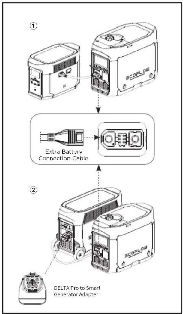
flowchart
graph TD
    A["ECOPLOW Device ①"] --> B["Extra Battery Connection Cable"]
    B --> C["DELTA Pro to Smart Generator Adapter"]
Tips: In the self-starting mode, the AC output of the generator is off by default; If the AC Power Button is turned on, the generator will not automatically stop when the DC charging is completed; The upper and lower limits may be set on the app. The upper limit is 100% by default and the lower limit is 20% by default. When used together with the DELTA Max or the DELTA Pro for recharging, to improve the utilization efficiency of fuel, it is recommended to set the upper limit as 80%. When charging with DC, the AC switch can be turned on for AC output. The total power of DC+AC is 1800 W, with AC output as the priority.
* The DELTA Pro needs to use the dedicated adaptor plug, which is included in the DELTA Pro standard configuration.
2.4.4.2 Charging the DELTA Max Extra Battery Pack or the DELTA Pro Extra Battery Pack
- Turn the fuel cap breather valve knob to "ON" (see Step 1 in paragraph 2.4.1).
- Turn the Engine Switch to "ON" (see Step 2 in paragraph 2.4.1).
- Connect to the DELTA Max Extra Battery③ or DELTA Pro Extra Battery④ with the 5m/16.4ft Extra Battery Connection Cable*.
- Switch on the DELTA Max Extra Battery or DELTA Pro Extra Battery and it will send a request to the generator to recharge. The generator will respond and start recharging.
- When the DELTA Max Extra Battery or DELTA Pro Extra Battery is fully recharged, it will send a request to the generator to stop charging. The generator will respond and stop DC recharging.
* The DELTA Pro Extra Battery Pack needs to use the dedicated adaptor, which is included in the DELTA Pro standard configuration.
flowchart
graph TD
    A["SCOPLOW Device"] --> B["Extra Battery Connection Cable"]
    B --> C["DELTA Pro to Smart Generator Adapter"]
2.4.5 Using the App
You can control and view the information and data of the product through the EcoFlow app.
Read the EcoFlow App user guide and access the download link here:
https://ecoflow.com/pages/ecoflow-app.

text_image
QR code image containing encoded data, no visible human-readable text2.4.6 Application Range
Please make sure that the total load of the generator is within the rated range before using the generator, or otherwise the generator may be damaged.
| Application |  |  |  |
| Power Factor 1 0.8-0.95 | 0.4-0.75(Efficiency 0.85) | ||
| Output | ≤1800 W | ≤1440 W | ≤612 W |
Caution
When this generator is supplying power to precision instruments, electronic controllers, personal computers and microcomputers, please keep the generator a sufficient distance away from any of the foregoing equipment to avoid electromagnetic interference, and at the same time, to ensure that the generator will not be interfered with by these electronic devices.
If this generator is used to supply power to medical devices, it is recommended to consult with the corresponding equipment manufacturers and technicians first. This is because some electronic equipment or general purpose machines in hospitals require a strong current upon startup and may not be able to use the generator. Please contact the equipment manufacturer for confirmation even if the respective start parameters of the equipment satisfy the conditions listed in the table above.
2.4.7 Special Requirements
Warning
- There may be local laws or regulations applicable to the intended use of the generator set. Please consult with qualified electricians, electrical inspectors or the local authorities with jurisdiction for further information.
- In some areas, generator sets must be registered with local utility companies.
- Generator sets, if used on construction sites, may be subject to regulations.
3. Maintenance and Servicing
Proper maintenance and servicing is essential to ensure safe, economical and reliable usage. This also helps minimize your environmental impact.
You must regularly check and service your generator to keep it in optimal condition based on the schedule below.
| Item | Servicing Intervals | Each Time | Within the first month or after 20 hours of operation | Once every three months or every 50 hours of operation thereafter | Then once every year or every 100 hours of operation |
| Generator Engine Oil | Check - Add | ||||
| Replace | |||||
| Air Filter Element | Check - Add | ||||
| Clean | |||||
| Replace | |||||
| Sediment Bowl | Clean | ||||
| Spark Plug* | Clean - Adjust | ||||
| Spark Plug Arrester | Clean | ||||
| Idle Speed ** | Check - Adjust | ||||
| Valve Clearance ** | Check - Adjust | ||||
| Fuel Tank and Fuel Filter ** | Clean | ||||
| Fuel Pipe* | Check Every 2 years (or replace it if necessary) | ||||
| Cylinder Head, Piston | Remove any carbon deposits ** | Every 300 hours | |||
* These items should be replaced if necessary
** These items should be serviced by their respective dealers unless the user has the appropriate tools and maintenance capacity
If the generator set works at high temperature under high loads, the engine oil should be replaced every 25 hours.
If working in dusty or harsh environments, the air filter element should be cleaned every 10 hours and, if necessary, replaced every 25 hours.
Spot check items based on either the cycle or length of time, whichever comes first.
If you have reached a servicing interval, servicing must be performed as required based on the table above as soon as possible.
Turn off the generator before starting any maintenance. Place the generator on a level spot and separate the spark plug cap from the spark plug to prevent the generator from starting up. Do not use the generator such in poorly ventilated places such as rooms, rail tunnels or caves. Be sure to keep the working area well ventilated. Exhaust gas from the generator contains toxic carbon monoxide fumes. Inhaling these fumes may lead to shock, loss of consciousness or even death.
3.1 Checking the Spark Plug
The spark plug is an important part of the generator and must be checked regularly.
- Turn the maintain cover knob to ☐ and take off the maintenance cover.
- Take off the spark plug cap.
- Use the spark plug socket and revolve it counterclockwise to remove the spark plug.
- Check for any fading in color and remove any carbon deposits. The porcelain center around the spark plug center electrode should be moderately light brown if it is in good condition. The electrode should be replaced if worn, or if the insulation is peeling, cracked or dirty.
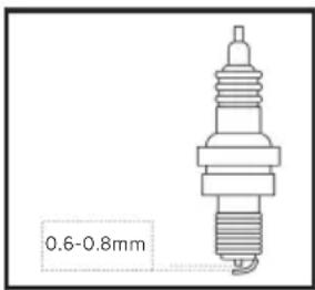
- Check the model of the spark plug and that it has sufficient clearance. If required, correct the gap.
Standard spark plug: A5RTC
Spark plug clearance: 0.6–0.8 mm
Tips: The engine may be damaged if the spark plug is not at the correct clearance height.
- Reinstall the spark plug with a torque of 13.5 ± 1.5 Nm.
Tip: If installing without a torque wrench, a good method is to tighten until tight, then continue to turn by a further 1/4-1/2 rotation.
-
Reinstall the spark plug cap on the spark plug.
-
Reinstall the maintenance cover.
3.2 Adjusting the Carburetor
The carburetor is an important part of engine, and should be adjusted by the dealer who has the professional knowledge, data and equipment to ensure it is adjusted correctly.
Usage in high altitude areas
In high altitude areas, the atmospheric pressure may reduce the amount of air intake, decline the performance and increase the fuel consumption of standard carburetors. Moreover, the dense mixture may contaminate the spark plug and lead to starting difficulties. When the generator is running at high altitudes (above 3000 feet/914 m), the emissions may increase.
Modifying the carburetor can improve its high altitude performance. If you plan to operate your generator at high altitude (above 3000 feet/914 m) areas for a long time, please contact your after-sales service team to help to modify it. When using the modified carburetor in high altitude areas (if within the service life of the generator), the generator will satisfy every emission standard.
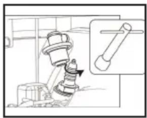
natural_image
Technical line drawing of a mechanical assembly with a magnified inset showing a cylindrical component (no text or symbols)Removing the spark plug
text_image
0.6-0.8mmSpark plug clearance
3.3 Replacing the Engine Oil
Warning
Do not drain the engine oil immediately after the generator is switched off. The oil temperature will be very high. Please take care not to get scalded when draining the oil.
- Place the generator on a level plane, start it up and keep it running for several minutes to increase its temperature. Then turn it off. Turn the Engine Switch and the fuel cap breather knob to "OFF".
- Turn the maintain cover knob to ☐ and take off the maintenance cover.
- Unscrew the lid and oil dipstick.
- Place the oil basin under the generator and tilt the generator. The oil will drain quickly.
Tips: Improper disposal of engine oil may harm the environment. If you replace the engine oil yourself, please dispose of the used oil properly. Store the used oil in a sealed container and take it to your nearest oil recycling center. Do not pour it into any trash can, onto the ground or into the sewer.
- Place the generator in its original horizontal state.
Caution
Do not tilt the generator when adding engine oil to prevent damage to the generator due to adding excessive oil.
- Refill the oil to the proper level.
- Wipe the oil dipstick clean and remove any spilled oil.
Warning
Prevent any foreign objects from entering the inside of the engine.
- Tighten the oil dipstick and lid.
- Reinstall the maintenance cover and turn the knob to Closed.
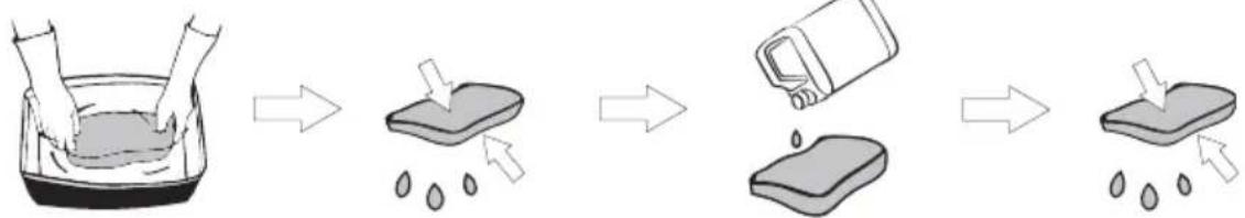
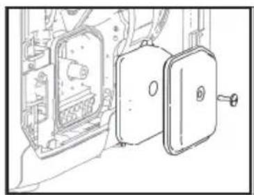
3.4 Air Filter
- Turn the maintain cover knob to 📋 and take off the maintenance cover.
- Take off the screws and the air filter cover.
- Take off the foam filter element.
- Clean the foam filter element with soapy water or a nonflammable solvent and dry it.
- Add oil to the foam filter element and squeeze out the excess oil. The foam filter element should be wet but should not drip any oil.
- Place the foam filter element into the air filter.
Tips: 1. Make sure that the surface of the foam filter element is in close contact with the air filter, leaving no gap between them.
-
Do not start the generator before reinstalling the air filter as excessive toxic gas may be produced and foreign objects may enter the engine, causing wear to the engine block.
-
Install the air filter cover back to its original position and tighten the screws.
- Reinstall the maintenance cover and turn the knob to Closed.
Caution
Do not twist the foam filter element, to prevent any damage to it.
flowchart
graph LR
    A["Person washing in a basin"] --> B["Add water droplets"]
    B --> C["Clean water droplets"]
    C --> D["Divine after washing"]
    D --> E["Clean water droplets"]
Wash clean Press and air dry (do not twist)
amount of oil
natural_image
Technical line drawing of a mechanical assembly with internal components and a door (no text or symbols)Removing the air filter cover
Press (do not twist)Add correct
3.5 Fuel Filter Strainer
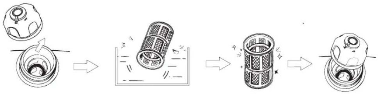
-
Take off the fuel cap and fuel filter screen.
-
Clean the fuel filter screen with fuel.
-
Wipe the filter screen and place it back into the fuel.
-
Reinstall the fuel cap.
Warning
Never use fuel in any place near smoke or flames.
Caution
Be sure to tighten the fuel cap.
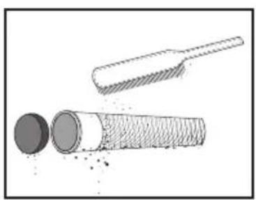
3.6 Muffler
- Unscrew the bolts.
- Take off the muffler cap, muffler block and spark plug arrestor.
- Clean the carbon deposits on the muffler block and the spark plug arrestor gently with a steel wire brush to avoid any damage or scratches to the muffler block and spark plug collector.
- Check whether the muffler block or the spark plug arrestor is damaged, and replace it if damaged.
- Reinstall the parts in turn.
natural_image
Illustration of a cylindrical object with a textured base and a broken handle, showing internal structure (no text or symbols)Clean any carbon deposits
Warning
Once the generator starts running, the engine and the muffler will become scalding hot. Do not let your skin or clothes directly touch the engine or muffler during your checks and maintenance.
4. Storage and Transportation
If you plan to place this generator into long-term storage, you need to take some storage measures to prevent premature aging of the generator.
4.1 Draining the Fuel
- Turn the Engine Switch to "OFF".
- Open the fuel cap, take out the fuel filter screen, drain all the fuel from the fuel tank into a temporary fuel tank and reinstall the fuel cap.
- Start the generator. The remaining fuel will be used up in about 20 minutes. The generator will turn off when there is no fuel left.
- Do not connect any electrical equipment to the generator.
- The time it takes for the generator to run depends on the remaining amount of fuel inside the fuel tank.
- Turn the maintain cover knob to ☐ and take off the maintenance cover.
- Loosen and remove the oil drain bolt on the carburetor and drain the fuel from the carburetor into the temporary fuel tank.
- Turn the Engine Switch to "OFF".
- Screw in and tighten the oil drain bolt.
- Reinstall the maintenance cover and turn the knob to Closed.
- Turn off the fuel cap breather valve knob after the engine cools down completely.
Warning
As fuel is highly volatile and toxic, please carefully read the "Safety Guidelines" for handling instructions.
Caution
Wipe any spilled fuel away with a clean soft cloth to prevent it from damaging the plastic shell.
4.2 Storing the Generator
Take the following steps to protect parts such as the engine body and piston rings which are the most susceptible to corrosion.
- Take out the spark plug, inject 10 mL/0.34 oz. of engine oil, reinstall the spark plug, and pull the Starter Grip for several minutes so that the engine oil can fully lubricate the cylinder block.
- Pull the Starter Grip until it becomes tight (to prevent the cylinder block and valves rusting).
- Wipe the generator's surface clean, place the generator in a well-ventilated and dry place and cover it.
4.3 Rechargeable Battery
Disconnect the battery each time you store it for a longer period of time and reconnect it before using it again.
Attention: The battery should be charged and discharged once every 3 months. It will charge while the engine is running.
4.4 Use after storage
If the generator is stored with fuel in the fuel tank and carburetor, conduct servicing as required in the table below before using again.
| Storage Duration | Recommended Servicing Procedure to Prevent Difficult Startups |
| Within one month | No preparation needed |
| One to two months | Evacuate the fuel and inject fresh fuel |
| Two months to one year | Evacuate the fuel and inject fresh fuel |
| Drain the fuel from Carburetor Drain Cup 1 | |
| Drain the fuel from Sediment Bowl 2 | |
| Over one year | Evacuate the fuel and inject fresh fuel |
| Drain the fuel from Carburetor Drain Cup 1 | |
| Drain the fuel from Sediment Bowl 2 | |
| Drain the original fuel into a suitable storage container after moving it out of storage and inject fresh fuel before starting it. | |
| 1Loosen and remove the oil drain bolt and drain all the fuel out of the carburetor. Drain the fuel into a suitable container, and screw in and tighten the oil drain bolt.2After turning off the Engine Switch, remove the Sediment Bowl, empty the gasoline from the bowl, reinstall the Sediment Bowl and tighten it. | |
4.5 Transportation
Caution
- When moving, storing or operating the generator, do not place it on its side. The engine oil may leak and damage the engine or your property.
- If the generator is constantly running, allow it to cool before being loaded onto the transport vehicle. Hot engines and waste systems may cause burns and can cause certain materials to ignite. To prevent fuel spills during transport, position the generator vertically in the standard operating position, and turn the engine switch and the fuel cap breather valve knob to the “OFF” position.
- During transportation, take care not to let the generator fall or be impacted.
5. Faults and Troubleshooting
Eros Current of Type Tumor Type Protective Cases Recovery Methods
| In millions | The end of the last two blocks in the Oil platform | The end of the last two blocks in the Oil Platform | ||
| The Engle Sable to the Oil Platform. There is the Engle Sable to "CON" | ||||
| Total to the Oil Platform | ||||
| Fuel system | The power or fuel system property provided for strength, in the gas flow and water associated, or the quality of equipment found more | |||
| Under- to end | Oil Alert between ways on | Endline oil system | The following record: Customer index, leader, faller, or stock prices, etc. | The generation power has been used to operate in the Service Network |
| Low energy still present. The energy still system may be used for the engine. | All engine oil | |||
| The gas price is slightly above the input output data. | After the consumption is replaced by the pack. | |||
| Oil Alert between ways on | Electrical system | The quick play has been standardised by the input provided in the engine; | Pays the gas play with an underground level. | |
| Continuous failure | and the generation power has been used to operate in the Service Network | |||
| Line steps on | Lack of battery power or the heater is damaged | Fully used to operate in the battery | ||
| Line steps on | 1. Descriptive specified order values | Per unitisation | Turn off the generation and approve the system | |
| Air flows | AC access provision for closed problems | Reserves the solution and use low and moderate | ||
| No side | Air flows | DC installed portion load closed problem | Reserves the solution and use low and moderate | |
| Extra volumes on | Cross-over-greational protection | The manufacturers' current system supports the high capacity of the fuel tank knowledge | Check the entire government that the high capacity of the government is reduced by the load | |
| Extra volumes on | Barry over large units | The non-ablersional system supports the high capacity of the fuel tank knowledge | Check the entire government that the high capacity of the government is reduced by the load | |
Communication failure: Communication failures may occur in two specific situations, as detailed below.
1) Normal failure: When the generator is connected to DELTA Max or DELTA Pro, if the generator goes
into sleep mode, a communication failure will occur. In this situation, press a button to activate the
generator and the communication failure will disappear.
2) Abnormal failure: If the communication failure does not disappear once the generator has been
activated or while the generator is running, this could indicate that the failure has been caused by a
problem with the generator.
If any alert occurs during the use of this product and if the alert icon does not disappear after the
foregoing methods are attempted or the product is restarted, please stop using it immediately.
If the above information still fails to solve your problem, please contact our professional service
personnel for further support.
6. Parameters and Specifications
| Complete machine | Length × width × height 23.5×11.7×18.7 in/597×296×475 mm | |
| Net weight 64.6 lbs/29.3 kg | ||
| Generator | Type Inverter generator | |
| Frequency 50 Hz | ||
| Rated voltage 230 V | ||
| Rated power 1800 W (peak value 1900 W) | ||
| Power factor 1 | ||
| DC output voltage 42-58.8 V | ||
| Maximum DC output current 32 A | ||
| Engine | Engine model | R80-i |
| Engine type | Single cylinder, four-stroke, forced-air cooling, overhead valve | |
| Engine displacement | 79.7 CC | |
| Type of fuel | Unleaded fuel | |
| Volume of fuel tank | 1.06 gal./4 L | |
| Generator engine oil volume | 0.1 gal./ 0.38 L | |
| Continuous Working Time | 3.5 Hr (full load) | |
| Noise Level (at a distance of 7 meters) | 56-67 dB (full load) | |
| Model of spark plug | A5RTC (TORCH) | |
| Start mode | Electric start | |
7. Package List
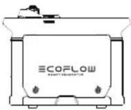
natural_image
Line drawing of a container with 'ECOFLOW' branding and mounting holes (no text or symbols beyond branding)Smart Generator
User Manual and Warranty Card
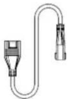
Extra Battery
Connection Cable
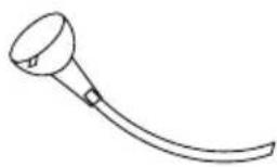
natural_image
Simple line drawing of a curved tool or device with a handle and circular head (no text or symbols)Oil Funnel

Screwdriver

Spark Plug Socket Breaker Bar
Double-Ended Spanner
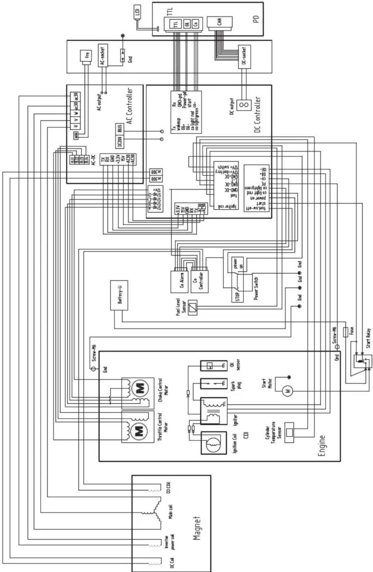
8. Circuit Diagram
flowchart
graph TD
    subgraph Magnet
        A["DC Coil"] --> B["Inverter power coil"]
        B --> C["Main coil"]
        C --> D["CO COI"]
        E["Ignition Coil"] --> F["Igniter CDI"]
        G["Cylinder Temperature Sensor"] --> H["Start Motor"]
        I["Screw-M6"] --> J["Throttle Control Motor"]
        K["Choke Control Motor"] --> L["Spark plug"]
        M["Oil sensor"] --> N["Co Controller"]
        O["Engine"] --> P["Fuse"]
        Q["Start Relay"] --> R["Screw-M6"]
    end

    subgraph AC Controller
        S["Battery-Li"] --> T["Co Alarms"]
        T --> U["Co Controller"]
        V["AC-DC"] --> W["TX RX GND +3.3V ISV AC30 +AC30"]
        X["AC-DC"] --> Y["AC200"]
        Z["AC-DC"] --> AA["AC200"]
        AB["AC-DC"] --> AC["AC200"]
        AD["AC-DC"] --> AE["AC200"]
        AF["AC-DC"] --> AG["AC200"]
        AH["AC-DC"] --> AI["AC200"]
        AJ["AC-DC"] --> AK["AC200"]
        AL["AC-DC"] --> AM["AC200"]
        AN["AC-DC"] --> AO["AC200"]
        AP["AC-DC"] --> AQ["AC200"]
        AR["AC-DC"] --> AS["AC200"]
        AT["AC-DC"] --> AU["AC200"]
        AV["AC-DC"] --> AW["AC200"]
        AX["AC-DC"] --> AY["AC200"]
        AZ["AC-DC"] --> BA["AC200"]
        BB["AC-DC"] --> BC["AC200"]
        BD["AC-DC"] --> BE["AC200"]
        BF["AC-DC"] --> BG["AC200"]
        BH["AC-DC"] --> BI["AC200"]
        BJ["AC-DC"] --> BK["AC200"]
        BL["AC-DC"] --> BM["AC200"]
        BN["AC-DC"] --> BO["AC200"]
        BP["AC-DC"] --> BQ["GND-pd Power-pd start co-a lightgreen"]
        BP --> BR["GND-pd Power-pd start co-a lightgreen"]
        BS["TX wakeup 0A+ 0B+ co light red co lightgreen"]
        BT["Rx wakeup 0A+ 0B+ co light red co lightgreen"]
        BU["GND-pd Power-pd start co-a lightgreen"]
        BV["TX wakeup 0A+ 0B+ co light red co lightgreen"]
        BW["GND-pd Power-pd start co-a lightgreen"]
        BX["GND-pd Power-pd start co-a lightgreen"]
    end

    subgraph PD
        BY["TTL TTL 0A Co CAN"]
    end

    A --> M
    E --> N
    G --> O
    I --> P
    M --> Q
    N --> R
    O --> S
    P --> T
    Q --> U
    R --> V
    S --> W
    T --> X
    U --> Y
    V --> Z
    W --> AA
    X --> AB
    Y --> AC
    Z --> AD
    AA --> AE
    AB --> AF
    AC --> AG
    AD --> AH
    AE --> AI
    AF --> AJ
    AG --> AK
    AH --> AL
    AI --> AM
    AJ --> AN
    AK --> AO
    AL --> AP
    AM --> AQ
    AN --> AR
    AO --> AS
    AP --> AT
    AQ --> AU
    AR --> AV
    AS --> AW
    AT --> AX
    AU --> AY
    AV --> AZ
    AW --> BA
    AX --> BB
    AY --> BC
    AZ --> BD
    BA --> BE
    BB --> BF
    AC --> BG
    AD --> BH
    AE --> BI
    AF --> BJ
    AG --> BK
    AH --> BL
    AI --> BM
    AJ --> BN
    AK --> BO
    AL --> BP
    AM --> BR
    AN --> CA
    AO --> CB
    AP --> CC
    AQ --> CD
    AS --> CE
    AT --> CF
    AU --> CG
    AV --> CH
    AW --> CI
    AX --> CJ
    AY --> CK
    AZ --> CL
    BA --> CM
    AC --> CN
    AD --> CO
    AE --> CP
    AF --> CO
    AG --> CR
    AH --> CS
    AI --> CS
    AJ --> CS
    AK --> CS
    AL --> CS
    AM --> CS
    AN --> CS
    AO --> CS
    AP --> CS
    AQ --> CS
    AS --> CS
    AT --> CS
    AU --> CS
    AV --> CS
    AW --> CS
    AX --> CS
    AY --> CS
    AZ --> CS
    AO --> CS
    AP --> CS
    AQ --> CS
    AS --> CS

    subgraph Control Components
        T1["TX RX GND +3.3V ISV AC30 +AC30"]
        T2["TX wakeup 0A+ 0B+ co light red co lightgreen"]
        T3["TX wakeup 0A+ 0B+ co light red co lightgreen"]
        T4["TX wakeup 0A+ 0B+ co light red co lightgreen"]
        T5["TX wakeup 0A+ 0B+ co light red co lightgreen"]
        T6["TX wakeup 0A+ 0B+ co light red co lightgreen"]
        T7["TX wakeup 0A+ 0B+ co light red co lightgreen"]
        T8["TX wakeup 0A+ 0B+ co light red co lightgreen"]
        T9["TX wakeup 0A+ 0B+ co light red co lightgreen"]
        T10["TX wakeup 0A+ 0B+ co light red co lightgreen"]
        T11["TX wakeup 0A+ 0B+ co light red co lightgreen"]
        T12["TX wakeup 0A+ 0B+ co light red co lightgreen"]
        T13["TX wakeup 0A+ 0B+ co light red co lightgreen"]
        T14["TX wakeup 0A+ 0B+ co light red co lightgreen"]
        T15["TX wakeup 0A+ 0B+ co light red co lightgreen"]
        T16["TX wakeup 0A+ 0B+ co light red co lightgreen"]
        T17["TX wakeup 0A+ 0B+ co light red co lightgreen"]
        T18["TX wakeup 0A+ 0B+ co light red co lightgreen"]
        T19["TX wakeup 0A+ 0B+ co light red co lightgreen"]
        T20["TX wakeup 0A+ 0B+ co light red co lightgreen"]
        T21["TX wakeup 0A+ 0B+ co light red co lightgreen"]
        T22["TX wakeup 0A+ 0B+ co light red co lightgreen"]
        T23["TX wakeup 0A+ 0B+ co light red co lightgreen"]
        T24["TX wakeup 0A+ 0B+ co light red co lightgreen"]
        T25["TX wakeup 0A+ 0B+ co light red co lightgreen"]
        T26["TX wakeup 0A+ 0B+ co light red co lightgreen"]
        T27["TX wakeup 0A+ 0B+ co light red co lightgreen"]
        T28["TX wakeup 0A+ 0B+ co light red co lightgreen"]
        T29["TX wakeup 0A+ 0B+ co light red co lightgreen"]
        T30["TX wakeup 0A+ 0B+ co light red co lightgreen"]
        T31["TX wakeup 0A+ 0B+ co light red co lightgreen"]
        T32["TX wakeup 0A+ 0B+ co light red co lightgreen"]
        T33["TX wakeup 0A+ 0B+ co light red co lightgreen"]
        T34["TX wakeup 0A+ 0B+ co light red co lightgreen"]
        T35["TX wakeup 0A+ 0B+ co light red co lightgreen"]
        T36["TX wakeup 0A+ 0B+ co light red co lightgreen"]
        T37["TX wakeup 0A+ 0B+ co light red co lightgreen"]
        T38["TX wakeup 0A+ 0B+ co light red co lightgreen"]
        T39["TX wakeup 0A+ 0B+ co light red co lightgreen"]
        T40["TX wakeup 0A+ 0B+ co light red co lightgreen"]
        T41["TX wakeup 0A+ 0B+ co light red co lightgreen"]
        T42["TX wakeup 0A+ 0B+ co light red co lightgreen"]
        T43["TX wakeup 0A+ 0B+ co light red co lightgreen"]
        T44["TX wakeup 0A+ 0B+ co light red co lightgreen"]
        T45["TX wakeup 0A+ 0B+ co light red co lightgreen"]
        T46["TX wakeup 0A+ 0B+ co light red co lightgreen"]
        T47["TX wakeup 0A+ 0B+ co light red co lightgreen"]
        T48["TX wakeup 0A+ 0B+ co light red co lightgreen"]
        T49["TX wakeup 0A+ 0B+ co light red co lightgreen"]
        T51["TX wakeup"] & TC1/TTC/TTL/CA/CO/AN/PD/PD/PD/PD/PD/PD/PD/PD/PD/PD/PD/PD/PD/PD/PD/PD/PD/PD/PD/PD/PD/PD/PD/PD/PD/PD/PD/PD/PD/PD/PD/PD/PD/PD/PD/PD/PD/PD/PD/PD/PD/PD/PD/PD/PD/PD/PD/PD/PD/PD/Pd/Pd/Pd/Pd/Pd/Pd/Pd/Pd/Pd/Pd/Pd/Pd/Pd/Pd/Pd/Pd/Pd/Pd/Pd/Pd/Pd/Pd/Pd/Pd/Pd/Pd/Pd/Pd/Pd/Pd/Pd/Pd/Pd/Pd/Pd/Pd/Pd/Pd/Pd/Pd/Pd/Pd/Pd/Pd/Pd/Pd/Pd/Pd/Pd/Pd/PD/Pd/Pd/Pd/Pd/Pd/Pd/Pd/Pd/Pd/Pd/Pd/Pd/Pd/Pd/Pd/Pd/Pd/Pd/Pd/Pd/Pd/Pd/Pd/Pd/Pd/Pd/Pd/Pd/Pd/Pd/Pd/Pd/Pd/Pd/Pd/Pd / PC1 / PC2 / PC3 / PC4 / PC5 / PC6 / PC7 / PC8 / PC9 / PC10 / PC11 / PC12 / PC13 / PC14 / PC15 / PC16 / PC17 / PC18 / PC19 / PC20 / PC21 / PC22 / PC23 / PC24 / PC25 / PC26 / PC27 / PC28 / PC29 / PC30 / PC31 / PC32 / PC33 / PC34 / PC35 / PC36 / PC37 / PC38 / PC39 / PC40 / PC41 / PC42 / PC43 / PC44 / PC45 / PC46 / PC47 / PC48 / PC49 / PC50 / PC51 / PC52 / PC53 / PC54 / PC55 / PC56 / PC57 / PC58 / PC59 / PC60 / PC61 / PC62 / PC63 / PC64 / PC65 / PC66 / PC67 / PC68 / PC69 / PC70 / PC71 / PC72 / PC73 / PC74 / PC75 / PC76 / PC77 / PC78 / PC79 / PC80 / PC81 / PC82 / PC83 / PC84 / PC85 / PC86 / PC87 / PC88 / PC89 / PC90 / PC91 / PC92 / PC93 / PC94 / PC95 / PC96 / PC97 / PC98 / PC99 / DC output: DC socket: DC socket: DC socket: DC socket: DC socket: DC socket: DC socket: DC socket: DC socket: DC socket: DC socket: DC socket: DC socket: DC socket: DC socket: DC socket: DC socket: DC socket: DC socket: DC socket: DC socket: DC socket: DC socket: DC socket: DC socket: DC socket: DC socket: DC socket: DC socket: DC socket: DC socket: DC socket: DC socket: DC socket:PDP
ECOFLOW
text_image
ECOFLOW SMART GENERATORHaftungsausschluss
natural_image
Diagram of a ceiling structure with an X-shaped panel and a cabinet, showing no text or symbols.natural_image
Diagram of a mechanical device with intersecting bands and an umbrella, no text or symbols presentnatural_image
Diagram of a mechanical device with two crossed bands and a central component (no text or symbols)text_image
Diagram illustrating a mechanical or electrical hazard with labeled components and distance measurement '>1m'natural_image
Diagram showing a hand holding a pen and a box on a cross-shaped background (no text or symbols)natural_image
Diagram of a device with two crossed bands and a lightning bolt symbol (no text or labels)natural_image
Diagram of a mechanical component with an arrow indicating rotational motion (no text or symbols)text_image
Technical diagram showing a device with internal components and a labeled 'ECOPLOM' component, alongside a circular icon with directional arrows.natural_image
Line drawing of a car engine compartment with a funnel and water drop, no text or symbols presentnatural_image
Technical line drawing of a mechanical assembly with an inset showing a connector detail (no text or symbols)natural_image
Illustration of a bottle being poured into a container with an arrow indicating liquid level (no text or symbols)text_image
Line drawing showing hands using a device labeled 'BCORCLON' to interact with a water pump, indicating a process or operation.Manueller Start
b) Manueller Start
text_image
QR code image containing encoded data, no visible human-readable textnatural_image
Technical line drawing of a mechanical assembly with a magnified inset showing a cylindrical component (no text or symbols)natural_image
Technical line drawing of a mechanical assembly with two components (no text or symbols)natural_image
Illustration of a cylindrical object with a circular cap and a textured base, alongside a pair of tools (no text or symbols)natural_image
Line drawing of a container with 'ECOFLOW' branding and mounting holes (no text or symbols beyond branding)Smart Generator
natural_image
Simple line drawing of a curved tool or device with a circular head and handle (no text or symbols)Öltrichter

Schraubendreher
text_image
ECOFLOW SMART GENERATORnatural_image
Diagram showing a window with a door and a window with curtains, enclosed in a dashed border (no text or symbols)natural_image
Diagram of a mechanical assembly with intersecting bands and a central component (no text or symbols)natural_image
Diagram of a mechanical device with two crossed bands and a central component (no text or symbols)text_image
Diagram illustrating a mechanical assembly or processing process with labeled components and distance annotation '>1m'text_image
Diagram showing a hand holding a pen and a device crossed out by two crossed bands, indicating safety or hazard zones.natural_image
Cross-shaped diagram with a battery box and lightning bolt symbol (no text or labels)| WARNING Read the owner's manual and all labels before operating. | ||
| Only operate in well-ventilated areas. Using a generator indoors CAN KILL YOU IN MINUTES. Generator exhaust contains carbon monoxide. This is a poison you cannot see or smell. Tampering with this CO alarm system will cause Carbon Monoxide poisoning! | ||
| Electrocution can occur if generator is used in rain, snow, or near water. Keep this unit dry at all times. Electrocution or property damage can occur. Refer to the owner's manual. | Backfeed into utility system can cause property damage and electrocution hazard. Do not connect the generator to a building's electrical system unless an isolation switch has been properly installed by a licensed electrician. | |
| Check for spilled fuel or fuel leaks. Stop engine before refueling. Do not operate near flammable materials. | ||
| When operating the generator: Never place a partition or other barrier around the generator. Do not cover the generator with a box. Do not place any objects on the generator. Turn the fuel tank cap air vent knob to "OFF" after the engine has completely cooled down. | ||
text_image
Low power generating sets MODEL: EFG100 WEIGHT: 29.3kg MAXIMUM POWER: MAX 1900W RATED FREQUENCY: 50 Hz RATED POWER(AC+DC total): COP.1800W PERFORMANCE CLASS: GI RATED VOLTAGE: 230V QUALITY CLASS: Class A RATED CURRENT: 7.8A YEAR OF CONSTRUCTION: 2021 DC OUTPUT: 58.8V, 32A DEGREE OF PROTECTION: IP23M RATED POWER FACTOR: Factory Building A202, Founder Technology Industrial Park, North Side of Songbai Highway, Longteng Community, Shiyan Sub-district, Baoan District, Shenzhen City, Guangdong, China MADE IN CHINA: EcoFlow Inc. www.ecoflow.com
text_image
WARNING Operation of this equipment may create sparks that can start fires around dry vegetation. A spark arrestor may be required, The operator should contact local fire agencies for laws or regulations relating to fire prevention requirements. Hot exhaust can bum you. Stay away if engine has been running. ↓ ECORLOW2. Démarrage rapide
natural_image
Diagram of a mechanical component with an arrow indicating rotational motion (no text or symbols)natural_image
Line drawing of a device casing with internal components and a circular inset showing a rotary switch (no text or symbols)natural_image
Line drawing of a mechanical device with a funnel and pouring liquid, no text or symbols presentnatural_image
Technical line drawing of a mechanical component with an inset magnified detail (no text or symbols)natural_image
Illustration of a bottle being poured into a container with an arrow indicating liquid level (no text or symbols)text_image
QR code image containing encoded data, no visible human-readable textnatural_image
Technical line drawing of a mechanical assembly with a magnified inset showing a cylindrical component (no text or symbols)natural_image
Technical line drawing of a mechanical assembly with two rectangular components and internal components (no text or symbols)flowchart
graph LR
    A["Water washing"] --> B["Water bath"]
    B --> C["Water droplet"]
    C --> D["Water container with drop"]
    D --> E["Water surface with droplets"]
natural_image
Illustration of a cylindrical object with a textured base and a separate cylindrical tool inserted into it (no text or symbols)4.3 Batterie rechargeable
natural_image
Line drawing of a EcoFlow container with control panel (no text or symbols)Smart Generator
text_image
ECOFLOW SMART GENERATORnatural_image
Diagram showing a window with a door and a window with curtains, no text or symbols presentnatural_image
Diagram of a mechanical assembly with intersecting bands and an umbrella (no text or symbols)natural_image
Diagram of a battery with two crossed bands and a clamped tag, no text or symbols presenttext_image
Diagram showing a machine with gear and a container, annotated with distance '1m' and directional arrowstext_image
Diagram showing a hand pointing at a device against a cross-shaped barrier, with no text or symbols present.natural_image
Diagram of a device with two crossed bands and a lightning bolt symbol, no text or labels present| WARNING | ||
| Read the owner's manual and all labels before operating. | ||
| Only operate in well-ventilated areas. Using a generator indoors CAN KILL YOU IN MINUTES Generator exhaust contains carbon monoxide. This is a poison you cannot see or smell. Tampering with this CO alarm system will cause Carbon Monoxide poisoning! | ||
| Electrocution can occur if generator is used in rain, snow, or near water. Keep this unit dry at all times. Electrocution or property damage can occur. Refer to the owner's manual. | Backfeed into utility system can cause property damage and electrocution hazard. Do not connect the generator to a building's electrical system unless an isolation switch has been properly installed by a licensed electrician. | |
| Check for spilled fuel or fuel leaks. Stop engine before refueling. Do not operate near flammable materials. | ||
| When operating the generator: Never place a partition or other barrier around the generator. Do not cover the generator with a box. Do not place any objects on the generator. Turn the fuel tank cap air vent knob to "OFF" after the engine has completely cooled down. | ||

text_image
Low power generating sets MODEL: EFG100 WEIGHT: 29.3kg MAXIMUM POWER: MAX 1900W RATED FREQUENCY: 50 Hz RATED POWER(AC+DC total): COP.1800W PERFORMANCE CLASS: CI RATED VOLTAGE: 230V QUALITY CLASS: Class A RATED CURRENT: 7.8A YEAR OF CONSTRUCTION: 2021 DC OUTPUT: 58.8V, 32A DEGREE OF PROTECTION: IP23M RATED POWER FACTOR: 1 Factory Building A202, Founder Technology Industrial Park, North Side of Songbai Highway, Longtong Community, Shiyan Sub-district, Baoan District, Shenzhen City, Guangdong, China MADE IN CHINA EcoFlow Inc. www.ecoflow.com
text_image
WARNING Operation of this equipment may create sparks that can start fires around dry vegetation. A spark arrestor may be required, The operator should contact local fire agencies for laws or regulations relating to fire prevention requirements. Hot exhaust can bum you. Stay away if engine has been running. ↓ ECORLOW2. Avvio rapido
natural_image
Diagram of a mechanical component with an arrow indicating rotational motion (no text or symbols)text_image
Diagram showing a device with a labeled 'SCOPLOM' and a circular icon with an arrow, indicating a process or operation.natural_image
Line drawing of a mechanical device with a funnel and drop funnel, no text or symbols presentnatural_image
Technical line drawing of a mechanical component with an inset magnified view of its connector detail (no text or symbols)natural_image
Illustration of a bottle being poured into a container with an arrow indicating liquid level (no text or symbols)text_image
Diagram showing hand holding a device with Chinese text, likely indicating a device's status or operation.Avviamento manuale
text_image
QR code image containing encoded data, no visible human-readable textCandela standard: A5RTC
natural_image
Technical line drawing of a mechanical assembly with a magnified inset showing a cylindrical component (no text or symbols)natural_image
Technical line drawing of a mechanical assembly with two rectangular components and internal components (no text or symbols)natural_image
Illustration of a cylindrical object with a textured base and a separate cylindrical object with a handle, showing no text or symbols.natural_image
Line drawing of a EcoFlow container with control panel (no text or symbols)Smart Generator
text_image
ECOFLOW SMART GENERATORnatural_image
Diagram of a cross-shaped structure with internal components and an inset showing a window (no text or symbols)natural_image
Diagram of a device with an umbrella and two crossed bands, no text or symbols presentnatural_image
Diagram of a battery with two crossed bands, no text or symbols presenttext_image
Diagram showing a cross-shaped barrier with a hand holding a tool, alongside a box labeled '安全带' (safety belt).natural_image
Diagram of a device with two crossed bands and a lightning bolt, no text or symbols present| WARNING | ||
| Read the owner's manual and all labels before operating. | ||
| Only operate in well-ventilated areas. Using a generator indoors CAN KILL YOU IN MINUTES Generator exhaust contains carbon monoxide. This is a poison you cannot see or smell. Tampering with this CO alarm system will cause Carbon Monoxide poisoning! | ||
| Electrocution can occur if generator is used in rain, snow, or near water. Keep this unit dry at all times. Electrocution or property damage can occur. Refer to the owner's manual. | Backfeed into utility system can cause property damage and electrocution hazard. Do not connect the generator to a building's electrical system unless an isolation switch has been properly installed by a licensed electrician. | |
| Check for spilled fuel or fuel leaks. Stop engine before refueling. Do not operate near flammable materials. | ||
| When operating the generator: Never place a partition or other barrier around the generator. Do not cover the generator with a box. Do not place any objects on the generator. Turn the fuel tank cap air vent knob to "OFF" after the engine has completely cooled down. | ||

text_image
Low power generating sets MODEL: EFG100 WEIGHT: 29.3kg MAXIMUM POWER: MAX 1900W RATED FREQUENCY: 50 Hz RATED POWER(AC+DC total): COP.1800W PERFORMANCE CLASS: CI RATED VOLTAGE: 230V QUALITY CLASS: Class A RATED CURRENT: 7.8A YEAR OF CONSTRUCTION: 2021 DC OUTPUT: 58.8V, 32A DEGREE OF PROTECTION: IP23M RATED POWER FACTOR: 1 Factory Building A202, Founder Technology Industrial Park; North Side of Songbai Highway, Longtong Community, Shiyan Sub-district, Baoan District, Shenzhen City, Guangdong, China MADE IN CHINA EcoFlow Inc. www.ecoflow.com
text_image
WARNING Operation of this equipment may create sparks that can start fires around dry vegetation. A spark arrestor may be required, The operator should contact local fire agencies for laws or regulations relating to fire prevention requirements. Hot exhaust can bum you. Stay away if engine has been running. ↓ ECORLOU2. Inicio rápido
natural_image
Diagram of a mechanical component with an arrow indicating rotational motion (no text or symbols)text_image
Diagram showing a device with internal components and a labeled 'SCOPLOM' logo, alongside a circular icon with directional arrows.natural_image
Line drawing of a car interior with a funnel, bucket, and spray bottle (no text or symbols)natural_image
Technical line drawing of a mechanical component with an inset magnified view of its connector detail (no text or symbols)natural_image
Illustration of a bottle being poured into a container with an arrow indicating liquid level (no text or symbols)text_image
Diagram showing hands operating a device labeled 'SCOLDA' with a control panel and indicator lightsArranque manual
b) Arranque manual
text_image
QR code image containing encoded data, no visible human-readable textnatural_image
Technical line drawing of a mechanical assembly with a magnified inset showing a cylindrical component (no text or symbols)natural_image
Technical line drawing of a mechanical assembly with internal components and a door handle (no text or symbols)natural_image
Illustration of a cylindrical tool with a circular base and a handle, showing mechanical components (no text or symbols)natural_image
Line drawing of a EcoFlow container with no visible text or symbolsGenerador inteligente Smart Generator
natural_image
Simple line drawing of a medical or laboratory instrument with a curved handle and circular top (no text or symbols)Embudo de aceite
Destornillador
text_image
ECOFLOW SMART GENERATORDisclaimer
natural_image
Diagram of a mechanical or electrical component with cross-shaped boundaries and internal structure, no visible text or symbolstext_image
Diagram illustrating a physical setup with labeled components and distance measurement, showing a container with fuel and a cylinder.natural_image
Diagram of a satellite or spacecraft with intersecting beams and an umbrella, no text or symbols presenttext_image
Diagram showing a hand holding a pen and a box on a cross-shaped barrier, with no text or symbols present.natural_image
Diagram of a device with two crossed bands and a rectangular box, no text or symbols presentnatural_image
Diagram of a mechanical device with two crossed bands and a hanging part, no text or symbols present| WARNING | ||
| Read the owner's manual and all labels before operating. | ||
| Only operate in well-ventilated areas. Using a generator indoors CAN KILL YOU IN MINUTES Generator exhaust contains carbon monoxide. This is a poison you cannot see or smell. Tampering with this CO alarm system will cause Carbon Monoxide poisoning! | ||
| Electrocution can occur if generator is used in rain, snow, or near water. Keep this unit dry at all times. Electrocution or property damage can occur. Refer to the owner's manual. | Backfeed into utility system can cause property damage and electrocution hazard. Do not connect the generator to a building's electrical system unless an isolation switch has been properly installed by a licensed electrician. | |
| Check for spilled fuel or fuel leaks. Stop engine before refueling. Do not operate near flammable materials. | ||
| When operating the generator: Never place a partition or other barrier around the generator. Do not cover the generator with a box. Do not place any objects on the generator. Turn the fuel tank cap air vent knob to "OFF" after the engine has completely cooled down. | ||

text_image
Low power generating sets MODEL: EFG100 WEIGHT: 29.3kg MAXIMUM POWER: MAX 1900W RATED FREQUENCY: 50 Hz RATED POWER(AC+DC total): COP.1800W PERFORMANCE CLASS: CI RATED VOLTAGE: 230V QUALITY CLASS: Class A RATED CURRENT: 7.8A YEAR OF CONSTRUCTION: 2021 DC OUTPUT: 58.8V, 32A DEGREE OF PROTECTION: IP23M RATED POWER FACTOR: 1 Factory Building A202, Founder Technology Industrial Park; North Side of Songbai Highway, Longtong Community, Shiyan Sub-district, Baoan District, Shenzhen City, Guangdong, China MADE IN CHINA EcoFlow Inc. www.ecoflow.com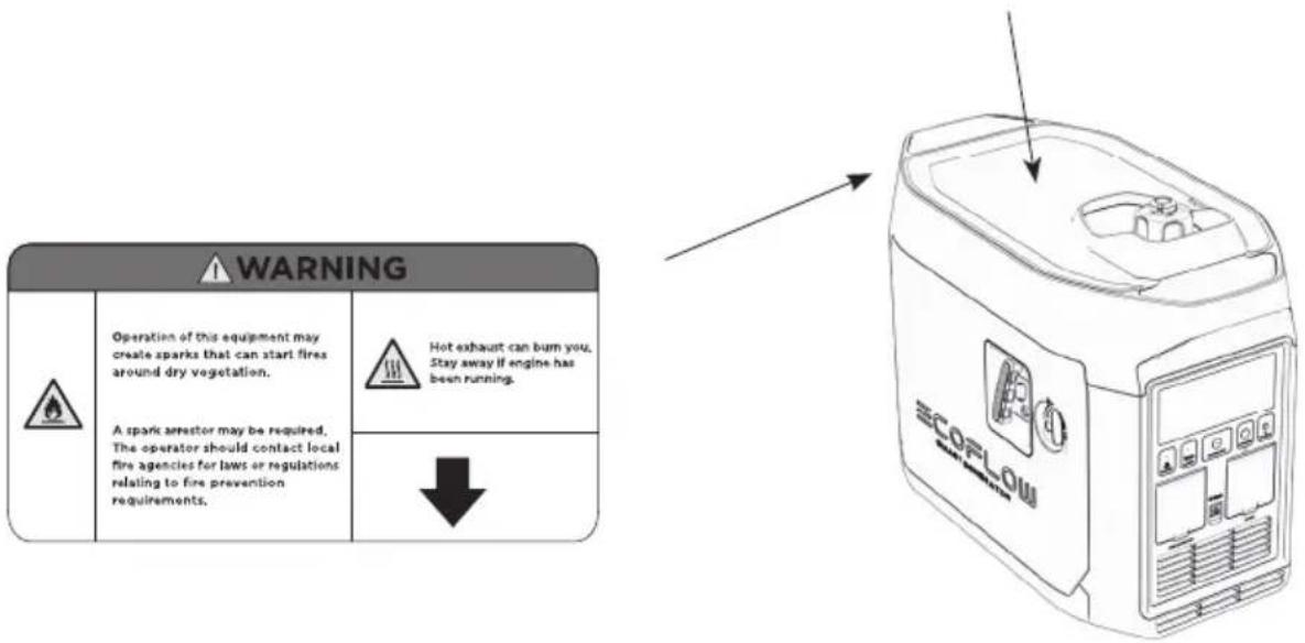
text_image
WARNING Operation of this equipment may create sparks that can start fires around dry vegetation. A spark arrestor may be required, The operator should contact local fire agencies for laws or regulations relating to fire prevention requirements. Hot exhaust can burn you, Stay away if engine has been running. ↓ ECORLOW2. Snel aan de slag
natural_image
Diagram of a mechanical component with an arrow indicating rotational motion (no text or symbols)text_image
Technical diagram showing a device with internal components and a labeled 'ECOPLOM' component, alongside a circular icon with directional arrows.natural_image
Line drawing of a car interior with a funnel, water drop, and plastic bottle (no text or symbols)Motorolie bijvullen
natural_image
Technical line drawing of a mechanical component with an inset magnified view of its connector detail (no text or symbols)natural_image
Illustration of a bottle being poured into a container with an arrow indicating liquid level (no text or symbols)text_image
QR code image containing encoded data, no visible human-readable text2.4.6 Toepassingsbereik
natural_image
Technical line drawing of a mechanical assembly with a magnified inset showing a cylindrical component (no text or symbols)natural_image
Technical line drawing of a mechanical assembly with internal components (no text or symbols)natural_image
Illustration of a cylindrical object with a textured base and a brush-like tool above it, no text or symbols present.natural_image
Line drawing of a container with 'ECOFLOW' branding and mounting holes (no text or symbols beyond branding)Smart Generator
natural_image
Simple line drawing of a curved tool or device with a circular head and handle (no text or symbols)Olietrechter

Schroevendraaier
flowchart
graph TD
    subgraph Magnet
        A["DC Coil"] --> B["Inverter power coil"]
        B --> C["Main coil"]
        C --> D["CO COI"]
    end

    subgraph Engine
        E["Ignition Coil"] --> F["Igniter CDI"]
        F --> G["Cylinder Temperature Sensor"]
        G --> H["Start Motor"]
        H --> I["Screw-M6"]
        I --> J["Fuse"]
        J --> K["Start Relay"]
    end

    subgraph Ac Controller
        L["Battery-Li"] --> M["Co Alarm"]
        M --> N["Co Controller"]
        N --> O["STOP"]
        O --> P["Power Switch"]
        P --> Q["+3.3V EV"]
        Q --> R["GND"]
        R --> S["RX TX +AC30"]
        S --> T["+3.3V +V battery + switch"]
        T --> U["Tax wakeup 01-02 co light red co lightgreen"]
        U --> V["Rx GN3-pd Power-pd start co lightgreen"]
        V --> W["DC output"]
        W --> X["DC-socket"]
    end

    subgraph PD
        Y["AC socket"] --> Z["Fre"]
        Z --> AA["AC output"]
        AA --> AB["DC200"]
        AB --> AC["BU5"]
        AC --> AD["AC-DC"]
        AD --> AE["AC-DC"]
        AE --> AF["AC-DC"]
        AF --> AG["AC-DC"]
        AG --> AH["AC-DC"]
        AH --> AI["AC-DC"]
        AI --> AJ["AC-DC"]
    end

    subgraph Control
        AK["Throttle Control Motor"] --> AL["Choke Control Motor"]
        AL --> AM["Screw-M6"]
    end

    subgraph Control
        AN["AC Controller"] --> AO["AC-DC"]
    end

    subgraph Control
        AP["AC-DC"] --> AQ["AC-DC"]
    end

    subgraph Control
        AR["AC-DC"] --> AS["AC-DC"]
    end

    subgraph Control
        AT["AC-DC"] --> AU["AC-DC"]
    end

    subgraph Control
        AV["AC-DC"] --> AW["AC-DC"]
    end

    subgraph Control
        AX["AC-DC"] --> AY["AC-DC"]
    end

    subgraph Control
        AZ["AC-DC"] --> BA["AC-DC"]
    end

    subgraph Control
        BB["AC-DC"] --> BC["AC-DC"]
    end

    subgraph Control
        BD["AC-DC"] --> BE["AC-DC"]
    end

    subgraph Control
        BF["AC-DC"] --> BG["AC-DC"]
    end

    subgraph Control
        BH["AC-DC"] --> BI["AC-DC"]
    end

    subgraph Control
        BJ["AC-DC"] --> BK["AC-DC"]
    end

    subgraph Control
        BL["AC-DC"] --> BM["AC-DC"]
    end

    subgraph Control
        BN["AC-DC"] --> BO["AC-DC"]
    end

    subgraph Control
        BP["AC-DC"] --> BQ["AC-DC"]
    end

    subgraph Control
        BR["AC-DC"] --> BS["AC-DC"]
    end

    subgraph Control
        BT["AC-DC"] --> BU["AC-DC"]
    end

    subgraph Control
        BV["AC-DC"] --> BW["AC-DC"]
    end

    subgraph Control
        BX["AC-DC"] --> BY["AC-DC"]
    end

    subgraph Control
        BZ["AC-DC"] --> CA["AC-DC"]
    end

    subgraph Control
        CB["AC-DC"] --> CC["AC-DC"]
    end

    subgraph Control
        DD["AC-DC"] --> DE["AC-DC"]
    end

    subgraph Control
        DF["AC-DC"] --> DG["AC-DC"]
    end

    subgraph Control
        DH["AC-DC"] --> DI["AC-DC"]
    end

    subgraph Control
        DJ["AC-DC"] --> DK["AC-DC"]
    end

    subgraph Control
        DL["AC-DC"] --> DV["AC-DC"]
    end

    subgraph Control
        DW["AC-DC"] --> DX["AC-DC"]
    end

    subgraph Control
        DXB["AC-DC"] --> DY["AC-DC"]
    end

    subgraph Control
        DZ["AC-DC"] --> DB["AC-DC"]
    end

    subgraph Control
        DBD["AC-DC"] --> DBE["AC-DC"]
    end

    subgraph Control
        DBF["AC-DC"] --> DBG["AC-DC"]
    end

    subgraph Control
        DBH["AC-DC"] --> DBI["AC-DC"]
    end

    subgraph Control
        DBJ["AC-DC"] --> DBK["AC-DC"]
    end

    subgraph Control
        DBL["AC-DC"] --> DBM["AC-DC"]
    end

    subgraph Control
        DBN["AC-DC"] --> DBO["AC-DC"]
    end

    subgraph Control
        DBP["AC-DC"] --> DBQ["AC-DC"]
    end

    subgraph Control
        DBQB["AC-DC"] --> DBQW["AC-DC"]
    end

    subgraph Control
        DBQWb["DTL 01-02 Co"] --> DBQWb["DTL 01-02 Co"]
    end

    subgraph Control
        DBQWbD["TTL 01-02 Co"] --> DBQWbD["TTL 01-02 Co"]
    end

    subgraph Control
        DBQWbBD["TTL 01-02 Co"] --> DBQWbBD["TTL 01-02 Co"]
    end

    subgraph Control
        DBQWbBDBD["TTL 01-02 Co"] --> DBQWbBDBD["TTL 01-02 Co"]
    end

    subgraph Control
        DBQWbBDBDBD["TTL 01-02 Co"] --> DBQWbBDBDBD["TTL 01-02 Co"]
    end

    subgraph Control
        DBQWbBDBDBDBD["TTL 01-02 Co"] --> DBQWbBDBDBDBDBDBDBDBDBDBDBDBDBDBDBDBDBDBDBDBDBDBDBDBDBDBDBDBDBDBDBDBDBDBDBDBDBDBDBDBDBDBDBDBDBDBDBDBDBDBDBDBDBDBDBDBDBDBDBDBDBDBDBDBDBDBDBDBDBDBDBDBDBDBDBDBDBDBDBDBDBDBDBDBDBDBDBDBDBDBDBDBDBDBDBDBDBDBDBDBDBCDMLA
    end
ECOFLOW
text_image
ECOFLOW SMART GENERATORnatural_image
Diagram showing a cross-shaped structure with a box and fan, no text or symbols presentnatural_image
Diagram of a device with an umbrella and two crossed bands, no text or symbols presentnatural_image
Diagram of a box with a handle and label, crossed by two diagonal lines (no text or symbols)text_image
Diagram illustrating a physical setup with labeled components and distance measurement, showing a container with arrows and a pencil case.natural_image
Diagram showing a hand holding a pen crossed over a device, enclosed in a dashed border (no text or symbols)natural_image
Cross-shaped diagram with a box and directional arrows, no text or symbols present| WARNING | ||
| Read the owner's manual and all labels before operating. | ||
| Only operate in well-ventilated areas. Using a generator indoors CAN KILL YOU IN MINUTES Generator exhaust contains carbon monoxide. This is a poison you cannot see or smell. Tampering with this CO alarm system will cause Carbon Monoxide poisoning! | ||
| Electrocution can occur if generator is used in rain, snow, or near water. Keep this unit dry at all times. Electrocution or property damage can occur. Refer to the owner's manual. | Backfeed into utility system can cause property damage and electrocution hazard. Do not connect the generator to a building's electrical system unless an isolation switch has been properly installed by a licensed electrician. | |
| Check for spilled fuel or fuel leaks. Stop engine before refueling. Do not operate near flammable materials. | ||
| When operating the generator: Never place a partition or other barrier around the generator. Do not cover the generator with a box. Do not place any objects on the generator. Turn the fuel tank cap air vent knob to "OFF" after the engine has completely cooled down. | ||

text_image
Low power generating sets MODEL: EFG100 WEIGHT: 29.3kg MAXIMUM POWER: MAX 1900W RATED FREQUENCY: 50 Hz RATED POWER(AC+DC total): COP.1800W PERFORMANCE CLASS: CI RATED VOLTAGE: 230V QUALITY CLASS: Class A RATED CURRENT: 7.8A YEAR OF CONSTRUCTION: 2021 DC OUTPUT: 58.8V, 32A DEGREE OF PROTECTION: IP23M RATED POWER FACTOR: 1 Factory Building A202 Founder Technology Industrial Park. North Side of Songbai Highway, Longtang Community, Shiyan Sub-district, Baoan District, Shenzhen City, Guangdong, China MADE IN CHINA EcoFlow Inc. www.ecoflow.com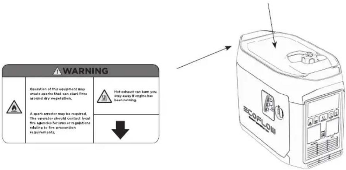
text_image
WARNING Operation of this equipment may create sparks that can start fires around dry vegetation. A spark arrestor may be required, The operator should contact local fire agencies for laws or regulations relating to fire prevention requirements. Hot exhaust can bum you. Stay away if engine has been running. ↓ ECORLOWnatural_image
Diagram of a mechanical component with an arrow indicating rotational motion (no text or symbols)natural_image
Line drawing of a car engine compartment with a water bottle pouring liquid into the engine (no text or symbols)natural_image
Technical line drawing of a mechanical component with an inset magnified detail (no text or symbols)natural_image
Illustration of a bottle being poured into a container with an arrow indicating liquid level (no text or symbols)natural_image
Line drawing of a hand inserting a device into a device labeled 'SCORON' (no text or symbols on the device itself)Ручной запуск
б) Ручной запуск
text_image
QR code image containing encoded data, no visible human-readable textnatural_image
Technical line drawing of a mechanical assembly with a magnified inset showing a cylindrical component (no text or symbols)natural_image
Technical line drawing of a mechanical assembly with two components, no visible text or symbolsnatural_image
Illustration of a cylindrical object with a textured base and a handle, alongside a separate cylindrical object (no text or symbols)natural_image
Line drawing of a container with 'ECOFLOW' branding and mounting holes (no text or symbols beyond branding)natural_image
Simple line drawing of a curved tool or device with a circular head and handle (no text or symbols)Воронка для масла

Отвертка
text_image
ECOFLOW SMART GENERATOR免責聲明
natural_image
Diagram showing a cross-shaped structure with a box and window, no text or symbols present請勿在室內使用,且須遠離門窗和通風口
natural_image
Diagram of a mechanical assembly with intersecting bands and an umbrella (no text or symbols)請勿在潮濕環境中使用
natural_image
Diagram of a device with two crossed bands and a central box, no text or symbols present添加燃料時,確保沒有燃料溢出
text_image
Diagram illustrating a mechanical or electrical setup with labeled components and distance measurement '>1m'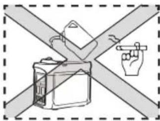
text_image
Diagram showing a hand pointing at a device against a cross-shaped barrier, with no text or symbols present.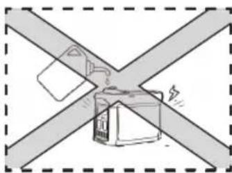
natural_image
Diagram of a battery box connected to two crossed metal bands (no text or symbols)| WARNING | ||
| Read the owner's manual and all labels before operating. | ||
| Only operate in well-ventilated areas. Using a generator indoors CAN KILL YOU IN MINUTES Generator exhaust contains carbon monoxide. This is a poison you cannot see or smell. Tampering with this CO alarm system will cause Carbon Monoxide poisoning! | ||
| Electrocution can occur if generator is used in rain, snow, or near water. Keep this unit dry at all times. Electrocution or property damage can occur. Refer to the owner's manual. | Backfeed into utility system can cause property damage and electrocution hazard. Do not connect the generator to a building's electrical system unless an isolation switch has been properly installed by a licensed electrician. | |
| Check for spilled fuel or fuel leaks. Stop engine before refueling. Do not operate near flammable materials. | ||
| When operating the generator: Never place a partition or other barrier around the generator. Do not cover the generator with a box. Do not place any objects on the generator. Turn the fuel tank cap air vent knob to "OFF" after the engine has completely cooled down. | ||

text_image
Low power generating sets MODEL: EFG100 WEIGHT: 29.3kg MAXIMUM POWER: MAX 1800W RATED FREQUENCY: 50 Hz RATED POWER(AC+DC total): COP. 1800W PERFORMANCE CLASS: CI RATED VOLTAGE: 230V QUALITY CLASS: Class A RATED CURRENT: 7.8A YEAR OF CONSTRUCTION: 2021 DC OUTPUT: 58.8V, 32A DEGREE OF PROTECTION: IP23M RATED POWER FACTOR: 1 Factory Building A202, Founder Technology Industrial Park, North Side of Songbai Highway, Longteng Community, Shiyan Sub-district, Dacan District, Shenzhen City, Guangdong, China MADE IN CHINA EcoFlow Inc. www.ecoflow.com
text_image
WARNING Operation of this equipment may create sparks that can start fires around dry vegetation. A spark arrestor may be required, The operator should contact local fire agencies for laws or regulations relating to fire prevention requirements. Hot exhaust can burn you, Stay away if engine has been running. ↓ ECORLOW2. 快速啟動
2.1 外觀描述
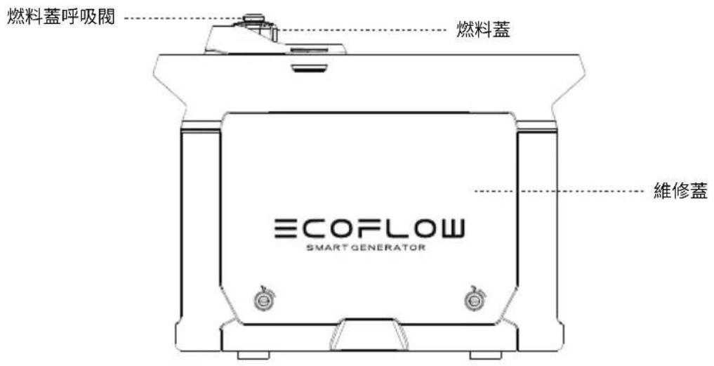
text_image
燃料蓋呼吸閥 燃料蓋 ECOFLOW SMART GENERATOR 維修蓋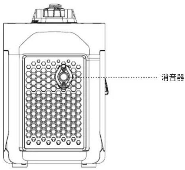
text_image
消音器natural_image
Diagram of a mechanical component with an arrow indicating rotational motion (no text or symbols)打開燃料蓋
注意
natural_image
Line drawing of a computer case with an SCOPLOM device and a circular dial indicator (no text or symbols on the device itself)移除維修蓋
推薦機油:SAE SJ 10W-40
推薦機油等級:API SJ 級或以上
機油容量:0.1 加侖/0.38 公升
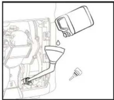
natural_image
Line drawing of a mechanical assembly with a funnel, bucket, and tool (no text or symbols)添加機油
充電電池連接
natural_image
Technical line drawing of a mechanical component with an inset magnified view of its connector detail (no text or symbols)連接正極和負極電源線
警告
每次使用發電機前,請小心檢查以下組件。
a) 檢查燃料水平
natural_image
Illustration of a bottle being poured into a container with an arrow indicating liquid level (no text or symbols)機油水平檢查
c) 檢查充電電池是否正確連接
text_image
Diagram showing hands operating a device labeled 'SCORLES' with an arrow indicating the process.手動開啟
2.4.2 關機
flowchart
graph TD
    A["ECOFLOW"] --> B["加電包連接線"]
    B --> C["DELTA Pro 智能發電機轉接器"]
https://ecoflow.com/pages/ecoflow-app.

text_image
QR code image containing encoded data, no visible human-readable text2.4.6 應用範圍
natural_image
Technical line drawing of a mechanical assembly with a magnified inset showing a pin (no text or symbols present)移除火花塞
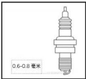
natural_image
Technical line drawing of a mechanical assembly with two components (no text or symbols)移除空氣過濾器蓋
flowchart
graph LR
    A["Person washing in a container"] --> B["Add water droplets"]
    B --> C["Add water droplets into a container"]
    C --> D["Add water droplets into a container"]
    D --> E["Add water droplets into a container"]
natural_image
Illustration of a cylindrical object with a textured base and a rectangular tool inserted into it (no text or symbols)清除任何積碳

警告
natural_image
Line drawing of a container labeled 'ECOFLOW' with no visible text or symbols beyond the label智能發電機
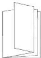
用戶手冊和保養卡
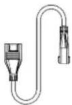
加電包連接線
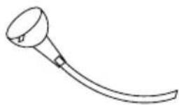
natural_image
Simple line drawing of a curved tool or device with a circular head and handle (no text or symbols)機油漏斗

螺絲批

火花塞插座

斷路器桿
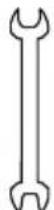
雙頭扳手
8. 電路圖
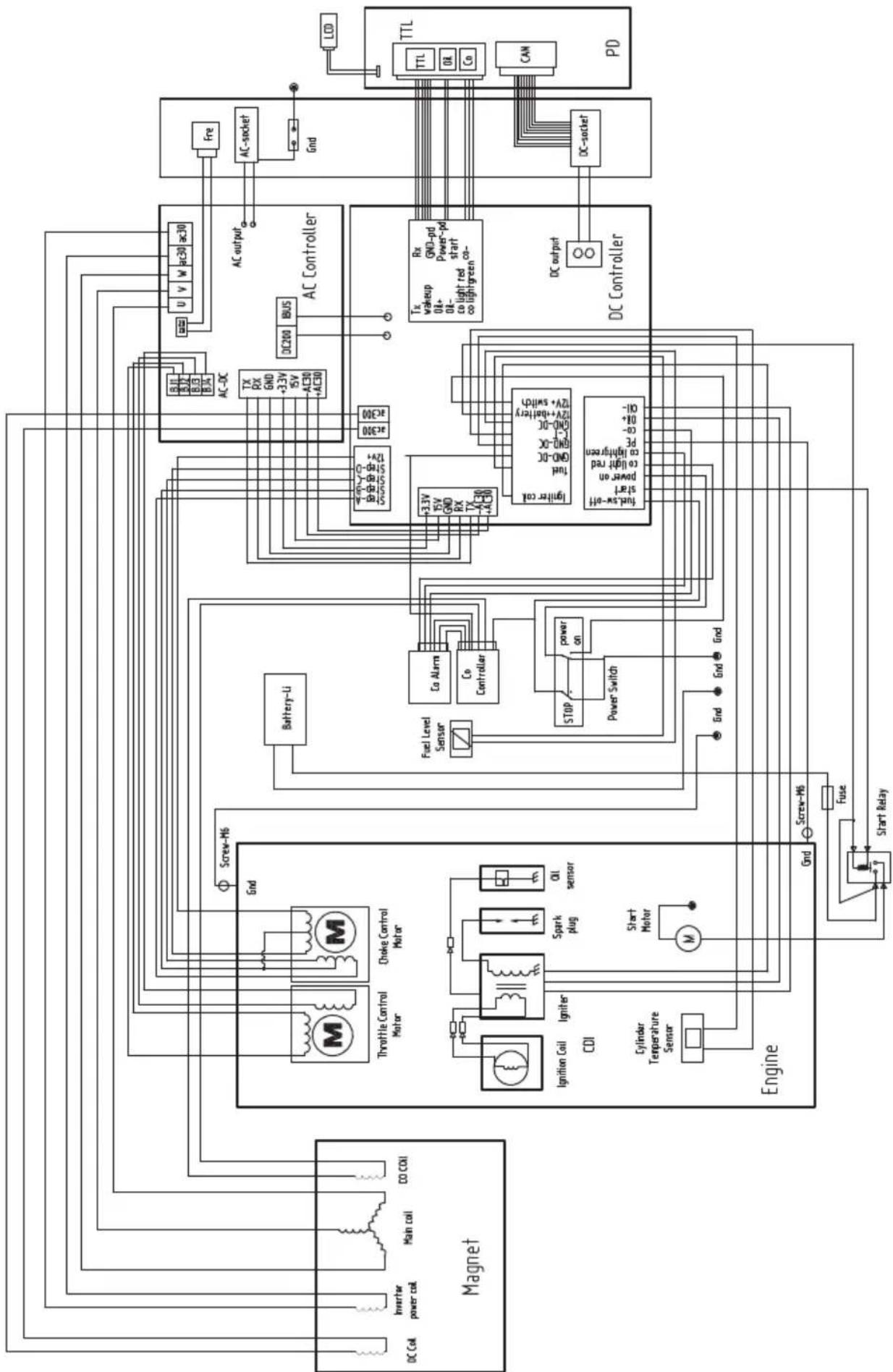
flowchart
graph TD
    subgraph Magnet
        A["DC Coil"] --> B["Inverter power coil"]
        B --> C["Main coil"]
        C --> D["CO COI"]
        E["Throttle Control Motor"] --> F["Screw-M6"]
        G["Choke Control Motor"] --> F
        H["Ignition Coil"] --> I["Igniter CDI"]
        J["Cylinder Temperature Sensor"] --> K["Start Motor"]
        L["Engine"] --> M["Screw-M6"]
        M --> N["Fuse"]
        N --> O["Start Relay"]
    end

    subgraph AC Controller
        P["AC200"] --> Q["BUS"]
        R["AC-DC"] --> S["TX RX GND +3.3V ISV AC30 +AC30"]
        T["AC-DC"] --> U["u v w ac30 ac30"]
        V["AC-DC"] --> W["Fre"]
        X["AC-DC"] --> Y["AC-DC"]
        Z["AC-DC"] --> AA["AC-DC"]
        AB["AC-DC"] --> AC["AC-DC"]
        AD["AC-DC"] --> AE["AC-DC"]
        AF["AC-DC"] --> AG["AC-DC"]
        AH["AC-DC"] --> AI["AC-DC"]
        AJ["AC-DC"] --> AK["AC-DC"]
        AL["AC-DC"] --> AM["AC-DC"]
        AN["AC-DC"] --> AO["AC-DC"]
        AP["AC-DC"] --> AQ["AC-DC"]
        AR["AC-DC"] --> AS["AC-DC"]
        AT["AC-DC"] --> AU["AC-DC"]
        AV["AC-DC"] --> AW["AC-DC"]
        AX["AC-DC"] --> AY["AC-DC"]
        AZ["AC-DC"] --> BA["AC-DC"]
        BB["AC-DC"] --> BC["AC-DC"]
    end

    subgraph PD
        DA["TTL"] --> DB["TTL"]
        DB --> DC["TTL"]
        DC --> DD["TTL"]
        DD --> AE["CAN"]
        AE --> AF
    end

    F --> F1["Ignition Coil"]
    F --> F2["Cylinder Temperature Sensor"]
    F --> F3["Screw-M6"]
    F --> F4["Splunk plug"]
    F --> F5["Oil sensor"]
    F --> F6["Start Motor"]
    F --> F7["M"]
    F --> F8["Battery-Li"]
    F --> F9["Fuel Level Sensor"]
    F --> F10["Co Alarm"]
    F --> F11["Co Controller"]
    F --> F12["STOP"]
    F --> F13["Power Switch"]
    F --> F14["+3.3V ISV GND RX TX AC30 +AC30"]
    F --> F15["Tax Low-off start power on co light red co lightgreen PE co-High-OH"]
    F --> F16[GND DC GND DC GND DC GND DC GND DC GND DC GND DC GND DC GND DC GND DC GND DC GND DC GND DC GND DC GND DC GND DC GND DC GND DC GND DC GND DC GND DC GND DC GND DC GND DC GND DC GND DC GND DC GND DC GND DC GND DC GND DC GND DC GND DC GND DC GNGPD Power-PD start co lightgreen CO lightgreen CO lightgreen CO lightgreen CO lightgreen CO lightgreen CO lightgreen CO lightgreen CO lightgreen CO lightgreen CO lightgreen CO lightgreen CO lightgreen CO lightgreen CO lightgreen CO lightgreen CO lightgreen CO lightgreen CO lightgreen CO lightgreen CO lightgreen CO lightgreen CO lightgreen CO lightgreen CO lightgreen CO lightgreen CO lightgreen CO lightgreen CO lightgreen CO lightgreen CO lightgreen CO lightgreen CO lightgreen CO lightgreen CO Light Green Power Pd Start Co Light Green Power Pd Start Co Light Green Power Pd Start Co Light Green Power Pd Start Co Light Green Power Pd Start Co Light Green Power Pd Start Co Light Green Power Pd Start Co Light Green Power Pd Start Co Light Green Power Pd Start Co Light Green Power Pd Start Co Light Green Power Pd Start Co Light Green Power Pd Start Co Light Green Power Pd Start Co Light Green Power Pd Start Co Light Green Power Pd Start Co LightGreen Power Pd Start Co Light Green Power Pd Start Co Light Green Power Pd Start Co Light Green Power Pd Start Co Light Green Power Pd Start Co Light Green Power Pd Start Co Light Green Power Pd Start Co Light Green Power Pd Start Co Light Green Power Pd Start Co Light Green Power Pd Start Co Light Green Power Pd Start Co Light Green Power Pd Start Co Light Green Power Pd Start Co Light Green Power Pd Start Co Light Green PowerPd Start Co Light Green Power Pd Start Co Light Green Power Pd Start Co Light Green Power Pd Start Co Light Green Power Pd Start Co Light Green Power Pd Start Co Light Green Power Pd Start Co Light Green Power Pd Start Co Light Green Power Pd Start Co Light Green Power Pd Start Co Light Green Power Pd Start Co Light Green Power Pd Start Co Light Green Power Pd Start Co Light Green Power Pd Start Co Light Green Power Pd End

    subgraph Control
        C
        D
        E
        F
        G
        H
        I
        J
        K
        L
        M
        N
        O
        P
        Q
        R
        S
        T
        U
        V
        W
        X
        Y
        Z
        AA
        AB
        AC
        AD
    end

    subgraph Control
        AC
        AC
        AC
        AC
    end

    subgraph Control
        AC
        AC
        AC
    end

    subgraph Control
        AC
        AC
        AC
    end

    subgraph Control
        AC
        AC
        AC
    end

    subgraph Control
        AC
        AC
        AC
    end

    subgraph Control
        AC
        AC
        AC
    end

    subgraph Control
        AC
        AC
        AC
    end

    style Control fill:#f9f,stroke:#333,stroke-width:2px