IVM 60242 M ACD WS - Vacuum Cleaner Kärcher - Free user manual and instructions
Find the device manual for free IVM 60242 M ACD WS Kärcher in PDF.
| Product type | Water and dust vacuum cleaner, dust class M |
| Brand | Kärcher |
| Model | IVM 60242 M ACD WS |
| Dimensions (W x D x H) | 1020 x 680 x 1490 mm |
| Weight | 108 kg |
| Power supply | 220-240 V, 50-60 Hz, 1 phase, 2100 W (max 2400 W) |
| Tank volume | 60 L |
| Inert liquid tank volume | 20 L |
| Suction volume | 8 L |
| Max. vacuum | 25.4 kPa |
| Air flow | 2 x 74 L/s |
| Filtration area | 2.24 m² |
| Suction hose connection | DN40/50 (adaptable DN70) |
| Main functions | Dry and wet suction, combustible dust class M, industrial use |
| Maintenance and cleaning | Empty the collector after use, clean with damp cloth, regular replacement of main filter and microfiber |
| Safety | Equipotential bonding, parking brake, IPX4 protection, protection class I |
| Spare parts and repairability | Main filter (ref. 9.439-542.0), microfiber (ref. 9.990-103.0), mains cable (ref. 6.650-035.0) |
| General information | Professional and industrial use, compliant with EN 60335-2-69, warranty according to Kärcher conditions |
Frequently Asked Questions - IVM 60242 M ACD WS Kärcher
User questions about IVM 60242 M ACD WS Kärcher
0 question about this device. Answer the ones you know or ask your own.
Ask a new question about this device
Download the instructions for your Vacuum Cleaner in PDF format for free! Find your manual IVM 60242 M ACD WS - Kärcher and take your electronic device back in hand. On this page are published all the documents necessary for the use of your device. IVM 60242 M ACD WS by Kärcher.
USER MANUAL IVM 60242 M ACD WS Kärcher
natural_image
Technical line drawing of a vacuum cleaner on a wheeled cart (no text or symbols)Deutsch 5
English 18
Français 30
Italiano 44
Español 57
Português 70
Nederlands 83
Türkçe 96
Svenska 108
Suomi 119
Norsk 131
Dansk 142
Eesti 154
Latviešu 166
Lietuviškai 178
Polski 190
Magyar 203
Čeština 216
Slovenčina 228
Slovenščina 241
Româneşte 252
Hrvatski 266
Srpski 278
Ελληνικά 290
Русский 304
Українська 320
Қазақша 334
Български 348
中文 363
العربيya 373

001
EAC
Read Online

99902620
(04/24)

Register your product
www.kaercher.com/welcome
natural_image
Illustration of an open book with a black arrow indicating rotation (no text or symbols)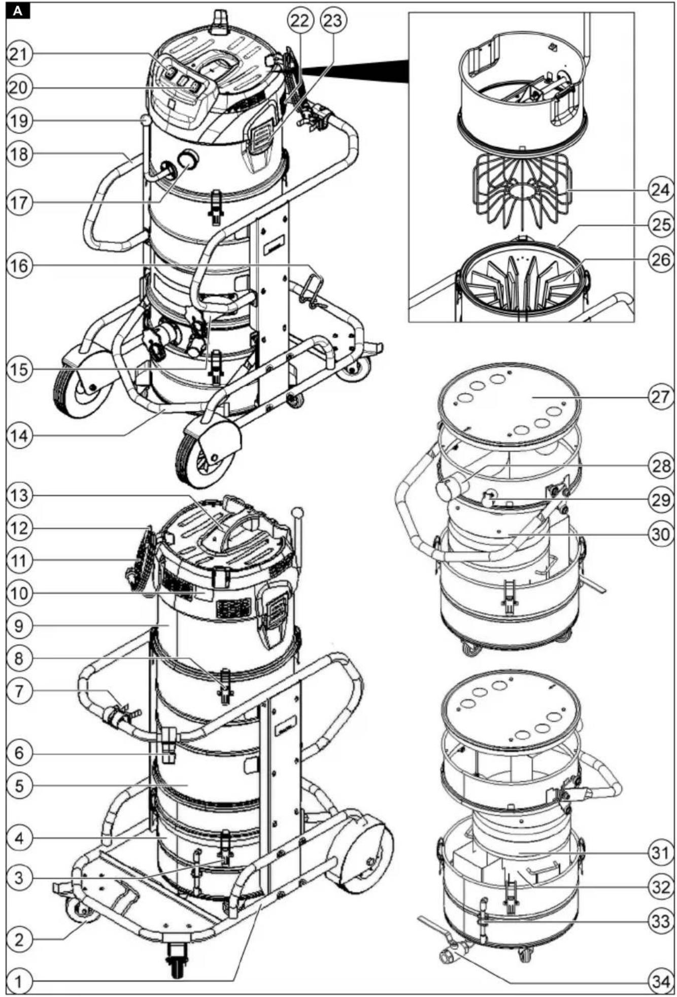
natural_image
Technical illustration of two mechanical assembly steps showing pipe connection and component positioning (no text or symbols)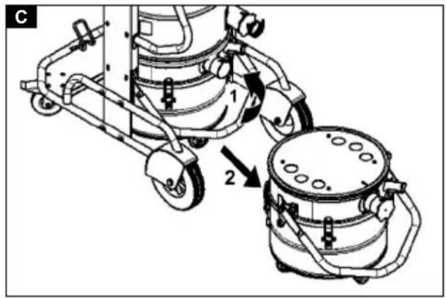
natural_image
Technical line drawing of a wheeled vehicle chassis with wheels and suspension components (no text or symbols)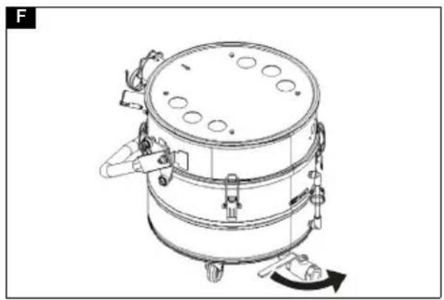
natural_image
Technical line drawing of a cylindrical industrial vessel with mounting flanges and internal components (no text or symbols)Inhalt
natural_image
Mechanical device with wheels and a cross symbol indicating a mechanical component (no text or labels)natural_image
Technical line drawing of a mechanical assembly with no visible text or symbols73550 Waldstetten (Germany)
Tel.: +49 7171 94888-0
Fax: +49 7171 94888-528
Waldstetten, 24/04/01
Contents
General instructions 18
Safety information 18
Intended use 19
Environmental protection 20
Accessories and spare parts...... 20
Scope of delivery 20
Description of the device.... 20
Symbols on the device.... 21
Initial startup.... 21
Operation 23
Transport.... 26
Storage 26
Care and maintenance.... 26
Troubleshooting guide.... 28
Disposal 28
Warranty.... 28
Technical data 29
Declaration of Conformity 29
General instructions
Read these original instructions before using your device for the first time, adhere to the instructions contained therein and store them for later reference or subsequent owners.
- Be sure to read the safety instructions no. 5.956-249.0 prior to the initial start-up.
- If the operating instructions and safety instructions are not observed, the device can be damaged and dangers could arise for users and other persons.
- Notify the dealer immediately in the case of shipping damage.
Safety information
Hazard levels
⚠️DANGER
- Indication of an imminent threat of danger that will lead to severe injuries or even death.
⚠ WARNING
- Indication of a potentially dangerous situation that may lead to severe injuries or even death.
△CAUTION
- Indication of a potentially dangerous situation that may lead to minor injuries.
ATTENTION
- Indication of a potentially dangerous situation that may lead to damage to property.
General safety instructions
⚠️ DANGER ● Only trained personnel are permitted to use the device and the substances for which it is to be used, including the safe procedure for disposing of the vacuumed material. ● An air exchange rate L must be present in the room when the exhaust gas is returned into the room. To remain within the required limit values, the volume flow of returned air must be no greater than 50% of the fresh air volume (room volume V_R x air exchange rate L_W ). Without special ventilation measures, the following applies: L_W=1h^-1 . ● This device contains dust that is harmful to your health. Emptying and maintenance, including removal of the dust bag, may only be performed by technical specialists wearing suitable personal protective equipment.
- Do not operate the device without the complete filtration system. - Observe the applicable safety instructions for the materials being vacuumed. - The simultaneous collection of different combustible dusts in the collection container can lead to fires or explosion. - Make sure that the correct liquid for collecting metal dust is used in the liquid container in order to avoid dangerous reactions. To avoid the formation of hydrogen gas with metal dusts, the use of oil instead of water is recommended.
⚠ WARNING • You must not set up or operate the device in areas where there is a risk of dust or gas explosion. A dust explosive atmosphere inside the device is only allowed in front of the filter. Gas explosive atmospheres are prohibited inside the device. • The device is not suitable for the suctioning or vacuuming of flammable liquids (flammable, easily flammable, highly flammable according to Dangerous Substances Directive 67/548/EEC) (flash point below 55 °C) and mixtures of flammable dusts and liquids. • The device is not suitable
ble for sucking up ignition sources and dusts with a glow temperature ≤ 190 ^ C.
- Every time before use, check whether the equipotential bonding conductors (earthing conductors) are connected. • The device must not be used or stored outdoors in wet conditions. • Apply the parking brake at the steering roller to ensure a secure footing for the device. The device may move uncontrollably if the parking brake is open. • Fill the liquid container only with the liquids recommended by the manufacturer.
⚠️ CAUTION ● In case of longer breaks in operation and after use, switch off the device at the power switches and unplug the mains plug.
ATTENTION • Only use the device indoors. • Risk of crushing! Wear gloves when removing or installing the suction head, filter inlay or collection container.
- Risk of damage! Never vacuum without a filter or with a damaged filter. ● Wear safety shoes when operating the device. ● Only move the device at walking speed, and to move down a decline, have two workers steady the device as necessary. ● Be careful to ensure that there is no dust spillage when replacing accessories. ● Surface temperatures can rise to 135°C during normal operation. ● Avoid kinking the suction hose unit. ● Carry out a regular visual inspection of the hoses. ● Take appropriate precautions for removal, handling, storage and disposal of the sludge, such as mixing with inert liquids according to local regulations. ● Hydrogen gas is flammable and can be produced by extracting up certain materials such as aluminium, magnesium, etc. The valve prevents the accumulation of hydrogen gas inside the liquid container. Clean and inspect the valve regularly and check for signs of damage. ● Ensure adequate ventilation of the installation site to reduce the hydrogen concentration. ● Empty the dirt receptacle after each use and when it is full of sludge to reduce the formation of hydrogen gas.
Electrical connection
The device may only be connected to an electrical connection which has been set up by a qualified electrician as per IEC 60364. For connected loads see Technical data and type plate.
⚠️DANGER
Danger of electric shock
Danger of death
Avoid damaging the power cables by driving over them or otherwise crushing them, or by jerking them.
Protect the cables from heat, oil and sharp edges.
Check the mains connection of the device for damage every time before operation.
Do not operate the device using a damaged cable. Have any damaged cables replaced by a qualified electrician.
Behaviour in the event of an emergency
⚠️DANGER
Risk of injury and damage in the event of a short-circuit or other electrical faults
Danger of electric shock, danger of burns Switch off the device and unplug the mains plug.
Behaviour in case of filter breakage / leakage:
-
Switch off the unit immediately. The unit may not be operated without the fresh water filter.
-
Replace the filter.
Intended use
The device is intended for:
- Wet and dry cleaning of floor and wall surfaces
- Vacuuming of dry, flammable, deposited dusts hazardous to health; dust class M according to EN 60335-2-69
• Vacuuming of non-explosive substances - Vacuuming of flammable dusts of all dust explosion classes
• Vacuuming of dusts and coarse dirt - Vacuuming of flammable dusts from a zone 22 if the device is installed outside of potentially explosive areas
- Vacuuming moist and liquid substances - Vacuuming of the following substances only when using inert liquid:
- Titanium dust
- Explosive and conductive dust
– Magnesium dust or powder -
Condensate dusts and explosive metal powders from additive manufacturing (3D printing)
-
Industrial usee.g. in storage and production areas
- Commercial use, e.g. in hotels, schools, hospitals, factories, shops, offices, and rental companies.
A corresponding Ex device must be used if there is a classified Ex zone at the device installation location.
The device's correct function is only guaranteed when using suction hose nominal widths of DN40 and DN50.
Any other use constitutes improper use. The device is not suitable for:
- Vacuuming of ignition sources and dusts with a glow temperature ≤ 190 °C
- Vacuuming of explosive substances or substances classified as such in the sense of §1 German Explosives Law "Explosive vapour-air mixtures" (§1 SprengG, explosiver Dampf-Luft-gemische)
- vacuuming of mixtures of flammable liquids and flammable dust
- Vacuuming of smouldering or hot particles where this could otherwise result in a fire or an explosion
• Vacuuming of toxic substances
- Connection to a dust-generating machine
Environmental protection

The packing materials can be recy- cled. Please dispose of packaging in accordance with the environmental regulations.

Electrical and electronic devices contain valuable, recyclable materials and often components such as batteries, rechargeable batteries or oil, which - if handled or disposed of incorrectly - can pose a potential danger to human health and the
environment. However, these components are required for the correct operation of the device. Devices marked by this symbol are not allowed to be disposed of together with the household rubbish.
Notes on the content materials (REACH)
Current information on content materials can be found at: www.kaercher.de/REACH
Accessories and spare parts
⚠️DANGER
Risk of explosion when used with non-permitted accessories
Only use accessories permitted by the manufacturer and with the Ex label for type 22 usage.
Only use original accessories and original spare parts. They ensure that the appliance will run safely and fault-free.
Information on accessories and spare parts can be found at www.kaercher.com.
Note
No accessories are included in the scope of delivery. The accessories must be ordered separately depending on the application.
Scope of delivery
Check the contents for completeness when unpacking. In the event of shipping damage, please notify your dealer.
Description of the device
For the illustrations, refer to the graphics page
Illustration A
①Chassis
② Steering roller with parking brake
③Clamping straps on the dirt receptacle
④Dirt receptacle
⑤Filter ring
⑥Cable clips
⑦Suction pipe holder
⑧ Spacer lock
⑨Spacer
⑩Type plate
⑪Mains cable
⑫Cable hooks
⑬Carrying handle
⑭Bow handle of the dirt receptacle
⑮Suction hose port without wet separator
⑯ Floor nozzle holder
⑰Pressure gauge
⑱Push handle
⑲Filter dedusting lever
⑳Suction turbine trigger 2
②1 Suction turbine trigger 1
⑳Suction head
23 Suction head lock
24 Filter vibrator
⑳Sealing ring
26filter
⑳Mechanical switch-off
⑳Suction hose port with wet separator
⑲Venting valve
30 Filter foam
③1 Micro-fleece
③2 Strainer basket
③3 Filling level hose
③4 Ball tap
Symbols on the device
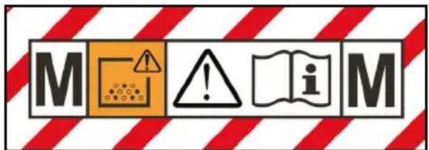
The device is suitable for vacuuming dusts up to dust class M.
⚠ WARNING
Damage to the skin, lungs and eyes
Expulsion of fine dust during emptying and maintenance work and disposal
Wear the prescribed personal protective gear when performing during emptying and maintenance work, including disposal of the dust bag.
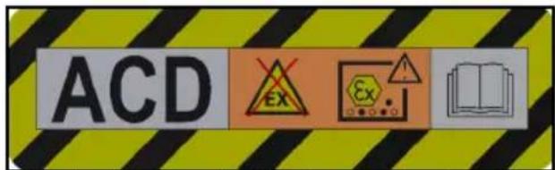
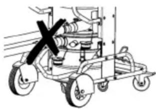
The device is suitable for vacuuming flammable dusts, installation outside zone 22.
WARNING: This device must not be placed in any zone 22. If a zone 22 is present, an EX-device must be used.
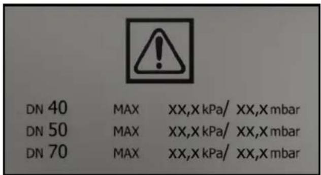
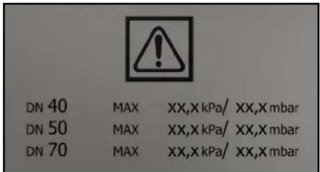
The maximum vacuum value in relation to the hose cross-section is specified on the label. The actual value can be read on the pressure gauge. For the values applicable to this device, see chapter Reading the minimum volumetric flow. If this value is not reached, the filter must be replaced, (see chapter Replacing the main filter). The various different hose cross-sections allow adaptation to the various different connection cross-sections of the accessories.

Micro-fleece
(Order no. 9.990-103.0)
Main filter
(Order no. 9.439-542.0)
Initial startup
⚠ WARNING
Potential equalisation line not connected correctly
Electric shock
Every time before use, check whether the equipotential bonding conductor (earthing conductors) are connected.
⚠ WARNING
Danger from dust that is harmful to your health
Respiratory sicknesses through inhalation of dust.
Do not vacuum without correctly installed filter elements, otherwise a danger to health from increased fine dust emission is present.
⚠ WARNING
Improper handling when locking the dirt receptacle
Risk of crushing
Under no circumstances should you hold your hands between the dirt receptacle and filter ring or allow them to come close to the lifting mechanism while locking it. Lock the dirt receptacle by operating the bow handle with both hands.
ATTENTION
Missing filter element
Damage to the suction motor
Do not vacuum without a filter element.
ATTENTION
Static charge of the dirt receptacle
Ignition of dusts
Make sure that the grounding on the chassis is in contact with the dirt receptacle.
- Bring the device into the working position.
- Secure the device with the parking brakes.
- Ensure that the suction head is fitted correctly.
- Fill the dirt receptacle with water or oil (order no. 9.990-272.0) up to the mark (see chapter Fill the dirt receptacle with inert liquid).
- Clamp the earth terminal to the external equipotential bonding.
- Remove the sealing plug on the collection container (see chapter Selecting the suction connection).
- Insert the suction hose into the suction connection.
- Ensure that the suction connection on the filter ring is tightly sealed with a sealing plug (see chapter Closing the suction connection).
- Check the filling level in the dirt receptacle (see chapter Check the dirt receptacle filling level).
- Empty the dirt receptacle if necessary (see chapter Emptying the dirt receptacle).
- Plug the desired accessories (not included in the scope of delivery) onto the suction hose.
- Ensure that the dirt receptacle is correctly fitted.
Selecting the suction connection
The device is equipped with 2 suction hose ports.
- Suction hose port on the dirt receptacle – Dry vacuuming with wet separator: Fine dust, powder The dirt receptacle with wet separation function must be filled with the inert liquid water or oil. Oil with order no. 9.990-272.0 is recommended.
- Suction hose port on the filter ring is tightly sealed with a sealing plug when used as intended.
natural_image
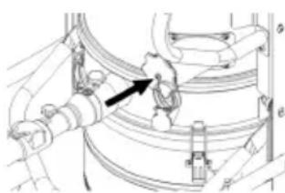
Mechanical assembly diagram showing a cart with wheels and a central valve (no text or labels)Two suction hoses must not be connected to the vacuum cleaner at the same time. Only the lower suction hose port may be used when used as intended.
natural_image
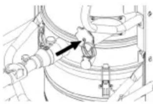
Technical line drawing of a mechanical assembly with no visible text or symbolsThe upper suction hose port must be tightly closed when using the wet separator.
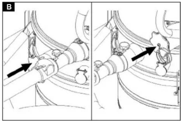
Closing the suction connection
⚠ WARNING
Risk of injury
Damage to the skin, lungs and eyes through fine dust
The suction connection must be closed using the sealing plug after removing the suction hose.
Illustration B
- Insert the sealing plug precisely into the suction connection.
- Push the sealing plug in all the way to the end stop.
- Turn the sealing plug to the right until the suction connection is tightly closed.
Fill the dirt receptacle with inert liquid
If a dirt receptacle with wet separator is used, the dirt receptacle must be filled with inert liquid before use.
⚠ WARNING
Moving parts
Risk of crushing
Be careful of moving parts when removing or inserting the upper part of the dirt receptacle.
- Secure the device with the parking brakes.
Illustration C
- Pull the bow handle up.
The dirt receptacle is unlocked and lowered.
- Pull the dirt receptacle out of the device by the bow handle.
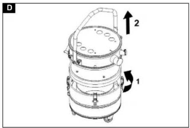
Illustration D
- Loosen the clamping straps on the dirt receptacle.
- Remove the upper part of the dirt receptacle by the bow handle.
- Fill the inert liquid water or oil into the dirt receptacle until the filling level reaches the mark on the filling level indicator.
- When fitting the upper part of the dirt receptacle, make sure that the float ball is inserted into the corresponding guide.
⚠ WARNING
Improper handling when locking the dirt receptacle
Risk of crushing
Under no circumstances should you hold your hands between the dirt receptacle and filter ring or allow them to come close to the lifting mechanism while locking it.
Lock the dirt receptacle by operating the bow handle with both hands.
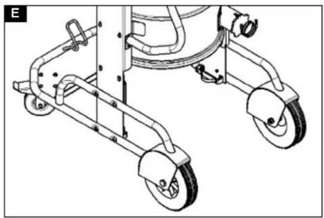
Illustration E
ATTENTION
Static charge of the dirt receptacle
Ignition of dusts
Make sure that the grounding on the chassis is in contact with the dirt receptacle.
- Fit the dirt receptacle in the reverse sequence and lock it with the bow handle.
Check the dirt receptacle filling level
The dirt receptacle must be emptied when filled up to the mark. The device does not switch off automatically when the maximum filling level is exceeded.
- Check the dirt receptacle filling level regularly.
- Make sure that no more than 8 litres of material are sucked in during vacuuming.
Operation
⚠️DANGER
Suction of explosive and conductive metal dust without inert liquid
Explosion hazard, heat generation
Never vacuum explosive and conductive suction material without inert liquid.
⚠ WARNING
Danger from dust that is harmful to your health
Respiratory sicknesses through inhalation of dust.
Do not vacuum without correctly installed filter elements, otherwise a danger to health occurs from increased fine dust emission.
Before each use, check that both filter elements are correctly installed.
ATTENTION
Risk of damage to the suction motor.
Never remove the main filter element when vacuuming.
ATTENTION
Lack of inert liquid
Damage to the wet separator
Never vacuum without inert liquid when using the suction hose port on the wet separator.
Switching on the device
- Plug the mains plug into the socket.
- Switch on the device via the suction turbine power switches.
Note
Always switch the suction turbines on and off one after the other. For the correct function of the pressure gauge for monitoring the minimum volume flow, all suction turbines must be switched on.
Note
In most application cases it is sufficient that you vacuum with one suction turbine. If
necessary, switch on the 2nd suction turbine. However, do not operate the device with both suction turbines for longer than 15 min. This can cause too much humid air to prematurely wet the main filter. If necessary, let the main filter dry afterwards or replace it (see chapter Replacing the main filter).
- Start the vacuuming process.
Performing the vacuuming process
- Regularly check the filling level in the dirt receptacle, since the device does not switch off automatically.
Note
The device is equipped with a mechanical monitoring unit. This monitoring unit interrupts the airflow when the inert liquid falls below the minimum filling level. Refill with inert liquid to continue the vacuuming process (see chapter Fill the dirt receptacle with inert liquid).
- Make sure that no more than 8 litres of material are sucked in during vacuuming.
- If necessary, empty the dirt receptacle (see chapter Emptying the dirt receptacle).
- If necessary, replace the main filter (see chapter Replacing the main filter).
Note
If the dirt receptacle is filled with an inert liquid, moist air may flow through the main filter during suction and soak it. Check the main filter for moisture after the vacuuming process. If necessary, let the main filter dry or replace it (see chapter Replacing the main filter).
Reading the minimum volumetric flow
A pressure gauge showing the vacuum inside the device is mounted on the front of the device. The main filter must be cleaned when the maximum vacuum (see table) is reached, see chapter Replacing the main filter). This value depends on the device performance and the suction hose used. If the vacuum is not significantly reduced by replacing the filter, there must be another problem (see chapter Troubleshooting guide).
ATTENTION
Exceeding the maximum vacuum
Suction loss
If the specified value is exceeded, the air speed in the suction hose drops below 20 m/s. Replace the filter.
| Nominal width of the suction hose | Maximum vacuum |
| DN40 16.4 kPa (164 mbar) | |
| DN50 12.9 kPa (129 mbar) | |
| DN70 --- |
Switching off the device
- Switch off the device via the suction turbine power switches.
- Pull out the mains plug.
- Disconnect the earth terminal from the external equipotential bonding.
Each time after use
- Remove the accessories.
- Close the suction connection (see chapter Closing the suction connection).
- Remove the accessories and, if necessary, flush with water and allow to dry.
- Empty the dirt receptacle (see chapter Emptying the dirt receptacle).
- Vacuum the inside and outside of the device and clean with a moist cloth.
Emptying the dirt receptacle
The dirt receptacle must be emptied if necessary and after each use.
The inlet opening or the suction hose are closed.
Regularly check the filling level in the dirt receptacle, since the device does not switch off automatically.
- Switch off the device.
- Secure the device with the parking brakes.
Illustration C
- Pull the bow handle up.
The dirt receptacle is unlocked and lowered. - Pull the dirt receptacle out of the device by the bow handle.
Illustration D
-
Loosen the clamping straps on the dirt receptacle.
-
Remove the upper part of the dirt receptacle by the bow handle.
-
Remove the foam element from the lower part of the dirt receptacle.
-
Remove the strainer basket with the micro-fleece.
-
Remove the micro-fleece from the strainer basket.
-
Dispose of the micro-fleece in accordance with statutory regulations.
-
If necessary, drain the inert liquid from the dirt receptacle (see chapter Drain the inert liquid from the dirt receptacle).
Note
You can use the inert liquid several times if necessary.
- When fitting the upper part of the dirt receptacle, make sure that the float ball is inserted into the corresponding guide.
⚠ WARNING
Improper handling when locking the dirt receptacle
Risk of crushing
Under no circumstances should you hold your hands between the dirt receptacle and filter ring or allow them to come close to the lifting mechanism while locking it.
Lock the dirt receptacle by operating the bow handle with both hands.
Illustration E
ATTENTION
Static charge of the dirt receptacle
Ignition of dusts
Make sure that the grounding on the chassis is in contact with the dirt receptacle.
- Fit the dirt receptacle in the reverse sequence and lock it with the bow handle.
Drain the inert liquid from the dirt receptacle
- Switch off the device.
- Secure the device with the parking brakes.
- Close the suction connection (see chapter Closing the suction connection).
Illustration C
-
Pull the bow handle up. The dirt receptacle is unlocked and lowered.
-
Pull the dirt receptacle out of the device by the bow handle.
Illustration F
-
Turn the lever on the ball tap by 90^ .
-
Turn the lever to the original position when the collection container is completely empty.
⚠ WARNING
Improper handling when locking the dirt receptacle
Risk of crushing
Under no circumstances should you hold your hands between the dirt receptacle and filter ring or allow them to come close to the lifting mechanism while locking it.
Lock the dirt receptacle by operating the bow handle with both hands.
Illustration E
ATTENTION
Static charge of the dirt receptacle
Ignition of dusts
Make sure that the grounding on the chassis is in contact with the dirt receptacle.
- Fit the dirt receptacle and lock it with the bow handle.
Cleaning the device
⚠ WARNING
Improper disposal of waste water
Environmental pollution
Observe the local waste water treatment regulations.
-
Vacuum the inside and outside of the device and clean with a moist cloth. A vacuum cleaner with the same or better classification must be used for vacuuming the device.
-
If necessary, rinse the accessories (not included in the scope of delivery) with water and dry them.
Storing the device
-
Wind the mains cable onto the cable holders.
-
Store the device in a dry room and secure it against unauthorised use.
Transport
△CAUTION
Failure to observe the weight
Risk of injury and damage
Be aware of the weight of the device during transportation.
The dirt receptacle is emptied.
-
Close both suction connections for dust-free transport (see chapter Closing the suction connection).
-
Release the parking brakes and push the device by the push handle.
-
Grasp the device by the chassis and the push handle for loading.
-
Secure the device against slipping and tipping over when transporting in vehicles.
Storage
△CAUTION
Failure to observe the weight
Risk of injury and damage
Be aware of the weight of the device during storage.
The dirt receptacle is emptied.
- Store the device indoors only.
Care and maintenance
⚠️DANGER
Inadvertently starting up device, touching live components
Risk of injury, electric shock
Switch off the device before performing any work on the device.
Remove the mains plug.
⚠️DANGER
Danger from dust that is harmful to your health
Respiratory sicknesses through inhalation of dust.
Wear a breathing protection mask of class P2 or higher and disposable clothing when performing maintenance work (e.g. filter change).
⚠ WARNING
Danger from dust that is harmful to your health
Respiratory sicknesses through inhalation of dust.
Safety devices providing hazard protection must be checked for correct safety-related functionality at least annually by the manufacturer or an appropriately instruction person, e.g. absence of leaks, filter damage, functionality of the monitoring devices.
ATTENTION
Care agents containing silicone
These can attach plastic components.
Do not use care agents containing silicone for cleaning.
Dust extraction machines are safety devices for the prevention or elimination of hazards according to the German BGV A1.
- For servicing performed by the user, the device must be disassembled, cleaned and maintained only to the degree that this is possible without presenting a danger to the maintenance personnel and other persons. Suitable precautionary measures include detoxification before disassembly. Make provisions for local forced ventilation at the location where the device is to be disassembled, for cleaning the maintenance surface and to ensure adequate protection for the personnel.
- The exterior of the device should be detoxified by vacuuming and wiped clean, or treated with sealant before being removed from the hazardous area. All device parts must be regarded as contaminated when they are taken from the hazardous area. Suitable measures must be taken to prevent distribution of the dust.
- All contaminated objects resulting from maintenance and repair work that cannot be satisfactorily cleaned must be correctly disposed of. Such objects must
be disposed of in sealed bags in accordance with the applicable regulations for the disposal of this type of waste.
- The suction hose ports are to be closed using the sealing plugs during transport and maintenance of the device.
- Note that you can carry out simple maintenance and care work yourself.
- Clean the surface of the device and the interior of the container regularly with a moist cloth.
- Carry out a regular visual inspection for clogging of the hoses.
Inspection and maintenance work
Have the device regularly inspected according to the respective national accident prevention regulations. Maintenance work as specified by the manufacturer must be performed by a technically qualified person at the specified regular intervals and in accordance with the applicable regulations and safety requirements. Work on electrical components may only be performed by a qualified electrician. Please contact a KÄRCHER branch office if you have any questions.
Replacing the main filter
- Switch off the device.
- Pull out the mains plug.
- Unlock and remove the suction head.
- Unlock and remove the spacer.
- Remove the contaminated star pleated filter.
- Immediately after removing the contaminated star pleated filter from the unit, place it in a bag and seal the bag tightly.
- Dispose of the contaminated star pleated filter according to legal requirements.
- Remove any dirt deposits from the clean air side.
-
Check the sealing ring for damage.
-
Insert the new star pleated filter: a Pull the new star pleated filter over the filter vibrator on the spacer such that the vibrating elements are aligned centrally in the filter bags.
b Place the spacer with star pleated filter and filter vibrator on the filter ring. c Lock the spacer.
- Fit and lock the suction head.
Replacing the micro-fleece
- Switch off the device.
- Secure the device with the parking brakes.
- Pull the bow handle up.
The dirt receptacle is unlocked and lowered. - Pull the dirt receptacle out of the device by the bow handle.
Illustration C
Illustration D
- Loosen the clamping straps on the dirt receptacle.
- Remove the upper part of the dirt receptacle by the bow handle.
- Remove the foam element from the lower part of the dirt receptacle.
- Remove the strainer basket with the micro-fleece.
-
Remove the micro-fleece from the strainer basket.
-
Dispose of the micro-fleece in accordance with statutory regulations.
-
Insert the new micro-fleece.
-
When fitting the upper part of the dirt receptacle, make sure that the float ball is inserted into the corresponding guide.
⚠ WARNING
Improper handling when locking the dirt receptacle
Risk of crushing
Under no circumstances should you hold your hands between the dirt receptacle and filter ring or allow them to come close to the lifting mechanism while locking it.
Lock the dirt receptacle by operating the bow handle with both hands.
Illustration E
ATTENTION
Static charge of the dirt receptacle Ignition of dusts
Make sure that the grounding on the chassis is in contact with the dirt receptacle.
- Fit the dirt receptacle in the reverse sequence and lock it with the bow handle.
Troubleshooting guide
⚠️DANGER
Unintentional start-up of the device / electric shock
Unintentional start-up of the suction motor can cause injuries. Voltage present on electrical parts can cause an electric shock.
Switch off the device and unplug the mains plug before performing any work on the device.
Have all checks and work on electrical parts performed by an qualified technician.
Note
The device must be switched off immediately in the event of a malfunction. The malfunction must be eliminated before switching the device on again.
If the malfunction cannot be corrected, the device must be checked by the Customer Service department.
Suction turbine does not start up
- Check the socket and the power supply fuse.
- Check the mains cable and the mains plug of the device.
- Switch the device on.
Suction power decreases
-
Close the unsealed suction connection (see chapter Closing the suction connection).
-
Remove the blockages from the suction nozzle, the suction pipe or the suction hose.
-
Check that the suction head and the dirt receptacle are correctly seated.
-
Empty the dirt receptacle (see chapter Emptying the dirt receptacle).
-
Check the seating of the filter and correct if necessary.
-
Replace the main filter (see chapter Replacing the main filter).
-
Replace the micro-fleece (see chapter Replacing the micro-fleece).
-
Check the condition of the inert liquid.
a Check the filling level of the inert liquid, top up the inert liquid if necessary (see chapter Fill the dirt receptacle with inert liquid).
b Check the quality of the inert liquid, replace the inert liquid if necessary (see chapter Drain the inert liquid from the dirt receptacle and chapter Fill the dirt receptacle with inert liquid).
Suction power not present
The mechanical switch-off interrupts the volume flow because there is too little inert liquid in the dirt receptacle.
- Top up the inert liquid (see chapter Fill the dirt receptacle with inert liquid).
Escaping dust when vacuuming
- Check the seating of the dirt receptacle.
- Check the seating of the filter and correct if necessary.
- Replace the main filter (see chapter Replacing the main filter).
- Top up with inert liquid when using the device with a wet separator (see chapter Fill the dirt receptacle with inert liquid).
Disposal
At the end of its service life, the device is to be disposed of in accordance with statutory regulations.
Warranty
The warranty conditions issued by our relevant sales company apply in all countries. We shall remedy possible malfunctions on your appliance within the warranty period free of cost, provided that a material or manufacturing flaw is the cause. In a warranty case, please contact your dealer (with the purchase receipt) or the next authorised customer service site.
(See overleaf for the address)
Further warranty information (if available) can be found in the service area of your local Kärcher website under "Downloads".
Technical data
| Electrical connection | ||
| Mains voltage V 220- | 240 | |
| Phase ~ 1 | ||
| Power frequency Hz 50-60 | ||
| Nominal power W 2100 | ||
| Maximum power W 2400 | ||
| Protection type IPX4 | ||
| Protection class I* | ||
| Maximum permissible mains grid impedance | Ω 0.195+ j0.122 | |
| Dimensions and weights | ||
| Typical operating weight | kg | 108 |
| Length x width x height | mm | 1020 x 680 x 1490 |
| Filter area | m2 | 2.24 |
| Ambient conditions | ||
| Storage temperature °C | -10-40 | |
| Device performance data | ||
| Container capacity | l | 60 |
| Inert liquid container ca-pacity | l | 20 |
| Suction material container capacity | l | 8 |
| Vacuum (with pressure re-lief valve) | kPa | 25.4 |
| Air quantity | l/s | 2x 74 |
| Suction hose connection | DN70 | |
| Nominal width of the suc-tion hose | DN40/50 | |
| Filter order number | 9.439-542.0 | |
| Determined values in acc. with EN 60335-2-69 | ||
| Hand-arm vibration value | m/s2 | <2.5 |
| K uncertainty | m/s2 | 0.2 |
| Sound pressure level LpA | dB(A) | 79 |
| Uncertainty KpA | dB(A) | 2 |
| Mains cable | ||
| Type | H07R | |
| N-F | ||
| 3G1.5 | ||
| mm2 | ||
| Part number | 6.650-035.0 | |
| Cable length | m | 10 |
* with elements of protection class II arrangement
Subject to technical changes without notice.
Declaration of Conformity
EU Declaration of Conformity
We hereby declare that the machine described below complies with the relevant basic safety and health requirements in the EU Directives, both in its basic design and construction as well as in the version placed in circulation by us. This declaration is invalidated by any changes made to the machine that are not approved by us.
Product: Dry vacuum cleaner
Product: Wet/dry vacuum cleaner
Type: 9.990-xxx
Currently applicable EU Directives
2006/42/EC (+2009/127/EC)
2014/30/EU
2011/65/EU
Harmonised standards used
EN 60335-1
EN 60335-2-69
EN 55014-1: 2017 + A11: 2020
EN 55014-2: 2015
EN IEC 61000-3-2: 2019
EN 61000-3-3: 2013 + A1: 2019
EN 61000-3-11: 2000
EN 62233: 2008
EN IEC 63000: 2018
Non-harmonised standards used
IEC 60335-1
IEC 60335-2-69
National standards used
The signatories act on behalf of and with the authority of the Executive Board.
T. Wahl
Managing Director
A. Haag
Director R&D
Documentation supervisor:
A. Haag
Kärcher Industrial Vacuuming GmbH
73550 Waldstetten (Germany)
Ph.: +49 7171 94888-0
Fax: +49 7171 94888-528
Waldstetten, 24/04/01
Declaration of Conformity (UK)
We hereby declare that the product described below complies with the relevant provisions of the following UK Regulations, both in its basic design and construction as well as in the version put into circulation by us. This declaration shall cease to be valid if the product is modified without our prior approval.
Product: Dry vacuum cleaner
Product: Wet/dry vacuum cleaner
Type: 9.990-xxx
Currently applicable UK Regulations
S.I. 2008/1597 (as amended)
S.I. 2016/1091 (as amended)
S.I. 2012/3032 (as amended)
Designated standards used
EN 60335-1
EN 60335-2-69
EN 55014-1: 2017 + A11: 2020
EN 55014-2: 2015
EN IEC 61000-3-2: 2019
EN 61000-3-3: 2013 + A1: 2019
EN 61000-3-11: 2000
EN 62233: 2008
EN IEC 63000: 2018
Non-designated standards used
IEC 60335-1
IEC 60335-2-69
National standards used
The signatories act on behalf of and with the authority of the Executive Board.
T. Wahl
Managing Director
A. Haag
Director R&D
Documentation supervisor:
A. Haag
Kärcher Industrial Vacuuming GmbH
73550 Waldstetten (Germany)
Ph.: +49 7171 94888-0
Fax: +49 7171 94888-528
Waldstetten, 24/04/01
Contenu
natural_image
Mechanical diagram of a vehicle chassis with wheels and a cross mark, no text or symbols presentnatural_image
Technical diagram of a mechanical assembly with pipes and a tool, no visible text or symbols73550 Waldstetten (Germany)
Tél. : +49 7171 94888-0
natural_image
Mechanical assembly diagram showing a cart with wheels and a cross mark indicating a specific component (no text or labels present)natural_image
Technical line drawing of a mechanical assembly with pipes and a highlighted component (no text or symbols)
T. Wahl
Managing Director
A. Haag
Director R&D
73550 Waldstetten (Germany)
Tel.: +49 7171 94888-0
Fax: +49 7171 94888-528
Waldstetten, 24/04/01
natural_image
Mechanical assembly diagram showing a cart with wheels and a cross mark indicating a specific component (no text or symbols present)natural_image
Technical diagram of a mechanical assembly with pipes and a valve, no visible text or symbols2006/42/CE (+2009/127/CE)
2014/30/UE
2011/65/UE
natural_image
Mechanical assembly diagram showing a cart with wheels and a cross mark indicating a specific component (no text or labels present)natural_image
Technical diagram of a mechanical assembly with pipes and clamps (no visible text or labels)natural_image
Mechanical assembly diagram showing a cart with wheels and a central valve (no text or labels)natural_image
Technical diagram of a mechanical assembly with pipes and a valve, no visible text or symbols
T. Wahl
Managing Director
A. Haag
Director R&D
73550 Waldstetten (Germany)
Tel.: +49 7171 94888-0
Fax: +49 7171 94888-528
Waldstetten, 24/04/01
İçindekiler
(Sipariş No. 9.990-103.0)
Ana filtre
natural_image
Mechanical device with wheels and a black X mark indicating a component (no text or symbols)natural_image
Technical diagram of a mechanical assembly with pipes and components, no visible text or symbols2006/42/AT (+2009/127/AT)
2014/30/AB
2011/65/AB
73550 Waldstetten (Germany)
Tel.: +49 7171 94888-0
Faks: +49 7171 94888-528
Waldstetten, 24/04/01
Innehåll
Allmän information 108
Säkerhetsinformation 108
natural_image
Mechanical assembly diagram showing a cart with wheels and a cross mark indicating a specific component (no text or symbols present)natural_image
Technical line drawing of a mechanical assembly with pipes and a valve (no text or symbols)73550 Waldstetten (Germany)
Tfn: +49 7171 94888-0
Fax: +49 7171 94888528
Waldstetten, 24/04/01
Sisältö
natural_image
Mechanical assembly diagram showing a cart with wheels and a cross mark indicating a component (no text or symbols present)natural_image
Technical line drawing of a mechanical assembly with no visible text or symbols
T. Wahl
Managing Director
A. Haag
Director R&D
73550 Waldstetten (Germany)
natural_image
Mechanical assembly diagram showing a cart with wheels and a cross mark indicating a specific component (no text or labels present)natural_image
Technical line drawing of a mechanical assembly with pipes and a central component (no text or symbols)Støvutslipp under suging
2006/42/EF (+2009/127/EF)
2014/30/EU
2011/65/EU
Anvendte harmoniserte standarder
EN 60335-1
EN 60335-2-69
EN 55014-1: 2017 + A11: 2020
EN 55014-2: 2015
EN IEC 61000-3-2: 2019
EN 61000-3-3: 2013 + A1: 2019
EN 61000-3-11: 2000
EN 62233: 2008
EN IEC 63000: 2018
73550 Waldstetten (Germany)
Tlf.: +49 7171 94888-0
Faks: +49 7171 94888-528
Waldstetten, 24/04/01
Indhold
natural_image
Mechanical assembly diagram showing a cart with wheels and a cross mark indicating a specific component (no text or symbols present)natural_image
Technical line drawing of a mechanical assembly with no visible text or symbols2006/42/EF (+2009/127/EF)
2014/30/EU
2011/65/EU
T. Wahl
Managing Director
A. Haag
Director R&D
73550 Waldstetten (Germany)
Tlf.: +49 7171 94888-0
Fax: +49 7171 94888-528
Waldstetten, 24/04/01
Sisukord
Üldjuhised 154
Ohutusjuhised 154
Sihtotstarbeline kasutamine.... 156
natural_image
Mechanical assembly diagram showing a cart with wheels and a cross mark indicating a specific component (no text or symbols present)natural_image
Technical line drawing of a mechanical assembly with pipes and a small human figure, no visible text or symbols73550 Waldstetten (Germany)
Tel: +49 7171 94888-0
Faks: +49 7171 94888-528
Waldstetten, 24/04/01
Saturs
natural_image
Mechanical assembly diagram showing a cart with wheels and a central valve (no text or labels)natural_image
Technical line drawing of a mechanical assembly with pipes and a tool (no text or symbols)natural_image
Mechanical assembly diagram showing a cart with wheels and a cross mark indicating a specific component (no text or symbols present)natural_image
Technical diagram of a mechanical assembly with pipes and a tool, no visible text or symbolsnatural_image
Mechanical device with wheels and a black X mark indicating a specific component (no text or symbols present)natural_image
Technical line drawing of a mechanical assembly with no visible text or symbols2006/42/WE (+2009/127/WE)
2014/30/UE
2011/65/UE
natural_image
Mechanical assembly diagram showing a cart with wheels and a cross mark indicating a specific component (no text or symbols present)natural_image
Technical line drawing of a mechanical assembly with pipes and a valve (no text or symbols)
T. Wahl
Managing Director
A. Haag
Director R&D
natural_image
Mechanical assembly diagram showing a cart with wheels and a cross symbol indicating a specific component (no text or labels present)natural_image
Technical line drawing of a mechanical assembly with pipes and components (no visible text or symbols)2006/42/ES (+2009/127/ES)
2014/30/EU
2011/65/EU
natural_image
Mechanical assembly diagram showing a cart with wheels and a cross mark indicating a component (no text or symbols present)natural_image
Technical line drawing of a mechanical assembly with pipes and components (no visible text or symbols)2006/42/ES (+2009/127/ES)
2014/30/EÚ
2011/65/EÚ
73550 Waldstetten (Germany)
Tel.: +49 7171 94888-0
Fax: +49 7171 94888-528
Waldstetten, 24/04/01
Kazalo
Splošni napotki.... 241
Varnostna navodila 241
Namenska uporaba.... 242
natural_image
Mechanical device with wheels and a black X mark indicating a specific component (no text or symbols present)natural_image
Technical line drawing of a mechanical assembly with no visible text or symbols2006/42/ES (+2009/127/ES)
2014/30/EU
2011/65/EU
natural_image
Mechanical assembly diagram showing a cart with wheels and a cross mark indicating a specific component (no text or labels present)natural_image
Technical line drawing of a mechanical assembly with no visible text or symbolsDirective UE relevante
2006/42/UE (+2009/127/UE)
2014/30/UE
2011/65/UE
Norme armonizate aplicate
EN 60335-1
EN 60335-2-69
EN 55014-1: 2017 + A11: 2020
EN 55014-2: 2015
EN IEC 61000-3-2: 2019
EN 61000-3-3: 2013 + A1: 2019
EN 61000-3-11: 2000
EN 62233: 2008
EN IEC 63000: 2018
Standarde nearmonizate aplicate
IEC 60335-1
IEC 60335-2-69
natural_image
Mechanical device with wheels and a cross symbol indicating a mechanical component (no text or labels)natural_image
Technical line drawing of a mechanical assembly with no visible text or symbols2006/42/EZ (+2009/127/EZ)
2014/30/EU
2011/65/EU
T. Wahl
Managing Director
A. Haag
Director R&D
Opunomoćenik za dokumentaciju:
A. Haag
Kärcher Industrial Vacuuming GmbH
73550 Waldstetten (Germany)
Tel.: +49 7171 94888-0
Telefaks: +49 7171 94888-528
Waldstetten, 24/04/01
Sadržaj
Opšte napomene 278
Sigurnosne napomene.... 278
Namenska upotreba.... 280
Uređaj je pogodan za usisavanje zapaljive prašine, postavka van zone 22.
UPOZORENJE: Ovaj uređaj ne sme da se postavlja u zoni 22. Ako zona 22 postoji, mora se koristiti Ex uređaj.
Na nalepnici su navedene vrednosti za maks. podpritisak u odnosu na korišćeni poprečni presek usisnog creva. Aktuelna vrednost može da se očita na manometru. Za vrednosti koje važe za ovaj uređaj pogledajte poglavlje Očitavanje najmanjeg zapreminskog protoka). Ako se vrednost ne postigne, filter mora da se zameni, vidi poglavlje (vidi poglavlje Zamena glavnog filtera). Različiti poprečni preseci usisnog creva omogućuju prilagođenje različitim
priključnim poprečnim presecima delova pribora.

Mikrovlakna
(Br. porudž. 9.990-103.0)
Glavni filter
(Kataloški br. 9.439-542.0)
Puštanje u pogon
⚠UPOZORENJE
natural_image
Mechanical diagram of a vehicle chassis with wheels and a cross mark symbol (no text or labels)Dva usisna creva ne smeju istovremeno biti povezana sa usisivačem. Kada se koristi namenski, može se koristiti samo donji usisni nastavak.
natural_image
Technical diagram of a mechanical assembly with pipes and a tool, no visible text or symbols2006/42/EZ (+2009/127/EZ)
2014/30/EU
2011/65/EU
Primenjene harmonizovane norme
EN 60335-1
EN 60335-2-69
EN 55014-1: 2017 + A11: 2020
EN 55014-2: 2015
EN IEC 61000-3-2: 2019
EN 61000-3-3: 2013 + A1: 2019
EN 61000-3-11: 2000
EN 62233: 2008
EN IEC 63000: 2018
Primenjeni neharmonizovani standardi
IEC 60335-1
IEC 60335-2-69
Primenjene nacionalne norme
Potpisnici deluju u ime i uz punomoć rukovodstva.
T. Wahl
Managing Director
A. Haag
Director R&D
Lice ovlašćeno za dokumentaciju:
A. Haag
Kärcher Industrijsko usisavanje GmbH
⚠️ ⚠️ ⚠️ ⚠️ ⚠️ ⚠️ ⚠️ ⚠️ ⚠️ ⚠️ ⚠️ ⚠️ ⚠️ ⚠️ ⚠️ ⚠️ ⚠️ ⚠️ ⚠️ ⚠️ ⚠️ ⚠️ ⚠️ ⚠️ ⚠️ ⚠️ ⚡
natural_image
Mechanical assembly diagram showing a cart with wheels and a cross mark indicating a specific component (no text or symbols present)natural_image
Technical diagram of a mechanical assembly with pipes and a tool, no visible text or symbols
T. Wahl
Managing Director
A. Haag
Director R&D
73550 Waldstetten (Germany)
Tηλ.: +49 7171 94888-0
Φαξ: +49 7171 94888-528
Waldstetten, 24/04/01
Содержание
Общие указания 304
natural_image
Mechanical device with wheels and a cross symbol indicating a mechanical component (no text or labels)natural_image
Technical line drawing of a mechanical assembly with pipes and a valve (no text or symbols)
T. Wahl
Managing Director
A. Haag
Director R&D
natural_image
Mechanical device with wheels and a black X mark indicating a component (no text or symbols)natural_image
Technical line drawing of a mechanical assembly with pipes and a highlighted component (no text or symbols)
T. Wahl
Managing Director
A. Haag
Director R&D
natural_image
Mechanical assembly diagram showing a cart with wheels and a central valve (no text or labels)natural_image
Technical line drawing of a mechanical assembly with pipes and a tool, no visible text or symbols
T. Wahl
Managing Director
A. Haag
Director R&D
natural_image
Mechanical device with wheels and a cross symbol indicating a mechanical component (no text or labels)natural_image
Technical line drawing of a mechanical assembly with no visible text or symbols
T. Wahl
Managing Director

A. Haag
Director R&D
73550 Waldstetten (Germany)
natural_image
Mechanical assembly diagram showing a cart with wheels and a cross mark indicating a specific component (no text or symbols present)natural_image
Technical line drawing of a mechanical assembly with pipes and a valve (no text or symbols)使用湿式分离器时必须密封上部抽吸管口。
封闭抽吸接口
警告
受伤危险
T. Wahl
Managing Director
A. Haag
Director R&D
文档全权代表:
A. 海牙
Kärcher Industrial Vacuuming GmbH
natural_image
Mechanical diagram of a wheeled cart with wheels and a black X mark indicating a component (no text or symbols present)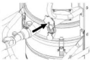
natural_image
Technical line drawing of a mechanical assembly with no visible text or symbolsإغلاق وصلة الش菀
natural_image
Icon showing a gear and wrench inside a square frame (no text or symbols)http://www.kaercher.com/dealersearch