Skyllai - Battery charger VICTRON ENERGY - Free user manual and instructions
Find the device manual for free Skyllai VICTRON ENERGY in PDF.
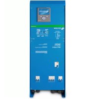
| Product Type | Intelligent Battery Charger |
| Brand | Victron Energy |
| Model | Skylla-i (24/80, 24/100, 1+1 or 3 output versions) |
| Input Voltage | 230 VAC (range 185-265 VAC) |
| Input Frequency | 45-65 Hz |
| Power Factor | 0.98 |
| Charge Voltage (absorption) | 28.8 VDC (adjustable per battery) |
| Charge Voltage (float) | 27.6 VDC |
| Storage Voltage | 26.4 VDC |
| Nominal Charge Current | 80 A or 100 A depending on model |
| Number of Outputs | 2 (1+1) or 3 independent outputs |
| Charge Algorithm | Adaptive 7-step (lead) or 4-step (LiFePO4) |
| Protection | Reverse polarity (fuse), short-circuit, overheating, overvoltage |
| Cooling | Internal fan (temperature controlled) |
| Dimensions (H x W x D) | 405 x 250 x 150 mm |
| Weight | 7 kg |
| Housing Material | Aluminum (blue RAL 5012) |
| Protection Rating | IP 21 |
| Operating Temperature Range | -20 to 60 °C (full power up to 40 °C) |
| Max Humidity | 95% non-condensing |
| Battery Connection | M8 nuts |
| Mains Connection | Clamp screw 10 mm² (AWG 7) |
| Communication Ports | VE.Can (2 x RJ45), NMEA 2000 |
| Parallel Operation | Yes, synchronized via CAN bus |
| Alarm Relay | DPST, 240 VAC/4 A or 35 VDC/4 A |
| Maintenance | Annual connection check; no special maintenance |
| Standards | Safety EN 60335-1/-2-29, emission EN 55014-1, immunity EN 55014-2 |
Frequently Asked Questions - Skyllai VICTRON ENERGY
User questions about Skyllai VICTRON ENERGY
0 question about this device. Answer the ones you know or ask your own.
Ask a new question about this device
Download the instructions for your Battery charger in PDF format for free! Find your manual Skyllai - VICTRON ENERGY and take your electronic device back in hand. On this page are published all the documents necessary for the use of your device. Skyllai by VICTRON ENERGY.
USER MANUAL Skyllai VICTRON ENERGY
1. SAFETY INSTRUCTIONS
1.1. General
- Please read the documentation supplied with this product first, so that you are familiar with the safety signs and directions before using the product.
- This product is designed and tested in accordance with international standards. The equipment should be used for the designated application only.
- WARNING: danger of electric shock
The product is used in combination with a permanent energy source (battery). Even if the equipment is switched off, a dangerous electrical voltage may still be present at the input and/or output terminals. Always disconnect the AC power and the battery before performing maintenance. - The product contains no internal user-serviceable parts. Do not remove the front panel unless the mains and the battery are disconnected. Do not put the product into operation unless all panels are fitted. All maintenance should be performed by qualified personnel.
- Never use the product at sites where gas or dust explosions could occur. Refer to the specifications provided by the manufacturer of the battery to ensure that the battery is suitable for use with this product. The battery manufacturer's safety instructions should always be observed.
- WARNING: do not lift heavy objects unassisted.
1.2. Installation
- Read the installation instructions before commencing installation activities.
- This product is a safety class I device (supplied with a ground terminal for safety purposes). It's AC input and/or output
terminals must be provided with uninterruptible grounding for safety purposes. An additional grounding point is located on the outside of the product. If it can be assumed that the grounding protection is damaged, the product should be taken out of operation and prevented from accidentally being put into operation again; contact qualified maintenance personnel. - Ensure that the connection cables are provided with fuses and circuit breakers. Never replace a protective device by a component of a different type. Refer to the manual for the correct part.
-
Check before switching the device on whether the available voltage source conforms to the configuration settings of the product as described in the manual.
-
Ensure that the equipment is used under the correct operating conditions. Never operate it in a wet or dusty environment.
- Ensure that there is always sufficient free space around the product for ventilation, and that ventilation openings are not blocked.
- Install the product in a heatproof environment. Ensure therefore that there are no chemicals, plastic parts, curtains or other textiles, etc. in the immediate vicinity of the equipment.
1.3. Transport and storage
- During storage or transport of the product, ensure that the mains supply and battery cables are disconnected.
- No liability can be accepted for damage in transit if the equipment is not transported in its original packaging.
- Store the product in a dry environment; the storage temperature should range from -20^ to 60^ .
- Refer to the battery manufacturer's manual for information on transport, storage, charging, recharging and disposal of the battery.
2. INSTALLATION AND WIRING
2.1. Installation
Find a dry and well-ventilated area to mount the Skylla charger and battery. Keep the cable length between the charger and the battery less than 6 meters.
The charger may be wall or floor mounted. Vertical mounting improves the air circulation within the charger cabinet and will prolong the lifetime of the battery charger.
Wall mounting
The unit can best be mounted to a wall using the supplied mounting plate. With this plate fixed to the wall, the charger can be hung on this mounting plate. The charger can then be fixed by installing two screws at the lower backside of the charger. Now the charger is fully secured.
Wiring
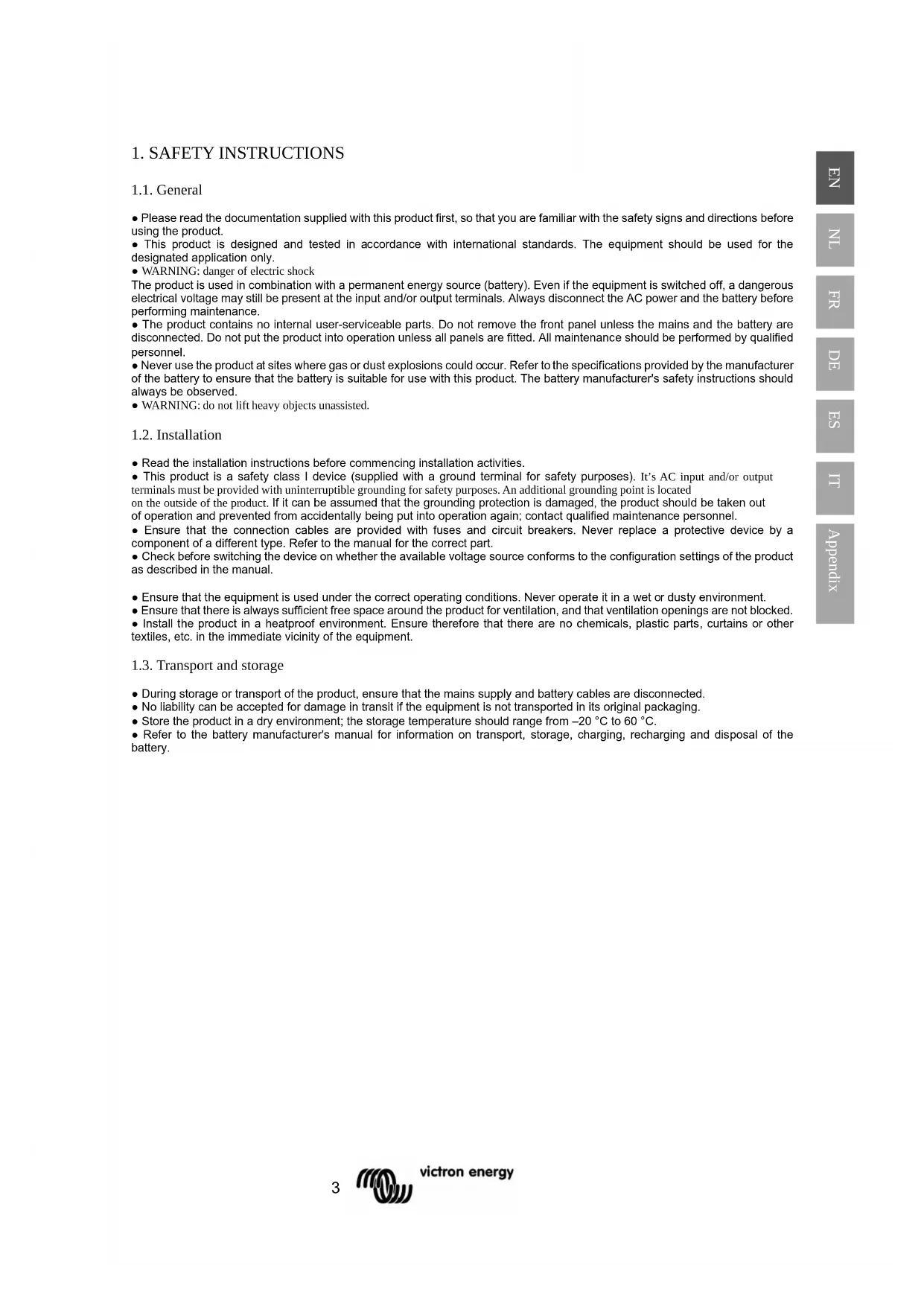
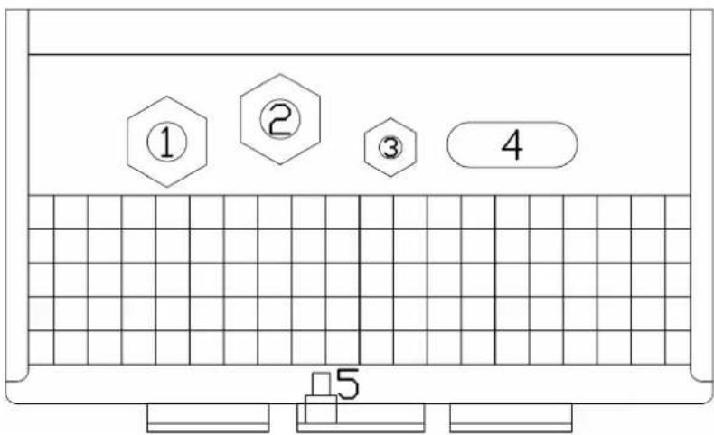
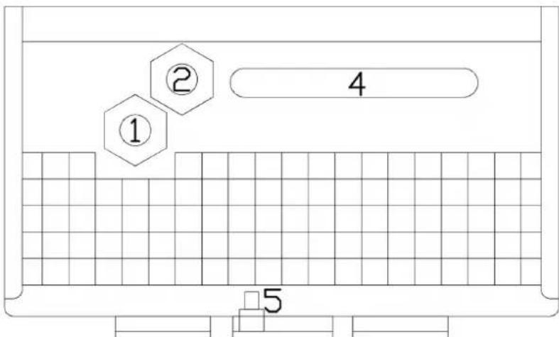
The inlets for the mains cable, the battery cables, the remote functions and the connection to attach the earth cable are located at the bottom of the housing, see Figure 1 for the two output models and figure 2 for the three output models.
Figure 1. Bottom view of cabinet showing cable entries: two output models
- Mains cable
- Remote connections
- Starter battery
- Main battery
- Grounding point
text_image
① ② ③ 4 5Figure 2. Bottom view of cabinet showing cable entries: three output models
- Mains cable
- Remote connections
- (not present)
- Main batteries
- Grounding point
text_image
① ② 4 5Connecting earth
Connect the grounding point (5) to a real earth-point. Connections to earth have to be according to applicable safety standards.
• On a ship: connect (5) to the earth plate or to the hull of the ship.
- On land: connect (5) to the earth of the mains. The connection to the earth of the mains has to be according to applicable safety standards.
• Mobile applications (a vehicle, a car or a caravan): Connect (5) to the frame of the vehicle.
The battery connections of the charger are fully floating with respect to this grounding point.
2.2. Connecting the batteries
Recommended cable cross section:
| Skylla-i type | cable length up to 1,5 m | cable length 1,5 m – 6 m |
| 24/80 (1+1) | 25 mm ^2 35 mm | ^2 |
| 24/80 (3) | 25 mm ^2 to each battery | 35 mm ^2 to each battery |
| 24/100 (1+1) | 35 mm ^2 50 mm | ^2 |
| 24/100 (3) | 35 mm ^2 to each battery | 50 mm ^2 to each battery |
2.2.1. Connecting the starter battery
The starter battery has to be connected using wire of at least 2.5 mm ^2 .
Connect the positive (+) battery-pole to the "Starter battery plus" connector, see figure 2.
2.2.2. Battery connection sequence

The Skylla is NOT protected against reverse battery polarity.
("+" connected to "-" and "-" connected to "+").
Follow the installation procedure. The warranty expires when the Skylla becomes defective due to reverse polarity.

The on/off switch at the front of the cabinet does not switch off the mains supply.

Disconnect the mains supply before making or breaking connections to the battery.
- Disconnect the mains supply.
- Disconnect battery cables from the battery.
- Remove the front cover of the charger.
- Connect battery cables to the charger.
- Connect battery cables to the battery.
2.2.3 Battery disconnection sequence
When disconnecting the battery cables, be very careful not to accidentally short circuit the battery.
- Switch off the charger.
- Disconnect the mains supply.
- Disconnect battery cables from the battery.
- Remove the front cover of the charger.
- Disconnect the negative battery-cable.
- Disconnect the positive battery-cable.
- Disconnect all other cables like temperature sensor and/or voltage sensor used with this particular battery.
text_image
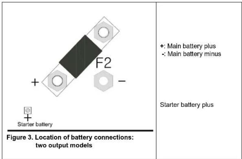
+ F2 - Starter battery Figure 3. Location of battery connections: two output models +: Main battery plus -: Main battery minus Starter battery plusNote:
The starter battery can draw current from the battery connected to the main battery terminals in case the starter battery voltage is lower than the main battery voltage. However, the main battery cannot draw current from the starter battery even when the starter battery is fully charged and the main battery is at minimum charge level.
text_image
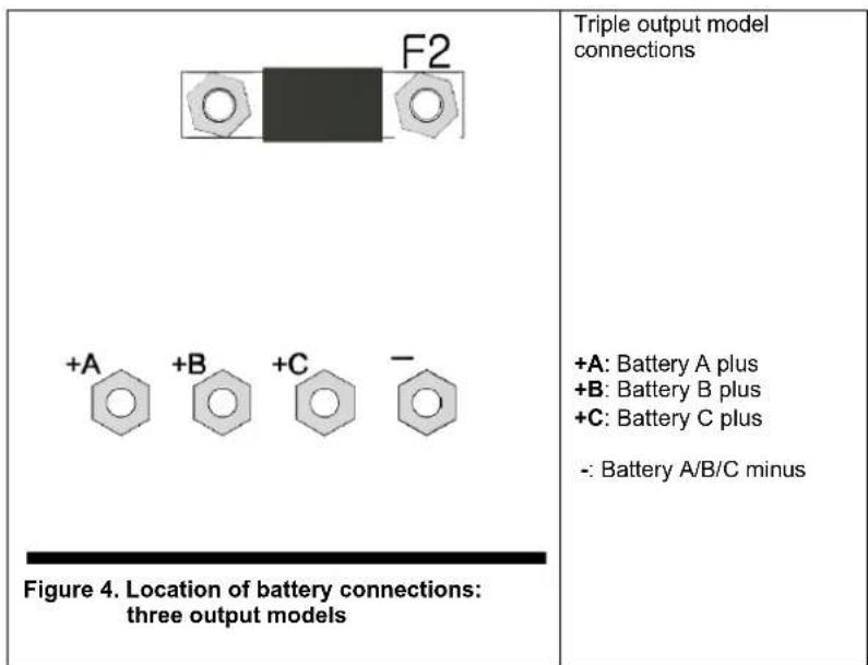
F2 +A +B +C - Figure 4. Location of battery connections: three output models Triple output model connections +A: Battery A plus +B: Battery B plus +C: Battery C plus -: Battery A/B/C minus2.3. Other options
The wiring of these signals must be done with the mains disconnected from the charger.
CONNECTION BLOCK FOR EXTERNAL SENSORS, SWITCH AND RELAY

Figure 5. Connector block
2.3.1. External voltage sensor (see fig 5)
External voltage sensing may be used when accurate battery voltage sensing is important, such as high charging currents in combination with long cables.
To connect the external voltage sensing option, proceed as follows:
- connect a red wire (0.75 mm ^2 ) between the positive battery terminal and connector “+ Voltage sensor”
- connect a black wire (0.75 mm ^2 ) between the negative battery terminal and connector "- Voltage sensor"
- check that the accompanying LED is lit, otherwise check cabling
2.3.2. External temperature sensor (see fig 5)
The external temperature sensor, supplied with the charger, can be connected to these terminals in order to perform temperature compensated charging of the battery. The sensor is electrically isolated and must be connected to the negative pole of the battery.
To connect the temperature sensor, proceed as follows:
- connect the red wire to connector “+ Temperature sensor”
- connect the black wire to connector “- Temperature sensor”
• mount the temperature sensor on the negative pole of the battery - check that the accompanying LED is lit, otherwise check cabling
2.3.3. Remote on/off (see fig 5)
The wiring of the remote switch requires extra attention. Since this input is quite sensitive it is advised to use twisted wires for this connection.
The remote on/off input can also be connected to an open collector optocoupler: the open circuit voltage is 3 V and the closed circuit current is 100 A.
When no remote switch is connected the remote on/off terminals must be short circuited by a short wire.
The remote on/off input can be connected to a Lithium Battery Management System VE.Bus BMS ('charge disconnect' output) with a Skylla-i remote on-off cable ASS030550400.
2.3.4. Alarm relay connections (see fig 5)
The alarm relay is active when the charger is charging normally, no error condition present and the battery voltage is within the voltage range 23.7 V and 33.6 V. The relay is switched off when the charger stops, an error occurs or when the voltage drops below 23.45 V or rises above 33.85 V.
2.3.5. CAN-bus connection (VE.Can)
The VE.Can sockets (RJ45) provide access for monitoring and control. For example with a Skylla-i Control GX panel, a GX device such as the Cerbo GX, or to connect the charger to a NMEA 2000 network.
Several Skylla-i Control GX panels can be connected to one charger or to a set of synchronised and parallel connected chargers. A Lynx Ion can be connected to the Skylla-i charger directly via the VE.CAN-bus, the "allow-to-charge" condition will be communicated via the VE.CAN-bus automatically, no separate wiring is required.
To connect to a NMEA 2000 network, use the VE.Can to NMEA 2000 cable accessory and remove the fuse. Further details are available in our NMEA 2000 and MFD integration guide.
Each end of the VE.Can network should have a bus terminator. This is achieved by inserting a VE.Can terminator in one of the two RJ45 connectors and the network cable in the other. In all intermediate nodes (two VE.Can cables, one in each RJ45 connector), no termination is needed.
The Skylla-i powers the VE.Can network with 12 V DC. Note that its connection is rated for a maximum voltage of 30 V DC: to connect the Skylla-i to a VE.Can network that also contains devices connected to a 48 V battery bank, a special RJ45 cable must be made and used which has pin 2 and pin 6 (NET-S / V+) not connected. This will connect GND, CAN-H and CAN-L, but not the power line.
The two RJ45 sockets in each charger (see figure 7) are parallel connected. There is therefore no functional difference between each of the sockets.
2.3.6. Synchronised parallel operation
Several chargers can be synchronised with the CAN interface. This is achieved by simply interconnecting the chargers with RJ45 UTP cables (bus terminators needed, see section 2.3.5).
The paralleled chargers must have identical DIP switch and rotary switch settings.
A mix of Skylla-i 100 A and 80 A chargers can be paralleled.
Two output and three output chargers cannot be paralleled with each other.
The shore current limit of the parallel charger group can be set with the Skylla-i control panel. The current limit as shown on the panel is the shore current of the group.
The output current of one charger may differ from another charger although connected in parallel.
If one charger from the parallel connected chargers is disconnected, the failure LED will blink on all units that used to operate in parallel mode. To resolve this issue either reconnect the missing charger or power cycle the remaining units.
In case of using remote sensors (voltage and/or temperature), the remote sensor needs to be connected to one of the parallel operating chargers. All other chargers will share the information via the CAN interface. The green LED in the charger with the sensor connected to it, will be lit continuously, the other chargers will blink the corresponding LED.
In case of synchronized parallel operation the LED "ON" will blink every 3 seconds on all paralleled units.
2.3.7 Connecting the AC supply (see fig 6)
- Check if the battery is connected to the charger.
- Remove the front of the battery charger to access the AC input connector.
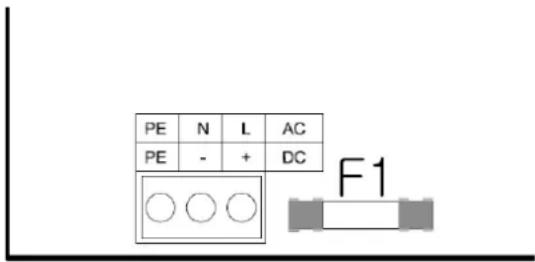
- Connect the mains PE cable (green/yellow) to the AC input connector, terminal PE, located on the circuit board, see Figure
- Connect the mains neutral cable (blue) to the AC input connector terminal N.
- Connect the mains line cable (brown) to the AC input connector terminal L.
- Select the correct battery charge curve before applying AC power (see section 3).
text_image
PE N L AC PE - + DC F1Figure 6. Mains cable connection
3. CONTROL AND ADJUSTMENT
When the charger is installed correctly and before mains power is applied, the charger should be set up to suit the battery connected.
Note about the models with three outputs: all settings are applied to the three outputs simultaneously
text_image
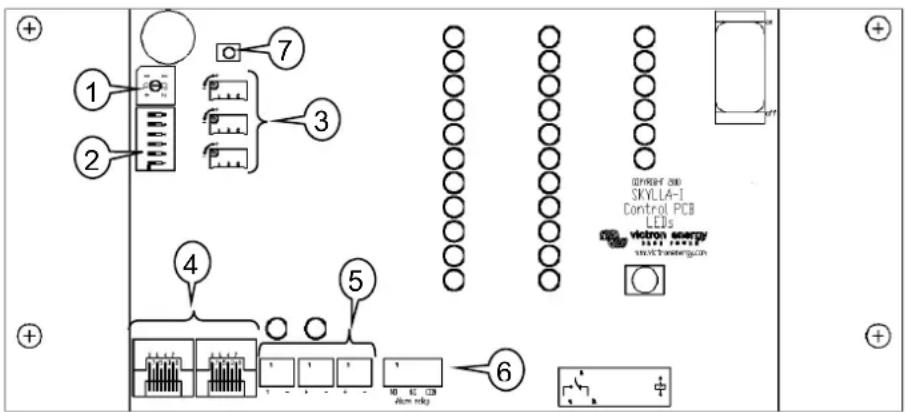
1 2 3 4 5 6 7 8 9 10 11 12 13 14 15 16 17 18 19 20 21 22 23 24 25 26 27 28 29 30 31 32 33 34 35 36 37 38 39 40 41 42 43 44 45 46 47 48 49 50 51 52 53 54 55 56 57 58 59 60 61 62 63 64 65 66 67 68 69 70 71 72 73 74 75 76 77 78 79 80 81 82 83 84 85 86 87 88 89 90 91 92 93 94 95 96 97 98 99 100Figure 7. Internal controls and connections
For this purpose, the control board is fitted with a number of switches and connectors to facilitate the user with the following options:
- Rotary switch for choice of battery type.
- DIP switch for setting various options.
- Fine tuning of current and voltage for position 8 of the rotary switch (and voltage only for position 9)
- CAN-bus connection (RJ45).
- Indicators for correct connection of voltage and temperature sensors.
- Connection block for external sensors, switch and relay.
- Reset settings to factory defaults (press for 5 seconds).
3.1. Rotary switch
The rotary switch provides the user with a selection of preset battery types to be charged. See table below. Warning: the charge voltages as given below are indicative only. Always refer to the battery supplier for the right charge voltages.
| Pos | Description | Absorption | Float | Storage | Equalization | dV/dT |
| V | V | V | maxV@% of Inom | mV/°C | ||
| 0 | Do not use | |||||
| 1 | Gel Victron long life (OPzV)Gel exide A600 (OPzV)Gel MK | 28,2 | 27,6 | 26,4 | 31,8@8 % max 1 hr | -32 |
| 2 | Default settingGel Victron deep discharge, Gel Exide A200AGM Victron deep dischargeStationary tubular plate (OPzS)Rolls Marine (flooded), Rolls Solar (flooded) | 28,8 | 27,6 | 26,4 | 32,4@8 % max 1 hr | -32 |
| 3 | AGM spiral cellRolls AGM | 29,4 | 27,6 | 26,4 | 33,0@8 % max 1 hr | -32 |
| 4 | PzS tubular plate traction batteries or OPzS batteries in cyclic mode 1 | 28,2 | 27,6 | 26,4 | 31,8@25 % max 4 hrs | -32 |
| 5 | PzS tubular plate traction batteries or OPzS batteries in cyclic mode 2 | 28,8 | 27,6 | 26,4 | 32,4@25 % max 4 hrs | -32 |
| 6 | PzS tubular plate traction batteries or OPzS batteries in cyclic mode 3 | 30,0 | 27,6 | 26,4 | 33,6@25 % max 4 hrs | -32 |
| 7 | Lithium Iron Phosphate ( LiFePo_4 ) batteries | 28,4 | n. a. | 26,7 | n. a. | 0 |
| 8 | Adjustable: maximum charge current and absorption and float voltages can be set with potentiometers | Adj. Adj. | 26,4 | (Vabs. + 3,6V)@25 % max 4 hrsVeq-max < 33.6 V | -32 | |
| 9 | Power supply mode | 24,0 | n. a. | n. a. | n. a. | 0 |
3.2. DIP switch
The DIP switches are numbered 6 to 1, top to bottom.
Default settings:
DS-6 Bulk Protection
DS-5 Absorption time
DS-4 Absorption time
DS-3 Adaptive
DS-2 Watch
DS-1 Automatic equalization
| on |
| off |
| on |
| on |
| on |
| off |
3.3. Explanation of settings:
DS-6. Bulk Protection. When switched on, the failure LED will be lit and the charger will shut down when the bulk time exceeds 10 hrs.
DS-5 and DS-4. Absorption time. The combination of switches 5 and 4 sets the maximum absorption time in case of adaptive charging, and a fixed time in case the adaptive mode has been switched off (DS-3).
| DS-5 | DS-4 | Absorption time |
| Off | Off | 2 hrs (preferred for LiFePo_4 batteries) |
| On | Off | 4 hrs. |
| Off | On | 8 hrs. (default) |
| On | On | 12 hrs. |
DS 3. Adaptive. When switched on, the absorption and float time depend on the bulk time (with the maximum time set by DS-5 and DS-4).
The dependencies are as follows:
Absorption time = (bulk time)*20 with a minimum of 30 minutes and a maximum as set by DS-5 and DS-4.
Float time = (bulk time)*20 with a minimum of 4 hrs and a maximum of 8 hrs.
DS-2. Watch. When DS-2 is on, the battery voltage is checked when the charger is switched on. If the voltage exceeds 26V, the charger will consider the battery fully charged, and start in storage mode. If the voltage is lower, the charger will start in bulk mode.
When DS-2 is off, the charger will always start in bulk mode.
DS-1. Automatic equalization. When DS-1 is switched on, the absorption charge will be followed by a voltage limited constant current period (see table). The yellow LED "abs" will blink during equalization.
The current is limited to 8 % of the bulk current for all VRLA (Gel or AGM) batteries and some flooded batteries, and to 25 % of the bulk current for all tubular plate batteries. The bulk current is the rated charger current (80 A or 100 A) unless a lower setting has been chosen (charge current can be reduced with the current setting potentiometer and rotary switch in position 8, or with the CAN-bus interface).
If, as recommended by most battery manufacturers, the bulk charge current is about 20 A per 100 Ah battery capacity (i.e. 500 Ah for a 100 A charger), the 8 % limit translates to 1,6 A per 100 Ah battery capacity, and the 25 % limit translates to 5 A per 100 Ah capacity.
In case of all VRLA batteries and some flooded batteries (rotary switch position 1, 2 or 3) automatic equalization ends when the voltage limit maxV has been reached, or after t = (absorption time)/8, whichever comes first.
For all tubular plate batteries automatic equalization ends after t = (absorption time)/2.
Warning
Some battery manufacturers do recommend a constant current equalization period, and others do not. Do not use constant current equalization unless recommend by the battery supplier.
Rotary switch position 8: manual setting potentiometers
These potentiometers provide adjustable levels for (from top to bottom):
- bulk current (range 0 A .. 100 A for a 100 A charger)
• absorption voltage (range 11.5 V .. 33.5 V) - float voltage (range 11.5 V .. 33.5 V)
Control direction is such that the values increase when turning the potentiometer clockwise. For easy adjustment the charger will automatically jump to the appropriate mode as soon as it detects a change in the position of a potentiometer. When satisfied with the settings, restart the charger and it will go through the regular charge sequence using the new settings.
Software version 2.01 and higher: when adjusting, the current and voltage will be indicated by the LED bars (blinking) on the Skylla-i, and by the display (blinking) on Skylla-i control panel.
Rotary switch position 9: DC power supply mode
The charger can be set to operate as a DC power supply.
In this mode, the charger functions as a constant voltage source with a maximum output current of 80 resp. 100 A. By default the output voltage is set to 24V, if needed the output voltage can be changed by adjusting the absorption voltage potentiometer (range 11.5 V .. 33.5 V). When satisfied with the new setting switch off the charger using the main on/off switch and it will store the voltage level.
When adjusting, the voltage will be indicated by the LED bars (blinking) on the Skylla-i, and by the display (blinking) on Skylla-i control panel.
3.4. Temperature compensation
The temperature sensor should be connected to the minus pole of the battery.
The temperature compensation is set at -32 mV/°C for all 24 V lead acid batteries (see table and fig 7), and all charge states.
The temperature sensor must be installed when:
• ambient temperature of the battery is expected to regularly be lower than 15 °C or to regularly exceed 30 °C
• charge current exceeds 15 A per 100 Ah battery capacity
Temperature compensation is not required for Li-Ion batteries.
3.5. Manual equalize function
With the equalize button on the front, the charger can be put in equalize mode only during absorption and float periods. When the charger is still in bulk mode equalization is not possible.
To enable equalization, press the equalize button for three seconds. The yellow led "abs" and "bulk" will alternate during equalization.
Current and voltage limits are identical to the automatic equalize function (see section 3.3). The equalize duration is however limited to max. 1 hr when triggered with the equalize button.
3.6. Power Control – maximum use of limited shore current
A maximum input current can be set in order to avoid fusing the mains supply.
This adjustment is only available with the optional Skylla-i control panel or the Color Control GX panel.
4. OPERATION
4.1. Battery charging
After applying mains power and switching the unit ON:
• all LEDs will be lit during two seconds
• the green LED will then be on to indicate the unit is "On"
• the state of charge will be indicated by lighting one of four yellow LEDs
• the actual output voltage and current will be indicated by the appropriate red LED bars
• the internal fans may run depending upon the temperature inside the cabinet (temperature controlled)
In case the red LED is lit, refer to section 6.
4.2. Seven stage charge curve for lead-acid batteries
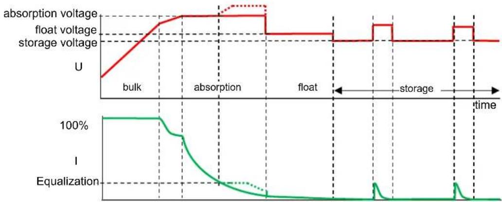
line
| Time Segment | absorption voltage | float voltage | storage voltage | | ------------ | ------------------ | ------------- | --------------- | | bulk | U | U | U | | absorption | U | U | U | | float | U | U | U | | storage | U | U | U | | time | U | U | U |Figure 8.
4.2.1. Bulk
Entered when the charger is started (DS-2 on and battery voltage <26 V, or DS-2 off), or when the battery voltage falls below 26.4 V (due to a heavy load) during at least 1 minute. Constant current is applied until gassing voltage is reached (28.8 V for a 24 V battery).
4.2.2. BatterySafe
If absorption voltage is set higher than 28.8 V, the rate of voltage increase beyond 28.8 V is limited to 14 mV/minute, in order to prevent excessive gassing.
4.2.3. Absorption
After the absorption voltage has been reached, the charger operates in constant voltage mode.
In case of adaptive charging, the absorption time is dependent on the bulk time, see section 3.3.
4.2.4. Automatic equalization
If automatic equalization has been set to "on", the absorption period is followed by a second voltage limited constant current period: see section 3.3. This feature will charge VRLA batteries to the full 100% , and prevent stratification of the electrolyte in flooded batteries.
Alternatively, manual equalization can be applied.
4.2.5. Float
Float voltage is applied to keep the battery fully charged.
In case of adaptive charging, the float voltage time is dependent on the bulk time, see section 3.3.
4.2.6. Storage
After float charge the output voltage is reduced to storage level. This level is not sufficient to compensate for slow self-discharge of the battery, but will limit water loss and corrosion of the positive plates to a minimum when the battery is not used.
4.2.7. Weekly battery "refresh"
Once a week the charger will enter Repeated Absorption-mode during one hour to 'refresh' (i. e. to fully charge) the battery.
4.3. Four stage charge curve for Lithium-Iron-Phosphate (LiFePo4) batteries
4.3.1. Bulk
Entered when the charger is started (DS-2 on and battery voltage <26 V, or DS-2 off), or when the battery voltage falls below 26.7 V (due to a heavy load) during at least 1 minute. Constant current is applied until absorption voltage is reached (28.4 V for a 24 V battery).
4.3.2. Absorption
After the absorption voltage has been reached, the charger operates in constant voltage mode.
The recommended absorption time is 2 hours.
4.3.3. Storage
After absorption charge the output voltage is reduced to storage level. This level is not sufficient to compensate for slow self-discharge of the battery but will maximize service life.
4.3.4. Weekly battery "refresh"
Once a week the charger will enter Repeated Absorption-mode during one hour to "refresh" (i. e. to fully charge) the battery.
5. MAINTENANCE
This charger does not require any specific maintenance. However, an annual check of the battery connections is recommended. Keep the charger dry, clean and free of dust.
6. TEMPERATURE COMPENSATION
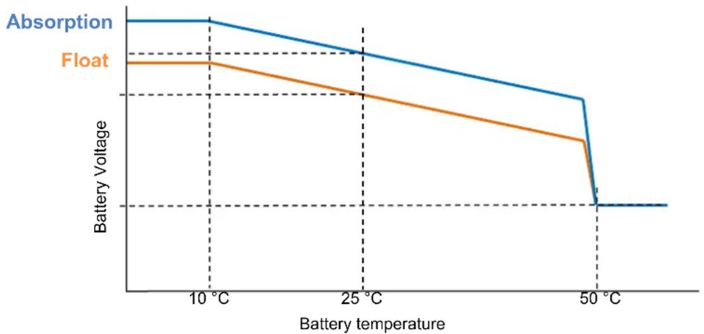
line
| Battery temperature | Absorption | Float | | ------------------- | ---------- | ----- | | 10 °C | High | High | | 25 °C | Medium | Low | | 50 °C | Low | Low |Figure 9.
7. TROUBLESHOOTING
General problems:
| Problem | Possible cause | Solution |
| Charger does not function | The mains is not ok | Measure mains: 180 -265 VAC |
| Input or output fuses are defective | Return product to your dealer | |
| The battery is not fully charged | A bad battery connection | Check battery connection |
| The battery select switch is in the wrong position | Select correct battery type with rotary switch | |
| Cable losses too high | Use cables with larger cross section. Use external voltage sensing | |
| The battery is being overcharged | The battery select switch setting is switch is in the wrong position | Select correct battery type with rotary switch |
| A battery cell is defective | Replace battery | |
| Battery temperature too high | Overcharging or fast charging | Connect external temperature sensor |
| Failure led on (see also chapter 9) | Battery voltage too high (>36 V) | Check all charging equipment Check cables and connections |
| Bulk time too long (>10 hrs) | Possible cell failure, or higher charge current needed | |
| Temperature in cabinet too high | Check air vents of cabinet Improve cooling of environment | |
| Failure led blinks | CAN-bus connection lost | Reconnect CAN-bus or switch the charger off and back on if the CAN-bus connection is no longer required |
List of error codes as shown on remote control panels such as the Skylla-i Control and the Color Control:
| Error code | Possible cause | Solution |
| Error 1: battery temperature too high | Overcharging or fast charging | Connect external temperature sensor |
| Error 2: battery voltage too high | Wiring mistake, or another charger is over charging | Check all charging equipment Check cables and connections |
| Error 3, 4 and 5: temp. sense error | Wiring mistake or temperature sensor broken | Check the temperature sensor wiring and if that doesn't help replace the temperature sensor |
| Error 6, 7, 8 and 9: voltage sense error | Wiring mistake | Check the voltage sensor wiring |
| Error 17: charger temperature too high | The heat generated by the charger cannot be removed | Check air vents of cabinet Improve cooling of environment |
| Error 18 | Internal error | Contact Victron service |
| Error 20: charger bulk time expired | After 10 hours of bulk charging, the battery voltage has still not reached the absorption voltage | Possible cell failure, or higher charge current needed |
| Error 34: Internal error | Contact Victron service | |
| Error 37: No input voltage (only for the three output version) | Mains removed or AC-input fuse blown | Check main availability and fuse |
| Error 65: charger disappeared during operation | One of the other chargers with which this charger was synchronizing has disappeared during operation | To clear the error, switch the charger off and back on |
| Error 66: Incompatible device | The charger is being paralleled to another charger that has different settings and/or a different charge algorithm | Make sure all settings are the same and update firmware on all chargers to the latest version |
| Error 67: BMS connection lost Connection to the BMS lost. | Check the CAN-bus cabling. When the charger needs to operate in stand-alone mode again, press the internal “reset settings to factory defaults” button for 5 seconds. | |
| Error 113, 114 | Internal error | Contact Victron service |
| Error 115 | Communication error | Check wiring and terminators |
| Error 116, 117 | Internal error | Contact Victron service |
- SPECIFICATION
| Skylia-i | 24/80 (1+1) | 24/80 (3) | 24/100 (1+1) | 24/100 (3) |
| Input voltage (VAC) 230 V | ||||
| Input voltage range (VAC) | 185-265 V | |||
| Input voltage range (VDC) | 180-350 V | |||
| Maximum AC input current @ 180 VAC | 16 A | 20 A | ||
| Frequency (Hz) | 45-65 Hz | |||
| Power factor 0,98 | ||||
| Charge voltage 'absorption' (VDC) (1) | 28,8 V | |||
| Charge voltage 'float' (VDC) | 27,6 V | |||
| Charge voltage 'storage' (VDC) | 26,4 V | |||
| Charge current (A) (2) | 80 A | 3 x 80 A(max total output: 80 A) | 100 A | 3 x 100 A(max total output: 100 A) |
| Charge current starter batt. (A) | 4 A | n. a. | 4 A | n. a. |
| Charge algorithm | 7 stage adaptive | |||
| Battery capacity (Ah) | 400-800 Ah | 500-1000 Ah | ||
| Charge curve, Li-Ion | 4 stage, with on-off control or CAN-bus control | |||
| Temperature sensor | Yes | |||
| Can be used as power supply Yes | ||||
| Remote on-off port | Yes (can be connected to a Li-Ion BMS) | |||
| VE.Can communication port | Two RJ45 connectors, NMEA 2000 protocol, galvanically isolated.Integrated 12 V CAN-bus power supply, 30 VDC maximum ^19 | |||
| Synchronised parallel operation | Yes, with the CAN-bus | |||
| Remote alarm relay | DPST AC rating: 240 VAC/4 A DC rating: 4 A up to 35 VDC, 1 A up to 60 VDC | |||
| Forced cooling | Yes | |||
| Protection | Battery reverse polarity (fuse) Output short circuit Over temperature | |||
| Operating temp. range | -20 to 60 °C (Full output current up to 40 °C) | |||
| Humidity (non-condensing) | max 95 % | |||
| ENCLOSURE | ||||
| Material & Colour aluminium (blue RAL 5012) | ||||
| Battery-connection | M8 bolts | |||
| 230 VAC-connection | screw-clamp 10 mm ^2 (AWG 7) | |||
| Protection category IP 21 | ||||
| Weight kg (lbs) | 7 (16) | |||
| Dimensions hxwxd in mm(hxwxd in inches) | 405 x 250 x 150(16.0 x 9.9 x 5.9) | |||
| STANDARDS | ||||
| Safety | EN 60335-1, EN 60335-2-29 | |||
| Emission | EN 55014-1, EN 61000-6-3, EN 61000-3-2 | |||
| Immunity | EN 55014-2, EN 61000-6-1, EN 61000-6-2, EN 61000-3-3 | |||
| 1) Output voltage range 20-36 V.Can be set with rotary switch or potentiometers. | 2) Up to 40 °C (100 °F) ambient.Output will reduce to 80 % at 50 °C, and to 60 % at 60 °C.3) When connecting the Skylla-i in a VE.Can network that also contains devices connected to a 48 V battery bank, make sure to use a special RJ-45 cable, which has pins 2 and 6 (NET-S / V+) not connected. | |||
9. LED INDICATION
LED indication:
on
blinking
○ off
LEDs: on (O), bulk (B), absorption (A), float (F), storage (S), failure (E)
| Skylla-i | Panel | |||||||||||
| LEDs O B A F S E | B A | F E | ||||||||||
| Bulk | ● | ● | ○ | ○ | ○ | ○ | ● | ○ | ○ | ○ | ||
| BatterySafe (dU/dt) | ● | ● | ● | ○ | ○ | ○ | ● | ● | ○ | ○ | ||
| Absorption | ● | ○ | ● | ○ | ○ | ○ | ○ | ● | ○ | ○ | ||
| Automatic equalization (DS-1 on) | ● | ○ | ● | ● | ○ | ○ | ○ | ● | ● | ○ | ||
| Float | ● | ○ | ○ | ● | ○ | ○ | ○ | ○ | ● | ○ | ||
| Storage | ● | ○ | ○ | ○ | ● | ○ | ○ | ○ | ◎ | ○ | ||
| Repeated absorption | ● | ○ | ● | ○ | ● | ○ | ○ | ● | ◎ | ○ | ||
| Manual equalization (*1) | ● | ◎ | ◎ | ○ | ○ | ○ | ◎ | ◎ | ○ | ○ | ||
| Power supply mode | ● | ● | ● | ● | ● | ○ | ● | ● | ● | ○ | ||
(\*1) Blink alternating
Fault situations
| LEDs | O | B | A | F | S | E | ||||
| Battery temperature sensor | ● | ○ | ◎ | ◎ | ○ | ● | ||||
| Battery sense wires | ● | ◎ | ◎ | ○ | ○ | ● | ||||
| Bulk time protection (10 hrs) | ● | ◎ | ○ | ○ | ○ | ● | ||||
| Charger temperature too high | ● | ◎ | ◎ | ◎ | ◎ | ● | ||||
| Charger over-current | ● | ◎ | ○ | ○ | ◎ | ● | ||||
| Charger over-voltage | ● | ○ | ◎ | ○ | ◎ | ● | ||||
| BMS connection lost | ● | ○ | ○ | ◎ | ◎ | ● | ||||
| Internal error | ● | ◎ | ◎ | ◎ | ○ | ●(e.g. calibration data lost) |
Note: LEDs blink synchronously
The panel lights the error led and displays the error code.
1. VEILIGHEIDSVOORSCHRIFTEN
1.1. Algemeen
text_image
① ② ③ 4 5text_image
① ② ③ ④ ⑤ ⑥ ⑦ ⑧ ⑨ ⑩ ⑪ ⑫ ⑬ ⑭ ⑮ ⑯ ⑰ ⑱ ⑲ ⑳ ⑴ ⑵ ⑶ © NORTH 2014 SKYLLA-I Control PCB LEDs Victor's energy and the energy7. PROBLEEMOPLOSSING
Algemene problemen:
LEDs: on (O), bulk (B), absorption (A), float (F), storage (S), failure (E)
text_image
① ② ③ 4 5text_image
+ F2 - Starter batterychemical
Chemical structure diagram showing a hexagonal ring system with labeled positions +A, +B, +C, and -LED : On (O), Bulk (B), Absorption (A), Float (F), Stockage (S), Erreur (E)
text_image
① ② ③ 4 5When adjusting, the voltage will be indicated by the LED bars (blinking) on the Skylla-i, and by the display (blinking) on Skylla-i control panel.
text_image
① ② ③ 4 5text_image
① ② ③ 4 5natural_image
Three circular patterned circles with diagonal hatching, no text or symbols presenton
© lampeggiante
○ off
LED: ON (O), bulk (B), mantenimento (F), stoccaggio (S), guasto (E)
| Skylla-l | Pannello | |||||||||||
| LED O B A F S E | B A | F E | ||||||||||
| Prima fase | ● | ● | ○ | ○ | ○ | ○ | ● | ○ | ○ | ○ | ||
| BatterySafe (dU/dt) | ● | ● | ● | ○ | ○ | ○ | ● | ● | ○ | ○ | ||
| Assorbimento | ● | ○ | ● | ○ | ○ | ○ | ○ | ● | ○ | ○ | ||
| Equalizzazione automatica (DS-1 on) | ● | ○ | ● | ● | ○ | ○ | ○ | ● | ● | ○ | ||
| Mantenimento | ● | ○ | ○ | ● | ○ | ○ | ○ | ○ | ● | ○ | ||
| Stoccaggio | ● | ○ | ○ | ○ | ● | ○ | ○ | ○ | ◎ | ○ | ||
| Assorbimento ripetuto | ● | ○ | ● | ○ | ● | ○ | ○ | ● | ◎ | ○ | ||
| Equalizzazione manuale (*1) | ● | ◎ | ◎ | ○ | ○ | ○ | ◎ | ◎ | ○ | ○ | ||
| Modalità alimentazione | ● | ● | ● | ● | ● | ○ | ● | ● | ● | ○ | ||
Appendix A: Dimensions
natural_image
Simple line drawing of a container with six circular holes and a grid pattern at the bottom (no text or symbols)Appendix B: Wall mounting bracket
Bijlage B: Wandmontagebeugel
PO Box 50016 | 1305 AA Almere | The Netherlands
E-mail : sales@victronenergy.com
www.victronenergy.com